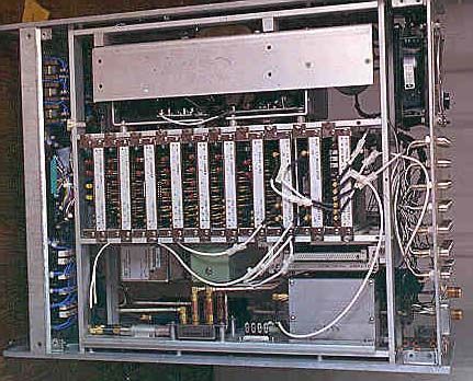
Top View
On the left is the front panel and the rear panel is on the right.
Power Supplies at the Top.
The big power supplyat the top is +5 Volts.
Under it can be seen the two smaller 12 Volt supplies.
Card Cage in the Center
In the center are the plug in cards A-1 through A-10.
There is a spare space for another card on the right.
Just below the card cage on the right is the extender card.
The RF deck is shown below the card cage.
The HP 10.23 MHz oscillator is the chrome unit in the upper left of the
RF area.
Just to the right of the HP is the Greenray Ind. 81.84 MHz oscillator.
The large box in the lower right is one of the two California Microwave
PLL sources.
The other Calif. Micro. source is below the visable one.
One of the W-J mixers can be seen at the bottom center.
The 2 red cylinders seen comming up from the mixer are 3 dB pads.
The left port of the mixer is routed through 0.141" coax to the Acronetics
combining dual filter.
The A-9 L1 Modulator card output J5 has an SSMB coax routed to the
6 dB pad on the left end of the same filter.
The right side of the filter is routed via 0.141" coax to the
top of the 3 dB pad that feeds the center I port of the mixer.
Back to 5001 , Main, Navigation web pages