This frame panel assembly is used on the PRC-126, PRC-128 and PRC-136 radios. By showing the label as a separate line item the frame panel assembly part number does not change for the three different receiver-transmitters. It is also very similar to the frame panel assembly used on the PRC-68B and less so the PRC-68A.
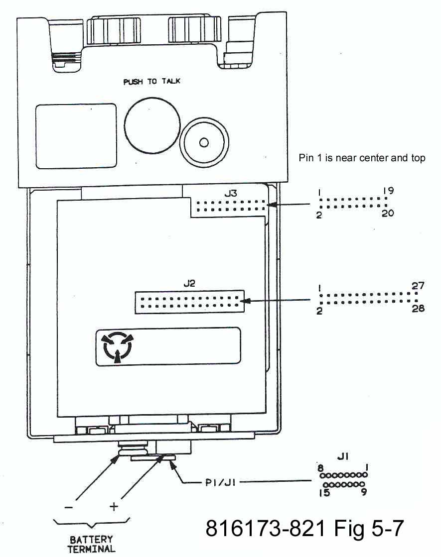
Remove both modules and test just the frame/panel assembly. It's handy to have a micro test clip on one or both test prods to grab onto the pins on J2 and J3.See Figure 5-7 for component location and pin numbering. Note that J2 and J3 show op on both sides of the frame panel back bone, but with different pins sticking up. Pin 1 on these connectors is near the center top when looking at either side. All the odd numbered pins are on the top row and even numbers on the bottom row. Since you are seeing the same connector on both sides the right to left order reverses depending on which side you are looking at.
See the 816173-821 Frame/Panel Schematic (1/2 MB A size pdf) to clarify what's being tested. This has BOLD lines for ground, gray for TTL logic and some colors used to make understanding somewhat easier.
A Fluke model 87 was used for the following measurements. It uses 1.0 mA in the diode mode. Using resistance to check diodes gives different results on different meters because of different test currents. The 1 mA forward voltage drop also is a very good indicator of the diode type.
Item Position Mode From/Blk To/Red Indication Comment 1 DC Power VOL/OFF On Diode J2-12 Batt + 0.20 Volts CR1 fwd & S2 on 2 VOL/OFF Off " J2-12 Batt + OL (Over Load = open) S2 off 3 VOL/OFF On " J2-12 AUDIO-E 0.20 CR2 fwd & S2 on 4 " Gnd
J2-11
chassis frame
control panelBatt - 0.00 5 SVM Jmp Plug Plug Installed Ohms J2-18 J2-20 < 1 Ohms Tx Jmp 6 Plug Installed " J2-5 J2-28 < 1 Rx Jmp 7 J1-1 J2-18 < 1 8 J1-2, 10, 13 Gnd < 1 9 J1-3 J2-4 < 1 10 J1-4 J2-28 < 1 11 J1-5 J2-5 < 1 12 J1-6 J2-7 < 1 13 J1-7 J2-23 < 1 14 J1-8 J2-3 < 1 15 J1-9 J2-20 < 1 16 J1-11 J2-12 < 1 17 J1-12 J2-10 < 1 18 J1-14 J2-22 < 1 19 J1-15 Batt + < 1 20 SPKR/MIC Ohms Gnd J2-25 17 - 27 21 Diode Gnd J2-25 0.02 hear weak click 22 Controls SQ DSBL Press Ohms Gnd J2-23 < 1 23 INCR Press " Gnd J2-1 < 1 24 SET Press " Gnd J2-2 < 1 25 PUSH
TO
TALKPress " Gnd J2-27 < 1 26 ANT A " J3-17 J3-11 1.2 k - 1.8 k Logic 27 B " " J3-9 1.2 k - 1.8 k " 28 C " " J3-7 1.2 k - 1.8 k " 29 D " " J3-5 1.2 k - 1.8 k " 30 E " " J3-3 1.2 k - 1.8 k " 31 50 " " J3-13 1.2 k - 1.8 k " 32 ANT J3-16 8 K - 12 k " 33 A Cap " J3-11 5 nF RF 34 B " " J3-9 " " 35 C " " J3-7 " " 36 D " " J3-5 " " 37 E " " J3-3 " " 38 50 " " J3-13 " " 39 " " Gnd 0.01 uF " 40 CHAN 1 Ohms J3-8 J3-11 < 1 Logic 41 2 " " J3-9 < 1 " 42 3 " " J3-7 < 1 " 43 4 " " J3-3 < 1 " 44 5 " " J3-5 < 1 " 45 6 " J3-4 J3-5 < 1 " 46 7 " " J3-3 < 1 " 47 8 " " J3-7 < 1 " 48 9 " " J3-9 < 1 " 49 10 " " J3-11 < 1 " 50 VOL " Gnd J2-26 70 k - 130 k audio 51 OFF " " J2-24 < 100 " 52 Full CW " J2-26 " < 20 k " 52 Display LCD Diode Gnd J3-15 1.80 Back Light 54 " J3-12 Gnd 0.56 +5 pwr 55 Ohms J3-6 Gnd open data 56 " J3-10 Gnd open clock 57 Connector AUDIO Ohms pin A Gnd < 1 Gnd 58 " pin B J2-17 < 1 ext spkr 59 " pin C J2-19 < 1 PTT 60 " pin D J2-21 < 1 MIC 61 VOL/OFF On Diode J2-12 pin E 0.20 Volts CR2 fwd & S2 on 62 " pin F J3-14 < 1 Ext Data
Back to Brooke's PRC-68 Radio Family, Squad Radio, Military Information, Electronics, Home, Squad Radio Family Battery Portrait, Squad Radio DC Power Sources, page
[an error occurred while processing this directive] page created 6 July 2001.