C-11166/GRC-206 Universal Radio System Control URSC
© Brooke Clarke 2008
Background
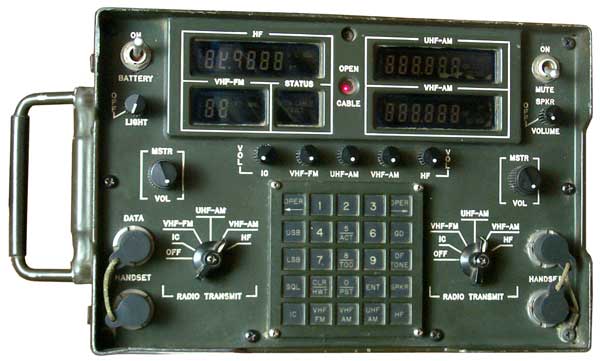
This is the control box for the GRC-206
system. It's designed so that it can be placed between two
operators and they each can control some part of the system.
It connects to the system by either fiber optic cable or a wired
connection. The GRC-206 system supports two of these
controllers (up to four operators, all at one time?).
When used remote from the system it's powered from a couple of
BA-5590 batteries (my 5590BAv2 battery
adapter works). Don't yet understand why there's two
batteries.
Numbers
NSN:
5820-01-411-2903
p/n: 724760-801
p/n: 812085-801
NSN: 5820-01-141-4878
FO4606-81-C-0017contract:
Connectors, Controls and Displays
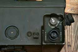
Right Side
The Fiber Optic connector for a two
core cable (probably one for Tx and one for Rx). Also J6 a 5
male pin circular connector marked PWR which can be used to power
the control when it's mounted in a vehicle to save the
batteries. Also J6 probably supports a wire line interface
in lieu of the fiber optic interface. That would allow
removing the FO cable when the control is mounted in the
vehicle. Note that J6 would mate directly to either J8 or J9
on the
Signal
Distribution Unit reinforcing the idea that you can use
either a wired or FO interface.
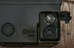
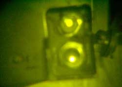
In the photos below of the Fiber Optic connector the fiber at the
bottom (the taller one) is the transmit fiber. The
fiber light source is IR so is not visible to the naked eye.
I was hoping that the digital camera's IR response would be enough
to see the IR but it's a subtle difference between on and off.
|
|
|
Visible
Light C-11166 Off
|
Visible
Light C-11166 On |
IR (PAS-6) C-11166 On |
Front Panel
Left to right, top to bottom:
Battery off - ON switch
Four Displays, one each for HF, UHF-AM, VHF-FM, STATUS, VHF-AM and
in the center a Red Lamp OPEN CABLE.
MUTE - ON switch
OFF-LIGHT knob
SPKR OFF-VOLUME knob
Volume knobs for: IC, VHF-FM, UHF-AM, VHF-AM, HF
Left Operator's Controls
MSTR-VOL knob
Data U-229 type connector
HANDSET U-299 type connector
radio select switch: OFF, IC, VHF-FM, UHF-AM, VHF-AM, HF
Right Operator's Controls
MSTR-VOL knob
2 each HANDSET U-299 type connectors (maybe only the left operator
can use data communications?)
radio select switch: OFF, IC, VHF-FM, UHF-AM, VHF-AM, HF
Common Keypad
This is a 5x5 keypad with markings as shown below that's shared by
the two operators.
<- OPER
|
1
|
2
|
3
|
OPER->
|
USB
|
4
|
5
ACT
|
6
|
GD
|
LSB
|
7
|
8
TOD
|
9
|
DF
TONE
|
SQL
|
CLR
HWT
|
0
PST
|
ENT
|
SPKR
|
IC
|
VHF
FM
|
VHF
AM
|
UHF
AM
|
HF
|
Left Side
Fold up carrying handle.
Top
Speaker
Bottom
Battery compartment for two each BA-5590 (or equivalent)
batteries. It's difficult to remove a battery. So it's
good to put some cord or belt around the battery BEFORE installing
it into the box. I used a length of dental floss and doubled
it. We'll see when I try to get that 5590BA out.
I'm using one of the 5590BAv2 battery adapters to power the
C-11166. The dental floss is there to help get the battery
out since there's not much exposed to get a good purchase on the
battery.
It's not clear why two batteries are being used.
Operation
When a single 5590BA battery adapter
is installed and the BATTERY switch is turned ON there are some
sounds and the STATUS display window shows OPEN CABLE FAULT
and the red OPEN CABLE lamp is one. Noise background and a
constant tone.
The other displays are not showing any data. but the segments can
be seen:
HF: "call", dd.dddd, U, L, SQL, PT
UHF-AM: "call", ddd.ddd PT GD SQL
VHF-FM: :call" dd PT MNL
VHF-FM: "call" ddd.ddd PT DF GD SQL
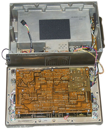
Inside
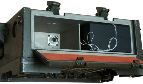
 Battery Box
Shown at the top of the photo is the battery box. It
contains the two BA-5590 batteries and in the lower left the fiber
optic interface in subassembly A1J1 with it's owncqble and
2x5 header. J6 the wireed power and control connector has
Red, Black, Violet and Orange wires plus a black chassis ground
wire going across to the other side of the box. The Red and
violet wires go to P2 mating with the front panel. The black
and orange wires go to a 2x13 headet connected to p/n
812666-801subassembly whose function may be related to power
conditioning. J1 on this assembly goes to the fornt
panel. A guess would be the three cables are for: fiber
optic data, wire line data and DC power.
J6 PWR is a MS 3114E-10-6P this is a six pin connector wired:
Pin
|
Wire
|
Destination
|
Function
|
A
|
nc
|
|
|
B
|
big
black
|
P2x13-opposite 7
|
gnd
|
C
|
violet
|
P2-7
|
|
D
|
orange
|
P3-opposite 3
|
|
E
|
red
|
P2x13-1
|
|
F
|
small
black
|
E9 chassis ground
|
gnd
|
C11166A
This is for the GRC-206(V)3 that
uses the RT-1523
SINCGARS VHF FM
ratios instead of the Vietnam era
RT-246.
Related
The two web pages that have information on the GRC-206 are: PRC-104 and MT-6250.
GRC-2006 is a very similar dual remote
control probably for the same FAC function, but a different
compliment of radios.
Back to Brooke's Products for Sale,
Military Information, PRC-68 Family of Squad Radios, U229 Audio Accessories, Audio Connectors, Electronics, Personal
Home, PRC68.com page
[an error occurred while processing this directive] page created 10 Dec
2008.
