Datron World Communications Inc.
MT1060DS
This is a Docking Station for the Datron PRC1060/70/80 Squad Radios.
This series is very similar to the PRC68/126 series of radios so
should
work with them if some modifications
are made.
These might be done so that the operation of the MT1060DS would be
the same with a Datron radio and still work witht the PRC-68 seires
radios.
When using a Squad Radio in a vehicle, the use of a microphone,
like
the M-80, is much more convenient than using the handset (H-250)
or trying
to speak into the radio microphone and operate the radio PTT
switch.
Since it would be good to power the radio from the vehicle 13.6
Volt supply
something needs to be added between the radio and the mic.
It may
be that the LS-454 would allow power to be routed to the radio,
the M-80
mic connected and a better quality speaker would be used.
Powered unit with +12.0 Volts from anode of big diode and
connected
a handset.
Current draw is 80 ma in Rx mode and 110 ma in Tx mode with no
speaker
or radio attached.
Got a MT1060DS-MS manual from Mike
Murphy.
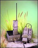
In this photo you can see the power amplifier on the left under a
squad
radio. On the right is the MT1060DS with a squad radio
installed.
A PRC-68 or PRC-126 will not fit into the slot because they are
wider where
the battery fasteners are located. Note that the top of the
radio
points to the back and for a PRC-68 series radio you can not
easily change
the volume or channel controls. Even for the 1060 series
radio it
looks like it would be difficult.
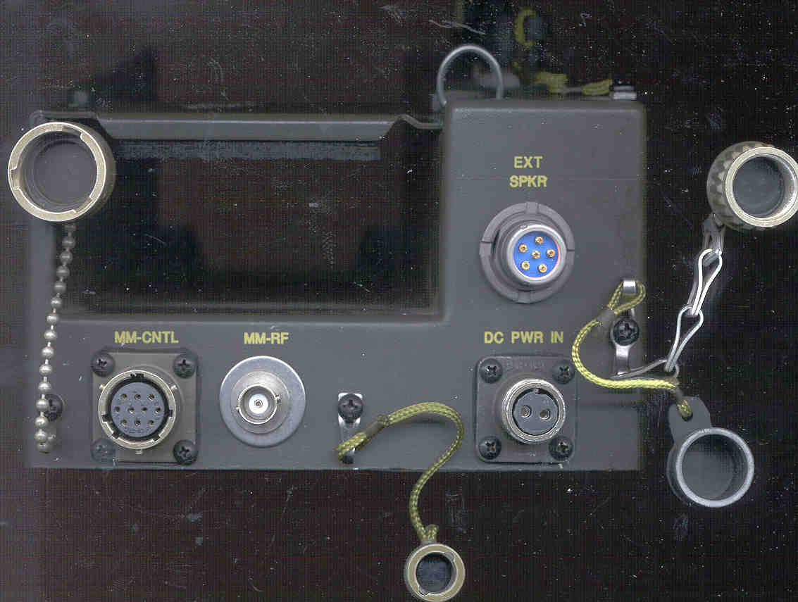
Front Panel
J4 MM-CNTL
Bendix 9507 PT02E-12-10S (does mate with Newark 93F3378)
The Newark p/n 93F3378 includes the ITTC MS3116F12-10P
connector
and the Cannon p/n 057-3007-000 end bell assembly
interface connection to MT1060MM 35 Watt RF Power Amplifier
A - J4#1 - Ground
B - J4#2
C - J4#3 - 8.2 VDC Rx, 0 VDC Tx (handset PTT depressed, you can
hear
T/R relay in MT1060MM)
D - J4#4
E - J4#5
F - J4#6
G - J4 no contact
H - J4#8 - 11.75 Volts when PWR ON
J - J4#9 - 4 Ohms to ground
K - J4#10
J11 - MM-RF
to vehicle ANT
This is a DC open connection. E2 on PCB
J5 - DC PWR IN
Crown 3102A10SL (does mate with Newark 50F2540
(includes
both MS3106F10SL-4P & MS3106E-10SL clamp))
A- hot Positive DC input (voltage range 10 to 16 VDC) - J5#2
B - Ground - J5#1
J7 - U-182 - EXT SPKR
An LS-454 or equivalent should work here.
A - Gnd - J7#1 - ground
B - J7#2 = J7#3 -\
---
Speaker hot
C - J7#3 = J7#2 -/
D - n.c.
E - n.c.
F - n.c.
Top Panel -
J3 - U-182 - HANDSET
Uses standard U-229 type handsets like the H-251.
A - J3#1 - ground
B - J3#2 - ear piece
C - J3#3 - PTT
D - J3 - Mic
E - n.c.
F - n.c.
J3#5 - gnd
J3#6 & 7 - n.c.
PWR OFF - PWR ON - SPKR ON
J6#1 & 2 - short for SPKR ON
J6#3 & 4 - short for PWR ON
AMP OFF - AMP ON
J9 - open for AMP ON
VOLUME
J8 - 10 k Ohm pot, wiper on center
Back Panel -
J2 - Squad Radio Interface
Bendix 9507 PT02E-12-10S (does mate with Newark
93F3378)
The Newark p/n 93F3378 includes the ITTC MS3116F12-10P
connector
and the Cannon p/n 057-3007-000 end bell assembly
A - J2#1 = gnd [wire to U-183 A - gnd]
B - J2#2 = EAR - 1 k Ohm to gnd to turn off the radio internal
speaker
[wire to U-183 B-ear]
C - J2#3 = PTT +8.2 VDC Rx, 0 VDC Tx [wire to U-183 C with
a 5 V Zener diode cathode on line, anode to ground]
D - J2#4 = MIC +3.8 VDC [wire to U-183 D-mic]
E - J2#5 = Gnd for Mice [N.C. U-183]
F - J2#6 = digital from PRC1060, -0.2 VDC [N.C. U-183]
G - J2#7 = digital to PRC1060, +0.2 VDC [N.C. U-183]
H - n.c.\
J - n.c. |- [inside MT1060DS
add
a wire from (L1 C2 end) to pick up +13.6 VDC to one
of these cable to U-183 E-Ext Pwr &]
K - n.c./
[N.C.
to U-183 F-Fill]
J1 - BNC(f)
E1 on PCB
to Squad Radio ANT connector stock version has +8.4 VDC to
power
Datron PRC1060/70/80 Squad Radios.
In the coax cable between the MT1060DS and
the
Squad radio there needs to be a series .01 uF cap and 1.8 K
Ohm to ground
on the squad radio side of the cap. This needs
to be done maintaining the 50 Ohm impedance of the coax.
Bottom cover removed showing Printed
Circuit
Board -
In the upper left corner is anLT1084CP
is a 5 Amp low dropout voltage regulator. 670 K Ohms &
120 Ohms on set pin.
At the bottom center is D1 anode wired from the DC PWR IN pin A
and
cathode (banded ned) goes to the Vin terminal of the LT1084.
In the upper right corner is a 74HC00 with Jumper 1 and Jumper 2
nearby.
Some type of logic options?
In the upper center is a Motorola 14066B, maybe an audio switch?
On the left middle is a 5 terminal STTDA2002,
10 Watt audio amplifier, operating from 18 VDC.
In the lower left is relay K1, maybe direct RF to ant or power
amp,
or T/R relay?
in the lower right is an 33078 and some analog circuitry, maybe
part
of the speaker amplifier?
Modifications for use with PRC-126
-
Connect the vehicle power (13.6 VDC nominal) to J2 pin H, J or K
(depending
which is easier to access) to provide external DC power.
-
Disconnect the end of L5 nearest to C28 and connect it go
ground.
This will provide the DC short, RF open that the PRC-126 wants
to see for
a 50 Ohm antenna system. This removes the DC from the ANT
terminal
that might damage the PRC-126.
-
Add a 1N751 (5 Volt Zener) to J2-C (PTT) to limit the voltage to
5 V, it
is now 8.2 VDC and may damage the PRC-126.