AN/GSQ-154 (V)
Alarm Set, Anti-Intrusion, Restricted Area
FSN 6350-182-7653
P/N 13218 E 8090
© Brooke Clarke 2000 - 2008 |
 |
|
|
The one I have is marked in Red:
FOR TEST AND
TRAINING ONLY
This is a functional unit for training. The only difference is that the Disable circuit is not operational. I can see that there are two wire ends that are not connected, maybe they juse unpluged the disable wire for the training unit. If a soldier made a mistake and turned the switch from ARM to TEST on the way to OFF the transmitter would be destroyed. The disable circuit also activates if either tamper magnetic switch is activated or the battery runs low while the unit is in the ARM mode. It is one of a number of outdoor intrusion detectors that's meant to work with the USQ-46 RF indicator.
Fig 1 Overall |
Fig 2 Complete Set |
Fig 3 Field
Programmable Code Plug [14] |
Fig 4 Field
Programmable Code Plug [14] |
Fig 5 Antenna End Cap
[9]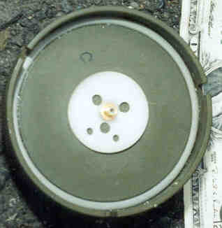 |
Fig 6 Magnet for tamper switch inside battery
cap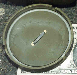 |
Fig 7 Interrupt
Control Assembly [16] |
Fig 8 Control switches |
These are the TC series modules used in a number of the intrusion detectors.
Field Programmable Code Plug [14]
The factory programmed "TC432 Code Plug" has been replaced by a special one that has plugin jumpers (resistors?) to allow setting:This Code Plug is used on the actual field units as well as the training units. It allows field programming of the code.ID (6 bits) [18 contacts] Data Rate 75 or 300 baud (1 bit)[ 2 contacts] Gain: Lo, Med, Hi (3 bits, single ended)[6 contacts] Spare (1 bit)[3 contacts] Parity (1 bit)[3 contacts] There is also a glass tube[2 contacts] that looks like a magnetic switch as is used in burglar alarms. There is a magnet in the bottom of the cylinder and the code plug goes into the bottom of the hole. This is a poor design because you can pull out the transmitter module and leave the code plug in the bottom of the hole. The ribbon cable almost locks the code plug into the hole.
There is a 16 wire ribbon cable going from the "Programmable Code Plug" to the main electronics that are in a clear plastic potting. The colors are:
Brn, Red, Org, Yel, Grn, Blu, Vio, Gry, Wht, Blk, Brn, Red, Org, Yel, Grn, Blu.The 92-pin connector is marked TA386. This is the same marking that is on the female connector with wires coming out on the GSQ-160.
TA386 is the nomenclature for the raw 92-pin female connector. On this one the B coax is there and the A, C and D positions are empty.
Encoder Module TC431 [13]
Transmitter TC434 [12]
The Disable function is aimed at the transmitter. The "For Test and Training Only" version of the GSQ-154 has the disable wire open prior to the transmitter module. The transmitter module used in the GSQ-154 would still have the disable function active.
This cap has an SMB connector that mates perfectly with the output connector of the "TC560 Transmitter".
There is a shoulder strap that connects to 2 wire loops for carrying the GSQ-154. There is a pouch in the strap with an antenna 16" long that will screw onto the "bolt" on the transmitter end cap. Although it looks like a threaded bolt there is continuity to the center of the coax connector and open to the metal end cap shell. I think this is an active antenna connection.The lugs on the end cap are arranged so that it can only go onto the housing in one position. This will insure that the antenna points to the same side as the switches. There is a 5/64" Allen set screw that locks the end cap in place so that soldiers will not open this compartment.
The antenna is 16 3/8" + 1" for antenna effect in the cap = 0.446 meters. 300/(4* 0.446) = 168 MHz which is the center of the 162 - 174 MHz transmitter range. The antenna is stored in the shoulder strap. The compartment also has a metal blade to help protect the fragile whip antenna.
A 28 Volt Mercury battery is used.
The battery compartment is a cylinder that is 7" long 2.80" I.D. (that matches the cylinder for the TCxxx components).
The battery compartment is only 4.75" deep, the seismic module is in the bottom of the battery compartment. There is a spongy grey foam donut in the bottom of the battery compartment so I expect that the battery is a cylinder shape and the other white stiff foam part was just packing material.
Inside there is a connector very similar to those used on a 9 Volt battery, except the connectors are on 0.9" centers and regular 9 Volt batteries have their contacts on 0.5" centers.
There is a 4-wire ribbon cable leaving the battery connector:The component appears is another magnetic actuated alarm switch. There is a magnet visible inside the battery compartment lid [1] and the magnet strongly effects a compass.
- Brn - component
- Red - Male bat connector
- Org - Female battery contact
- Yel - component
This is a cylindrical black plastic module that contains some signal processing electronics associated with the geophone.
This is the clear plastic assembly that is between the two tubes.
Allows use of external battery and auxiliary sensor. Life exceeds 30 Days.
There is a pin installed to prevent the main switch from being turned into the ARM position, only OFF and TEST can be used.
OFF - TEST - ARM [8]2 each 11 position Recovery Code [7] rotary switches marked: "Set 1 2 3 4 5 6 7 8 9 10 11" and "Set A B C D E F G H I J"
These switches have the same function as the 3 switches on the GSQ-160. This one is set to recovery code C-4.
Instead of lifting the ARM switch as on the GSQ-160, the label plate is made of springy metal and can be pressed down, lowering the stop pin and allowing the switch to go into ARM. Once in ARM the switch is locked there, thus preventing the Disable signal from acting.
There are 2 tags attached and each has English on one side and Vietnamese on the other.
AN/GSQ-154 (V) INSTALLATION AND RECOVERY INSTRUCTIONS - 5' x 6"CONFIDENTIAL WHEN FILLED IN - 4" x 3"
TM 5-6350-255-13 (025976.pdf)Brooke's: PRC68, alphanumeric index of web pages, contact, Products for Sale (made by Brooke), Home Page
Alarm Set, Anti-Intrusion
Restricted Area, MINISID III, AN/GSQ-154 (V)
NSN 6350-00-182-7653, and AN/GSQ-154A (V)
NSN 6350-00-160-0293
Headquarters, Department fo the Army July 1975