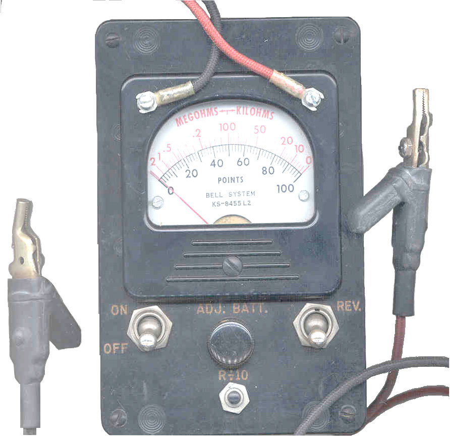
KS8455L2 Line Loop Tester
Kick Set
Telephone Installers & Repairman's Meter
© Brooke Clarke 2003 -
2014
Description
This is a current product for the
Simpson Electric Company. It has been optimized for testing
phone lines. The same tests could be done with other
instruments, but with considerable more difficulty and probably
other instruments would not be as a rugged.
I can remember in the 1950s the "telephone company" man
(there was only one then, company that is) using this meter as his
standard tool.
When the "phone man" came to our house he would check for the
number of ringers in our house and he had paper work saying how
many phones we were paying for. I soon learned how to
disconnect the ringer of a phone and add it to our line.
These were typically either 500 type dial sets or later 2500 Touch
Tone sets, where the polarity mattered. If you had not
signed up for touch tone and you house was wired properly by "the
phone company" then installing a touch tone phone would not work
because the polarity was reversed from standard practice.
Since it really didn't matter to the dial phones the easiest way
to become touch tone compatible was to just reverse the pair going
into the house, then a touch tone phone would work anywhere.
These were the days when the standard phone connector was a 4 pin
plug. Much larger than today's modular connector.
This may also be known as the Northern Electric 324.
Is very similar to the TS-26 militry test set.
Operation
Volts
It's recomended to start any test sequence by
connecting the meter to the line and measuring voltage.
This way you can confirm that the line either is or is not
powered. If the line is powered when you think it is not,
the other tests will be invalid.
1. Turn "OFF" to read volts on "POINTS" scale (i.e. 0 to 100 VDC)
Ohms
1. Turn meter on
2. Short leads
3. Adjust for red zero reading
4. Measure Ohms on red top scale
Distance
1. With meter "ON" and calibrated for Ohms
2. Switch back and forth the "REV" switch and note the POINTS
change in reading
3. Distance (feet) =480 * # of POINTS change
Note: if the meter deflects off scale try using the BAT
ADJ control to bring it back on scale, if this does not work
then press and hold the R/10 button while switching back and
forth.
Normal active line
1. One side (Tip) should have low resistance to ground.
2. The other side (Ring) should show about 50 VDC to ground
Detecting a bell
1. Disconnect line from telco Central Office (CO)
2. Measure Distance to tel set on ring wire (note # of points)
3. Measure Distance to tel set on tip wire (note # of points)
4. Connect leads to Tip and Ring and measure Distance
5. The # of points will increase by about 30 points for a
conventional bell (40 points=.464 microfarads)
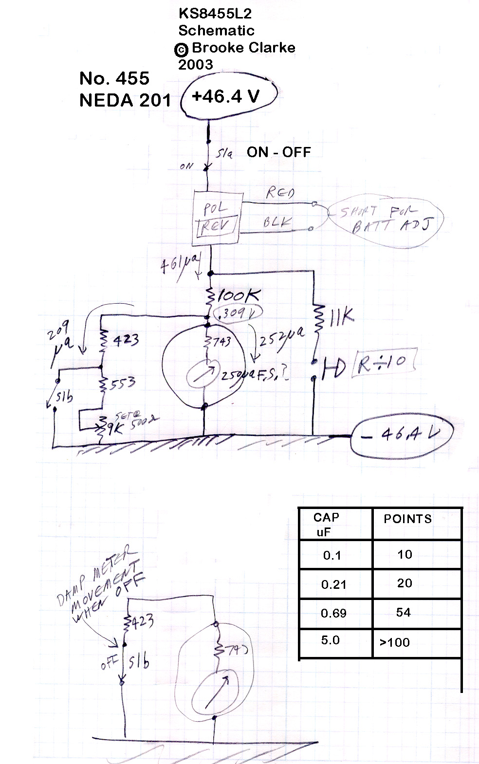
Measured:
Cap
uF
|
Points
|
0.1
|
10
|
.021
|
20
|
0.69
|
54
|
5.00
|
>>100
|
Locating an open with Distance measure
1. Disconnect from telco Central Office (CO)
2. From one end of pair measure Distance on Ring
3. From one end of pair measure Distance on Tip
4. If readings are about the same both wires may be open, if
different one wire may be open
5. From other end measure Distance on Ring and Tip
The percent distance to the open is the distance from one end
divided by the sum of the distances
Ground Connection
For a number of tests the instructions say to connect
one of the test leads to ground. If a ground wire is handy
this is easy, but often only dirt is available. In this
case just plunge a screwdriver into the ground and clip onto it.
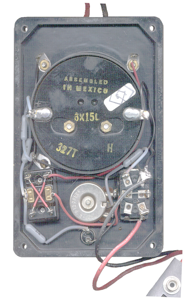
Battery
Eveready No. 455, NEDA 201, 45 Volts, Radio Shack
960-0445 45 Volt
Manual
The Bell System Practices for the meter is: Outside Plant
Construction and Maintenance, Section G10.400, Issue 1,
August 1941.
Simpson -
Test
Instruments -
8455
Line Loop Tester -
manual.pdf
-
this
manual
conatins test methods for many more line tests than are listed
above, but does not include checking for ringers. The manual
does not include a schematic diagram. It mentiones that on
the later models the REV switch was easily replaceable and could
also be changed to a push button, which would be much easier to
use for measuring distance.
Back to Brooke's PRC68, Products for Sale,
Telephones, U229 Audio Accessories,
Audio Connectors, Military Information, Electronics, Personal Home page
page created 2 July 2003.