6 Digit Display LED1 & PIC 12F675 Clock PC2
© Brooke Clarke, N6GCE |
|
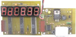
| The white rectangle is styrofoam covering the DIP oscillator |
LED1
This is a 6 digit LED display that uses 0.56" high 7-segment LEDs and Allegro 6276 LED driver chips. The input is serial data, clock, Output enable and Latch Enable, ground and +5 Volts. These same signals are output on the left side so that as many of these boards as desired (and the power supply can support) can be stacked to form 6, 12, 18, 24 etc. digits of display.
There are some options on how the board is powered so that the power dissipated in the driver chips is minimized. These each chip has a current set resistor and all the LEDs have individual current control in the chip. This is a static LED drive that will produce the brightest and most efficient way of running the LEDs. There is no multiplexing of the digits so a camera will see all of them.
There is an option allowing either the MSB decimal point to be active or that bit can be turned into a TTL signal, such as for a 1 PPS TTL output.
The design will scale to much larger digits or custom arrays of LEDs since each LED is driven separately. Series strings of LEDs, like are used in the larger display digits or custom made LED displays incorporating series strings up to about 17 Volts can be used with the design.
When the Rext resistor on each of the Allegro 6276 chips is set to 1k0 Ohms the nominal current in each LED segment is 20 ma. This makes for a very bright display and the current draw typically is 600 ma, more than the HP 6216A power supply can provide, switched to the E3617A that's good for 1 Amp.
The LED1 display can be unplugged from the PC2 with power applied and hot plugged back in, and the PC2 clock keeps the time.
PC2 Clock
This is a PIC 12F675 based clock that has a number of interesting features:
- On board LDO 5 volt regulator that is driven two ways:
- through a full wave bridge for primary AC or DC sources.
With >= 8.0 VDc on the bridge input there is no current drawn from 4 each Alkaline "D" cells connectod to the single Schottky backup supply.
- through a schottky diode for battery back up.
$ Alkaline "D" cells rated for 18 AH will power the clock for 30 hours with the LEDs pulling about 600 mA, a very bright display.
When the backup supply voltage goes down to 5.22 V the center two digits go black, at 5.08 the right two digits go balck and at 5.01 V all the digits are black, but the PC2 clock is still running with 3.78 Volts on the PIC and oscillator. This is with a 1N4002 in series with a Schottky 1N5819 between the +5 V rail and the common LED anodes, bringing the anode rail to 3.34 V to minimize the power dissipated in the 6276 chips. There is a tradeoff between minimizing the power in the 6276 chips and the shut down voltage for power failure. Now there is about 1.4 Volts across each 6276 output transistor when the segment is on, so if all the segments were turned on there would be 8 * 1.4V * 20 ma = 0.22 Watts dissapated in each 6276 chip which should be good up to about 137 deg C ambiment temperature, very conservitave. The LEDs are running warm and the 6276 chips are cool.
The regulator is always providing voltage regulation to stabilize the unit oscillator.
22 March 2003 - The bugs in the LED1 and PC2 printed circuit boards have been fixed and the hardware is operational. The software definition tables for LED segments needed to be changed to match the wiring of the LED1 board. The photo showing "AdC833" was retouched to make the display more visible. The A/D converter is reading the thermistor under the DIP oscillator, now with a simple styrofoam cover. Need to get some red plastic for a filter.
- 14 DIP outline unit oscillator provides the clock for the PIC and is the source of time. A thermistor measures the temperature of the unit oscillator so that it's frequency can be corrected.
- On the prototype board the Latch Enable line going to the LED1 display is tied to +5 Volts so that only 3 I/O pins on the PIC are needed: Data Out, Clock Out and Output Enable.
- LED connected to PIN 5 for heartbeat confirmation.
- The edge connector not only can drive the LED1 display board, but also can be used with the Microchip ICD2 for programming the PIC allowing production versions to have the PIC soldered to the board instead of in a socket (for prototyping). The edge connector also has one of the switches brought out so that it can be pressed by a computer allowing automated calibration.
- This same board can be used for a number of 12F675 based products either as is or by special assembly of components or mainly by a mating board or cable.
31 July 2003 - the temperature controller that was holding the aging test chamber at 40 deg C. died.
The Sentry oscillator followed the following curve:
Frequency (Hz) = 20 MHz - 35.858*Ln(minutes) - 84.952 the R2 fit for this equation is 0.9922 over 5+ months.
22 Aug 2004 - The sentry has been well behaved and the current equation is:
Frequency delta from 20 MHz = -64.932Ln(minutes) - 250.95 R2 = 0.9865
Rather than use a linear regulator, it would be better to use a Buck Switching Mode Power Supply with an output of 3.3 Volts. The PIC and unit oscillator should run from 3.3 Volts as well as the LED display. This way the complete clock could run from a very wide range of input voltages, i.e. 4 to 60 Volts. If a linear supply was used with this input voltage range the power dissipation would be very high at 60 Volts in. Battery backup can be any voltage that's above the minimum input voltage and below the normal input voltage using a simple diode OR function.
22 Aug 2004 - Rather than use a unit oscillator, using a lab grade oscillator as the clock source for a microcontroller would allow:
Moving the 1 PPS edge might be able to be done by setting an offset value into a single microcontroller, but would be better if done by a seperate chip and display that would be a fixed delay time generator.
- converting a good frequency source into a good clock
- generation of a 1 PPS output to allow testing time differences.
Precision Clock 1 page with earlier work in this area
11 April 2007 - Altough a clock like this can be built the problem is that I wanted many more features. When the number of characters in the display goes up LED type displays are no longer cost effective. LCD displays allow many more characters for little more expense. So it's a trade off, you can have a small number of characters (like a 6 digit clock) with big and lighted numbers by using LEDs or NIXIE tubes, but when you want many more characters the LCD is the way to go. For the current PC4 clock using a 2 row x 16 char LCD.