Platoon Early Warning System PEWS
AN/TRS-2(V)
©Brooke Clarke, N6GCE 2004 - 2022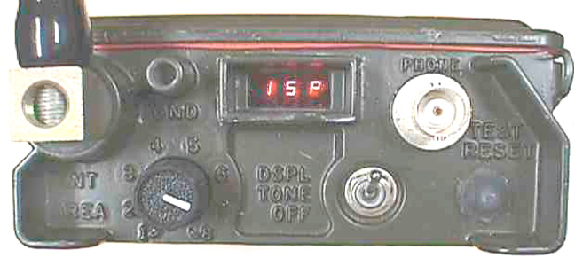 |
|
Troops in the field need a small portable intrusion detector so they can be alerted when enemy troops get too close. First used in 1980. This is one of the outdoor intrusion detectors that's used for that purpose and others. PEWS is obsolete as of 1992 and has been replaced by the GSQ-187 REMBASS system. My guess is the REMBASS can use satellite links to monitor the sensors making it a very much more powerful system.
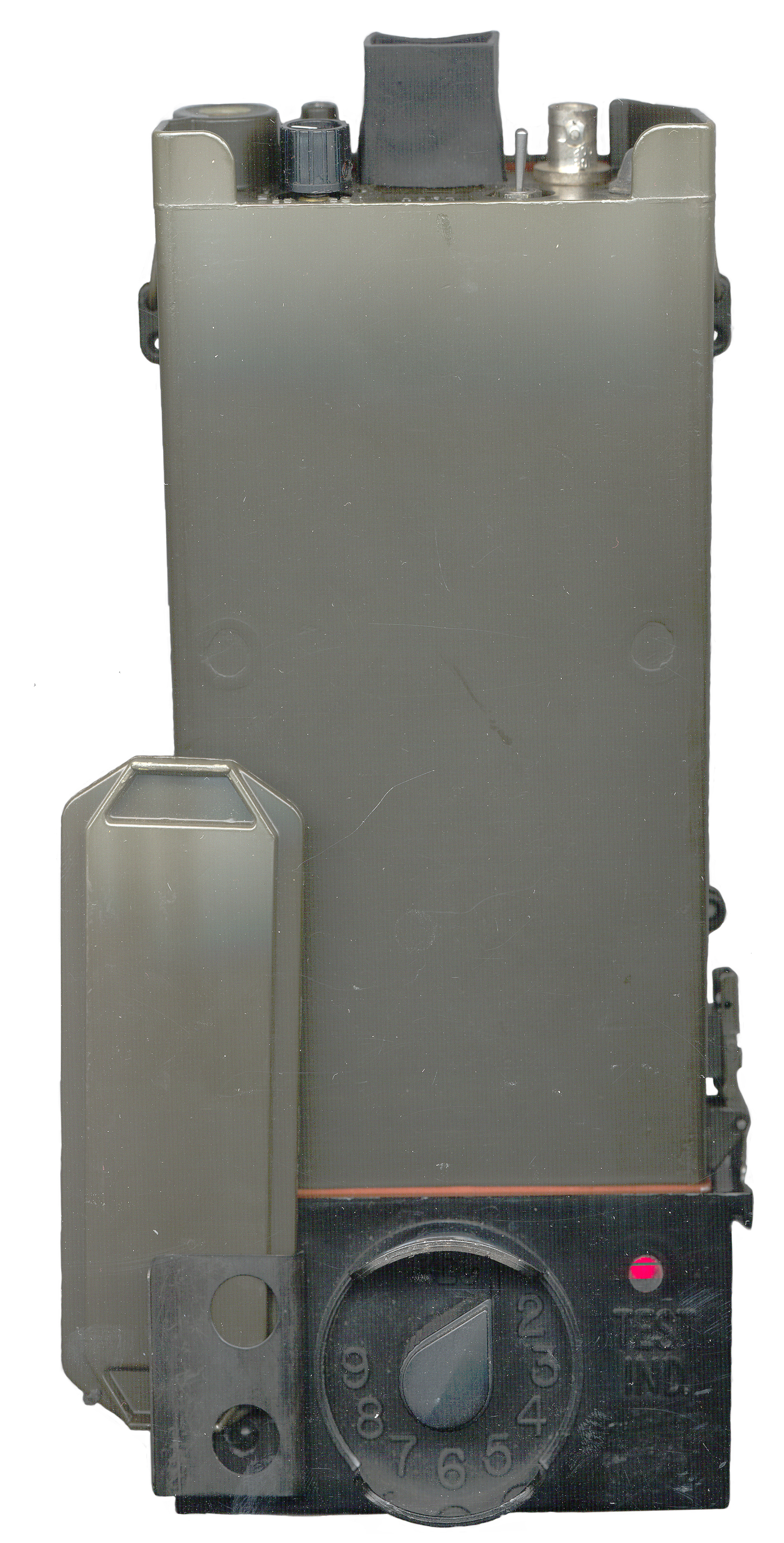
DT-577 Sensor Transmitter
The DT-577 sensor responds to both seismic and magnetic disturbances. These are sent to the transmitter either with an RF signal or by means of a pair of field wires. In order to use the RF method both the DT-577 sensor and the R-1808 receiver need to be on the same frequency, i.e. have the same suffix number (between 1 and 6).
The data sent to the receiver is different for seismic and magnetic events. If both types of events occur the sensor sends two messages to the receiver.
Before a new sensor can be used it needs to have one or more of the wires in the battery compartment clipped to program the Area and ID number of sensor.
The switch on the sensor allows for either RF transmission of alarms or Wire line transmission.
An unused sensor will have all of the programming wires in the battery compartment uncut. This is not a valid area and sensor number.
I just cut the red parity wire and now my sensor is set for area 7 (4+2+1) and is sensor # 15 (8+4+2+1) and since there are 7 wire loops (ones) the red parity wire needs to be cut to get an odd number of ones.
In order to receive warnings the receiver must be set to area 7. It will NOT alarm on other inputs.
Re-Crystal Transmitter submitted by ____
Access
The electronics are accessed by removing the code plug and battery connector. Remove the two sheet metal screws near the connector in the battery case, and then remove the 8 machine head screws that hold the cover on. Run an X-Acto knife between the cover and the case, cutting through the RTV seal, and gently pry the cover from the case starting from the end opposite the connector. Don't separate it too far before unplugging the two leads to the geo-sensor. Remember that the black wire goes to the pin closest to the sensor. The crystal can be changed at this point. If you wish to re-align the transmitter, continue on.
Adjusting
The next step would usually be to key the transmitter and use a service monitor to fine-tune the frequency and maybe peak-up the output stages, but the PEWS transmitter sends only very short bursts of data, and there is a circuit that prevents re-triggering for five seconds, making CSM use difficult.
However, disconnecting the ribbon cable between the two boards causes the unit to transmit a sequence over and over. Further, by grounding certain pins on an IC on the board on which the transmitter circuitry is located, we can cause a steady dead carrier, or a steady carrier modulated by either 1500 or 1800 Hz, (the two tones used for transmitting data).
Attached is a (rough) drawing of the component side of the "radio board" in the PEWS detector/transmitter showing the IC and points to ground.
R-1808 Receiver
The R-1808 receiver will receive the signals from the sensors either by means of the Antenna or a wired connection. When the receiver receives a seismic event a "P" ( maybe for Person) is the right hand character, and if a magnetic event the right character is a "C" (maybe for Car).
It's not clear if a receiver will receive both wire line and RF inputs. There are only 3 connections between the Wire Link and the Receiver and I doubt that the receiver knows that a Wire Link is attached, so maybe it will respond to both RF and wire signals at the same time?
MX-9738 Wire Link
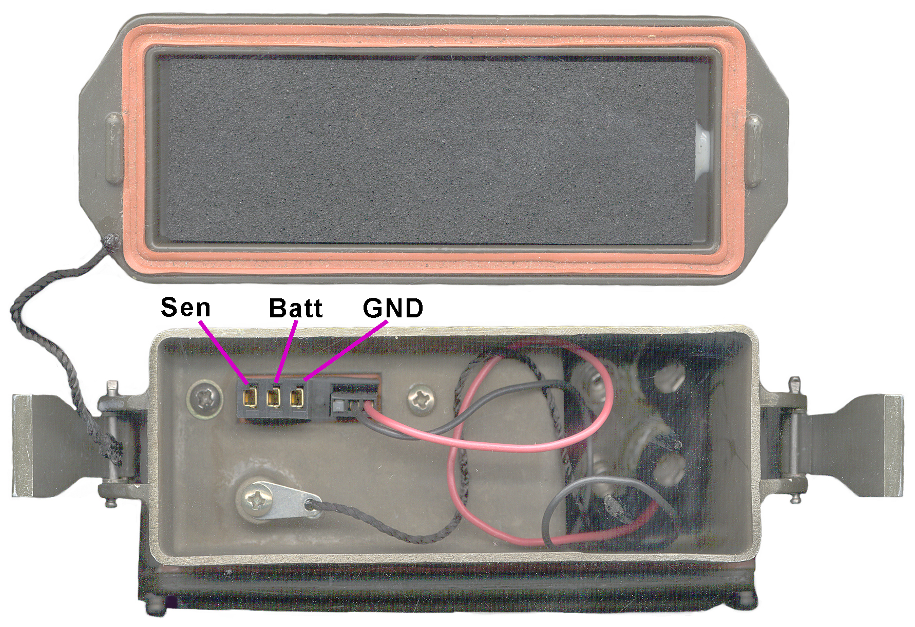
In order to use the field wire method the receiver needs to be fitted with the MX-9738 Wire Link Interface. This interface fits between the battery cover and the body of the R-1808 receiver and has a rotary switch labeled REC and 1 through 9. The REC position is used what the system is operating and connects all the sensors in parallel. The numbered positions are for testing the integrity of the wire. If the light on the Wire Link blinks when in a numbered position that wire is either open or shorted.
As shown above with the battery compartment on the right the 3 sockets are left to right:
This means that all the wire lines are combined into a single signal into the receiver. Having the 9 positions is only for testing the integrity of the sensors.
- signal from wire line adapter after going though a differential amplifier and squaring circuit (upper and lower voltages?),
- the Battery Voltage to power the Wire Link,
- and Ground.
The MX-9738 is in a plastic housing that's been cemented together, making it difficult to determine what's inside. The label says:
PLATOON EARLY WARNING SYSTEM
MX-9738K/TRS-2(V) SN 00074A
CONTR. NO. DAAB07-85-C-E633
WIRE LINK SENSOR INTERFACE
DES. ACT: 56977 MFR: 54125
5895-01-075-0071
When the wire line adapter is connected to the receiver there is a clip on the wire line adapter that holds the battery box cover. If the wire line adapter test switch is set for line 1 to line 9 a red LED flashes indicating that there is a defective circuit. This happens for both open and shorted circuits.
If you have any documentation on the wire link about it please let me know.
TM-11-5895-1047-10 pdf page 51 (2-32) has a diagram showing three sensors wired in parallel forming a "Hot Loop" system.
PEWS Set
A set consists of the R-1808(V)x receiver and ten DT-577(V)x Detectors plus misc. other items. (the x is the version number and indicates the RF frequency as follows:Note that all the frequencies are below the sonobuoy 160 to 176 MHz range of the USQ-46 sensor receiver. They are in the 100 to 150 MHz aircraft radio band. It's also interesting that there's a satellite band centered on 150 MHz.
The set can also be used in a wire line mode with the RF mode disabled. The DT-577 Detectors have both seismic and magnetic sensors. The magnetic sensor has a sensitive axis and the DT-577 has an arrow to be aligned parallel to the path or road. You do not get to hear the sub sonic sounds with this unit, it only sends a digital byte of data with the area and sensor ID and the type of detection, either seismic or magnetic. If a deer sets it off the audio signal in a receiver sounds the same as if a man set it off. You can not select either magnetic or seismic, you must always have both. I would like to have magnetic only - no deer would set it off. There is NO sound from the receiver, only a digital byte or two is sent, so you can not "hear" what's happening like you can with the analog PSR-1.
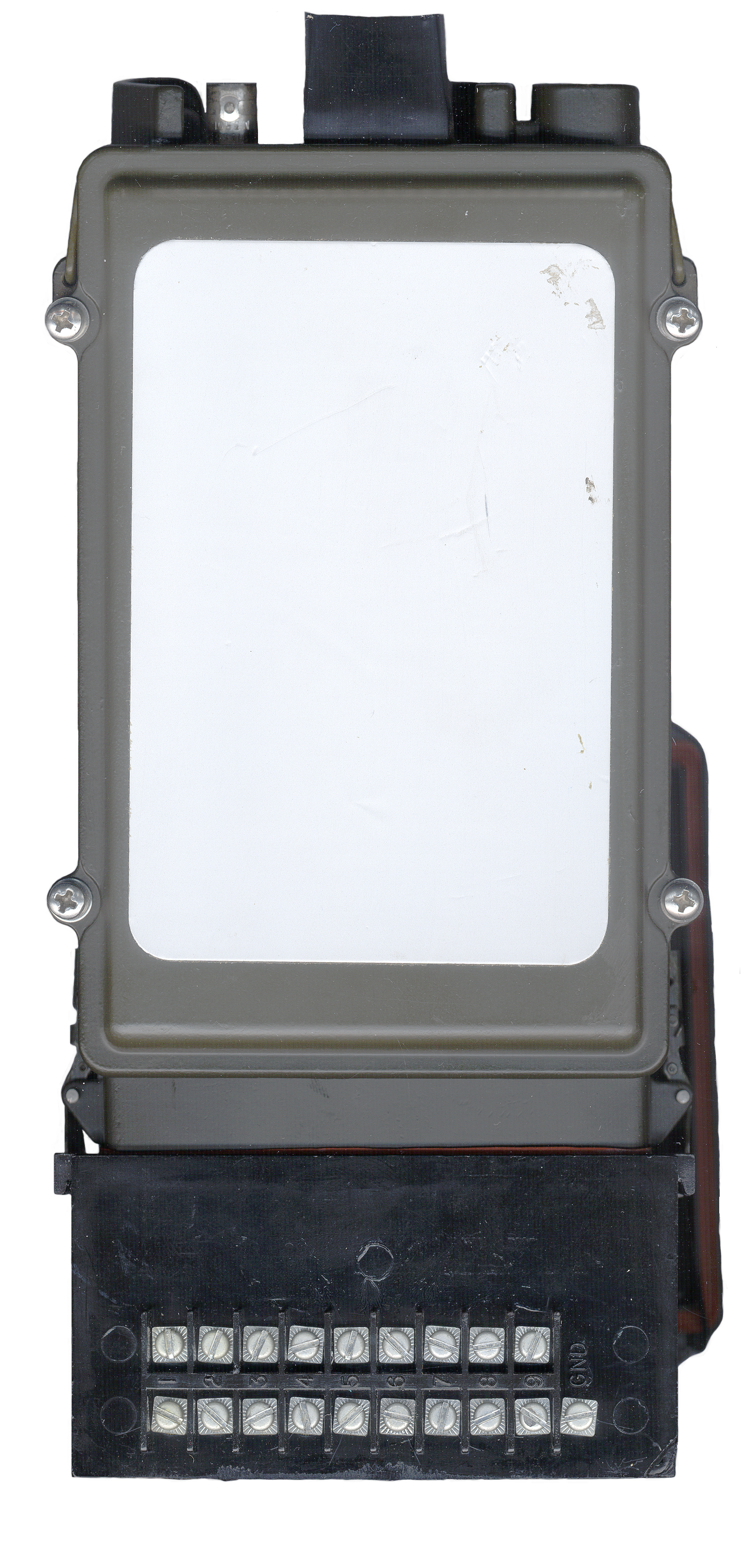
DT-578( )/TRS-2 PEWS
This showed up on eBay Oct 2022. Label:
PEWS
DAAB07-74-C-0573
Detector, Anti-Intrusion
DT-578( )/TRS-2
Freq. 148.925 s/n:
Delco Electronics Div. GMC
Area: I.D.
Toggle switch on top for: RF-Off-Wire
It has three push down to open telephone type wire terminals two labeled DATA and one labeled SC. What does the SC terminal do? Let me know.
The following information comes from TM 11-6625-2784-14 Paragraph 1.8 Tabulated Data. Figure 6-2 shows the envelope of the signal, it has a 10 ms period of 1800 Hz as the start indicator of each 30 ms bit period. The center 10 ms is 1800 for a "1" or 1500 Hz for a "0" and the final 10 ms of each period is 1500 Hz for the stop indicator.
The signal sent over the wire and that FM modulates the R.F. carrier is Frequency Shift Keyed (FSK). The low frequency is 1500 Hz and the high frequency is 1800 Hz. There is 1 start bit, 3 area bits, 4 ID bits, 1 odd parity bit and 1 classification bit (for magnetic or seismic) for a total of 10 bits. The clock rate for the data is 33.33 Hz or 30 milliseconds for each bit.
The Wire Link receives the wire line signal in a differential amplifier so as to reduce any common mode noise and then squares it up with a zero volt threshold detector. The wire line signal is AC coupled. The signal going to the RF generator modulation input is AC coupled and has been LP filtered using a 1 resistor, 2 cap circuit.
A PIC micro controller would measure the time that the audio signal was high or low as the output from a frequency to voltage converter IC and thus have the input needed to decode the data words. It's not clear what happens when two or more D-577 sensors are connected in parallel to the same line. Are the sensors smart enough not to transmit when another sensor is already sending?
27 May 2004 - measurements using the wire line adapter. The wire line receiver does not need to be on for these tests.
The sensor sends the TEST message a few seconds after the button is released. The signal is a +2 to -2 Volt square wave during the data packet which lasts about 340 ms. When there's no activity the output is zero volts, probably from an open circuit (i.e. the output is tri state).
Triggering on the beginning of the data packet shows a square wave at 1.4 kHz.
The only way I have to look at the frequency is with a scope and delayed triggering. On the 1 ms/ time base the delay time can be up to 160 ms, NOT enough time to see the parity bit. But using a delay measured in trigger counts the delay can be much much longer.
With the delay set to 1 count the starting frequency is 1.4 Khz, not 1.8 kHz. The first 40 pulses (aprox 28 ms are at the 1.4 Khz rate).
With the delay set to 357 counts (all the proceeding bits at 1,800 Hz) the time delay is about 198 ms. And with the trigger point at center screen all 10 ms being displayed is the low frequency (about 1.4 kHz).
1 June 2004 - The data stream going between the Wire Line Adapter and the PEWS receiver is a digital wave form with the lower voltage 0.500 Volts and the upper voltage 8.4 Volts. This looks like one diode drop from a rail to rail swing for one of the 9 Volt batteries powering the PEWS receiver.
The width of the first pulse is 340 uS and the low portion is 336 uS. The frequency of the first on-off cycle is 1.462 kHz.
Caution
When plugging the Wire Line Adapter onto the PEWS receiver there are 3 pins on the wire line adapter that go into a socket on the receiver. Somehow the center pin pushed it's socket down into the receiver. To fix requires removing 3 printed circuit boards. It really was not a fix, since the next installation pushes the pin back down.
So be careful when installing the wire line adapter. If a pin gets pushed down you can see it by looking into the connector. Maybe with the right tool it could be pulled back without taking the receiver apart.
The key Technical Manuals are:Back to Brooke's Products for Sale, Outdoor Intrusion Detectors, Survival Equipment, Military Information, Home page
PEWS
TM 11-5895-1047-10 Operators Manual
TM 11-5895-1047-23 Organization and Direct Support Maintenance Manual
TS-3565 Test Set
TS-3565/TRS-2 can generate the digital messages like the sensor, but has no capability to receive data.
TM 11-6625-2784-14 Test Set, Receiver TS-3565/TRS-2(V) (NSN 6625-01-075-0046)
TM 11-6625-2784-24P Test Set, Receiver TS-3565
TM 11-6625-2784-14HR Test Set, Receiver TS-3565
The test set has capabilities similar to the TS-2963/USQ-46 Test Set except that the 3565 has only wire line outputs (an RF generator is needed for RF testing) and the data format is different. The PEWS equipment works with: Area: 3 bits, ID: 4 bits, Parity: 1 bit, Class (Seismic or Magnetic).
This is the [an error occurred while processing this directive] time this page has been accessed since since 2 Feb. 2004.