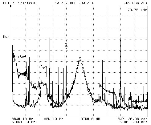
This is two plots overlaid. One is using the McKay Dymec DA-100 active whip antenna and the other the AMRAD active whip antenna.The plot with the lower noise floor at 0 kHz is the DA-100. The flat top peak on the DA-100 plot about 2 1/4 squares from the left is caused by this antenna being pretty much directly over my radio room by about 20 feet. Whereas the AMRAD antenna was placed on the ground about 90 feet away from the radio room.
The triangular peak at the center of the plot is Loran-C at 100 kHz.
WWVB is on the grid line 3 squares from the left. There is a very strong signal just below WWVB and another 2 strong signals below the very strong signal with the marker at 79.75 kHz.
These plots were made after replacing the power transformer in the AMRAD power supply after the XYL cut the cable with a lawn mower. The fuse was the wrong size (was 2.5 A should be 0.25 A). Also a couple of 1 mH chokes were installed between the transformer secondary and the power supply input, but they did not make much improvement over the 100 uH chokes that I added a while ago. It appears that a multi section filter would be needed to get the noise floor as good as the DA-100 below about 75 kHz.
This is the [an error occurred while processing this directive] time this page has been accessed since since 30 April 2001.