|
|
|
|
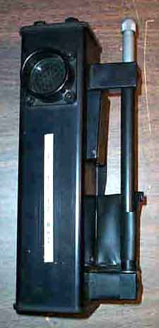
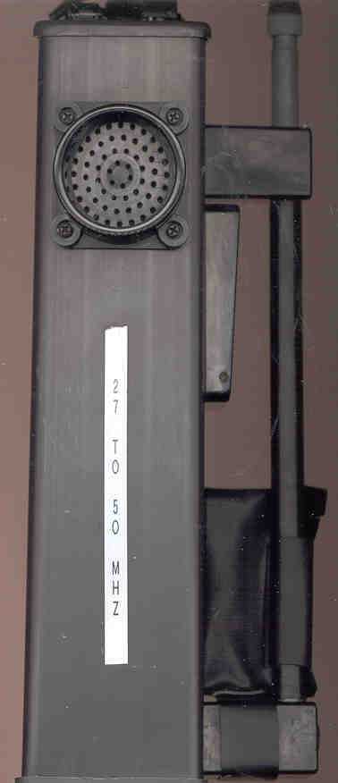
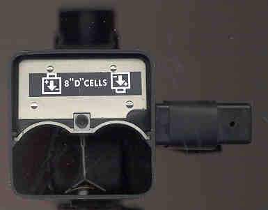
Runs on 8 "D" batteries. The telescoping antenna is 1 foot
long collapsed
and 6' 2" long extended. Someone has placed a label on the side
that
says:
" 27 to 50 MHz". How to change frequency? How to get a
manual
- instruction sheet?
This is most likely an HT-1E, since there have been a number of them on the surplus market."Radios by Hallicrafters" by Chuck Dachis, webpage -
OPS/Village & Hamlet Radios & System By Dennis Starks, Backmail #30
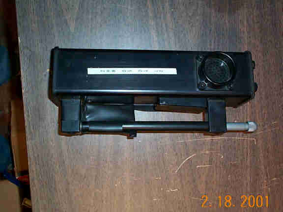
OPS Series Radios by Dennis Starks, (Mar.9/2001)Top Photo -
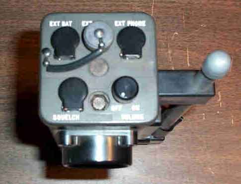
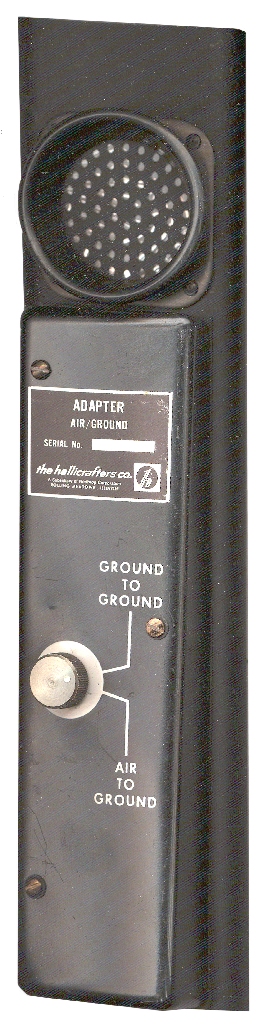
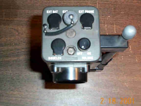
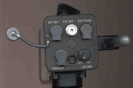
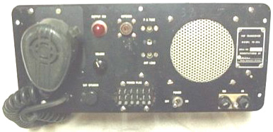
Top Photo2 - The EXT BAT connector looks kind of like a male RCA plug, except the male pin is much longer. If the large slotted screw is removed the top still seems attached by something, but what is not clear. How to disassemble this unit?Front Photo - At the base of the antenna is a small plastic pouch that now has nothing it it. What's it for? If the radio is held in the left hand (through the strap on the back) the Push To Talk switch is handy. Since there is only one audio opening I expect that it is a combined speaker/mike.
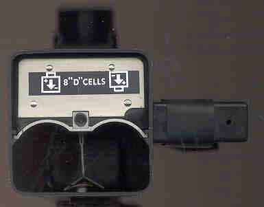
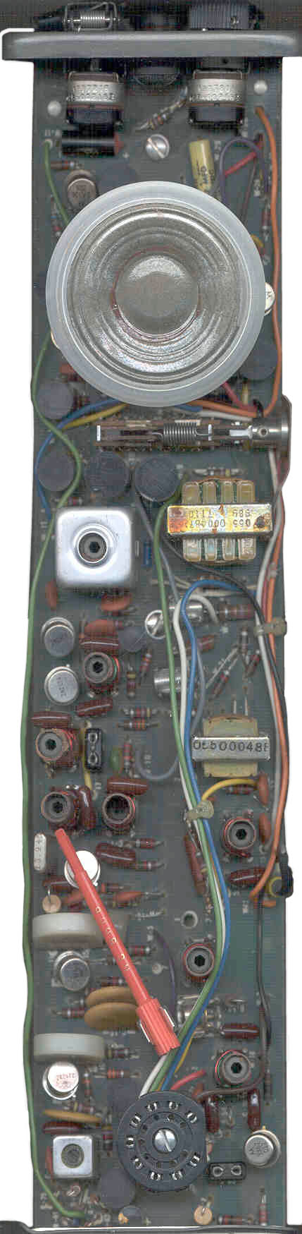
Battery compartment with cover removed. The battery compartment cover has a small allan wrench that can be used to remove the OFF-VOL control. At the bottom you can see the spring release sheet metal tab under the battery compartment separator. Lift this tab and press the chassis out the top.
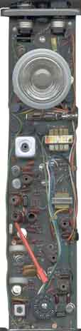
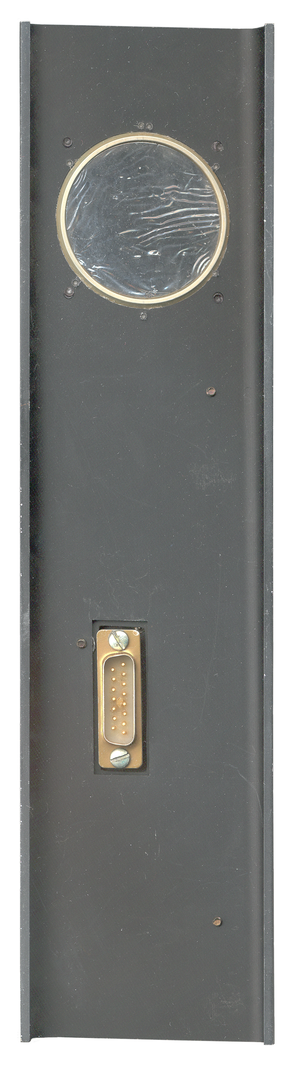
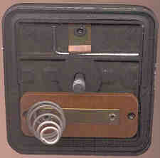
To remove the chassis, remove the bottom cover and inside on the back side there is a sheet metal spring that can be lifted. Then the chassis slides up and out of the case. The batteries can be installed with the chassis out and the bottom cover replaced to hold them. An external antenna can be connected to the SO-239 connector on the top panel. This would allow work to be done while the chassis is out of the case.
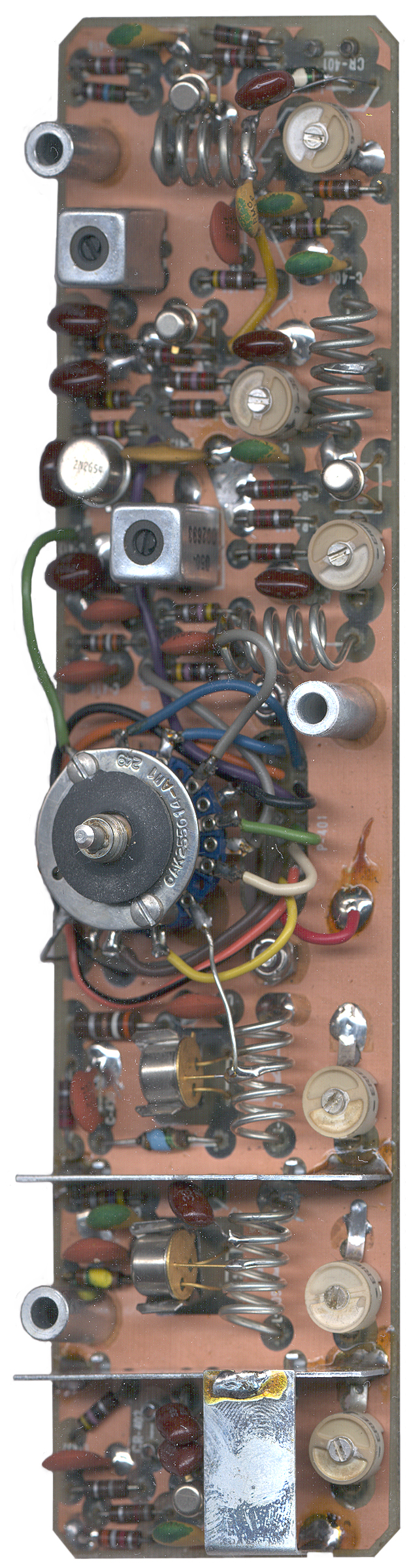
Just to the right of the large IF can there is a piece of string tied to one of the transistors that is on a heat sink. The string runs to the right side where it appears to have been cut off. This probably was a manufacturing tag that was carried with the radio and cut off before installing it in it's case. Note that there is no data plate on this radio by design.
In order to make these radios work, two crystals (Tx and Rx) need to be installed and the radio aligned (the red alignment tool is already in the radio.
- The 9 pin tube socket is for the TS-201A Test Set.
The test set is 4.5"x6"x5" (H/W/D), black in color, and has a removable lid held in place by fasteners similar to that used for the PRC-6 and PRC-10 cases. There are no nomenclature placards on the test set; however, a production order tag was included. The production order tag indicates that the test set number is TS-201A, made under production order 7822 at factory 38. The test set has two umbilical cords, one having a miniature 4 pin connector and the other being a nine pin miniature connector having the same form factor as the base of a 12AT7 tube base. There is a three position bat handle switch on the test set labeled XMT TONE ON, XMT TONE OFF and RECV and an eight position rotary mode switch labeled B+, BIAS, AGC BATTERY, PLATE CURRENT, 11.5T and AUDIO OUTPUT. The eighth switch position is not labeled. The test set also includes a multiscale meter.
JohnKA7AHJ
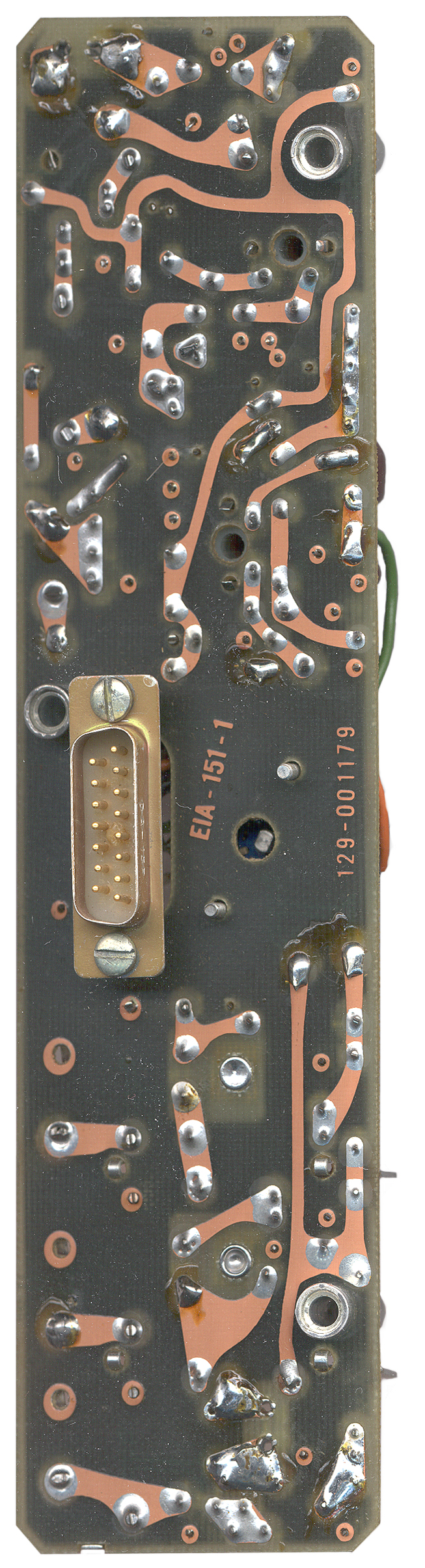
This radio is made using discrete parts, no IC's here. There are 12 Transistors, 3 mounted on small heat sinks. The radio uses 12V positive ground. The circuit board has all the traces on the bottom and all the components mount on the top.
Schematic Diagram.pdf - manual courtsy of Bob NickelsCrystal Instructions
Rx Crystal CR1 = Receive Freq (30 to 40 MHz) - 14.4 MHz
Tx Crystal CR3 = Transmit Freq (30 to 40 MHz)
The manual says that the Rx and Tx crystals are HC-6 packaged, but that's wrong.
They may be H-18 or S-18 or HC-25 packages, the c-c distance on the sockets is approximately 0.2 inches.If you have crystals for this radio pleas contact Brooke
The HT-1E Manual cost is $9.75 which includes shipping & handling .
A check will be fine made to:ARDCO ELECTRONICS
P.O. BOX 95
BERWYN, Ill 60402
 |
 |
 |
 |
| Component side PCB |
Front |
Back |
Trace side PCB |
| Pin |
1 |
2 |
3 |
4 |
5 |
6 |
7 |
8 |
9 |
10 |
11 |
12 |
13 |
14 |
15 |
| Color |
Blu |
Org | Blk |
nc |
nc |
Brn |
Yel |
Red |
Blu |
Blk |
Vio |
Grn |
Wht |
Org |
Gry |
| Where |
Gnd |
2N2654 |
Ardco Electronics, PO Box 95, Berwyn, Illinois 60402 has reproduction manuals.Back to Brooke's Military Audio, Squad Radio, Military Information, Home page
Village Radios by Peter McCollum
OPS Series, Village Hamlet Radios by Dennis Starks
Collection of Village Radios
HT-20J - eBay Photo -
This is the [an error occurred while processing this directive] time
this page has been accessed since since 25 Feb 2001.