ICOM 706 Mk II G
© N6GCE - Good Computer Engineer 2000 - 2013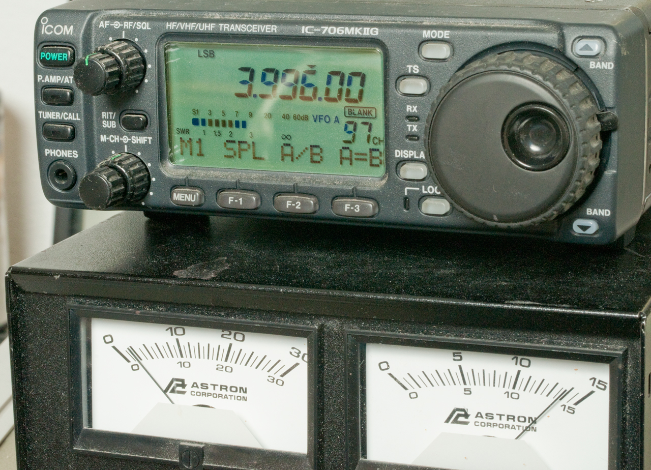 |
 |
|
|
With my upgraded General ticket I wanted an HF radio that: has computer control capability, that might be used for Automatic Link Establishment (ALE), that could be used for a beacon system, Small to fit into the Light Weight Beacon back pack.
The Ten Tec Pegasus and ICOM 706 were on the short list below for PC-ALE. The Pegasus currently has no front panel, but a FP model will be out in a few months. For computer use the front panel is of little value, but for programming (my interest) it sure makes life easier. The SGC - SG-2020 would be an excellent radio for this project, but it does not have computer control capability at this time. There is an SG-2020 Club. The Harris RF-3200 is another ALE capable mil radio as are the Harris 5020 series radios (like the PRC-138), or the Motorola Micom.
Icom has a land mobil (not ham) HF radio with built-in ALE. There are two versions I know of, the IC-F8100 and the IC-F8101. There is a difference in how external connections are made, the F8100 used an optional adapter box to end up with a few DB type connectors but the IC-F8101 has those same connectors all on cables coming out the back and so does not require an additional adapter box. A bigger difference is that the IC-F8100 needs that external box to hold the RapidM card, but the IC-F8101 holds the card inside the main chassis, so a much more compact solution.
1.6 to 29.9... Tx and receive 0.5 to 29.9.... MHz. Built-in ALE, but as of Nov 2014 it may or may not work. There's an optional RapidM third party data modem module that can be installed internally that also supports many flavors of ALE.
Yahoo IC-F8100 group.
I have not yet looked into an antenna for 2m & 400 - that's on a separate connector.
April 11, 2013 - Using TCI
651T antenna.
The SGC - SG-231 Smartuner® looks ideal for this antenna. The manual (online at SGC) has instructions for interfacing the 231 to the 706 so that the "Tune" function works. The 231 differs from the 230 in that the upper frequency limit is 60 MHz, thus it will work for HF plus 6 meters.
There is information on how
to
connect the 231 to the IC706 so that the "tune" function
works properly. The "smart tune PRO" accessory can also
be used with the 231 to allow control of when the tuner
attempts to tune. Note that the normal smart tune
accessory will not work with the 231, maybe because of a
difference in the connectors, the 231 does NOT have the
receive amplifier that's in the 230PRO. There is also an
option to allow receive operation in a straight through mode
(no tuner like would be the case for ALE) or with the tuner
working to improve reception at frequencies close to the
transmit frequency.
|
|
|
||
|
|
|
||
| +13.6 VDC in | PIN 1 | PIN8 | 13.8 VDC out |
| GND | PIN 2 | PIN 2 | GND |
| Option 2 Interrupt - Start ICOM Tune Sequence |
PIN 7 | PIN 9 | TKEY |
| Option 3 Bi-directional Data Line |
PIN 8 | PIN 4 | BDT |
Note that the 231 is an antenna Coupler not an
antenna Tuner. The difference is that a tuner
(the military might call it a line flatter) is a device with
coax inputs and outputs (maybe sometimes ladder line
in/out). It's job is to transform the impedance on a
transmission line to 50 Ohms to match a transmitter
output. A coupler has a coax input form the
transmitter but has a single terminal that has high voltage
insulation because it drives a wire (NOT COAX) that is part of
the antenna. A coupler is preferred because the VSWR on
the coax to the transmitter is low. In the case of an
antenna tuner the coax between the antenna and tuner has a
high VSWR and hence high losses. SGC has a lot of
practical information on their web site about how to correctly
use their antenna couplers.
|
|
|
|
|
|
| Red | J1 -1 | J10-1 | 13.8 VDC Power | |
| Black | J1-2 | J10-2 | Ground | |
| Green | J1-3 | J10-3 | Tuned Indicator | |
| Blue | J1-4 | J10-4 | Reset the coupler | |
| White | J1-5 | J10-5 | Hold (Locks coupler settings) | |
| Brown | J1-6 | J11-1 | VHF ?possible future enhancement, idea that did not work, who knows? |
JP3 |
| Violet | J1-7 | J11-2 | Option 2 (Option B) = Interrupt - Start ICOM Tune Sequence | |
| Orange | J1-8 | J11-3 | Option 3 (Option A) = Bi-directional Data Line |
The Internal Jumpers are:
There is a new model SG237 that is a 1.6 - 60 MHz design that
is smaller and lighter than the 231. It has one less
inductor and one less cap on the output for 1/2 million
combinations vs. the 4 million for the 231. The 231 is
also rated for more power. It's not clear about the
connectivity to the IC706 "tune" function.
The 231 is directly supported. The lower frequency
rating on the 231 is 1.0 MHz vs. 1.6 for the 237. The
237 comes in the normal type box and also as a raw PCB and the
third variation is mounted in a box that matches the SG2020
transcivier. The 237 only draws about 300 ma and the 231
about 500 ma?
(I tried to get one of the 230PRO models, but they have discontinued it, note this is NOT the same as the 230 Smartuner®! The Pro version has the ability to interface to a computer, my kind of a product.) If anyone reading this has a 230PRO I would like to hear how it works. brooke@pacific.net
April 11, 2013
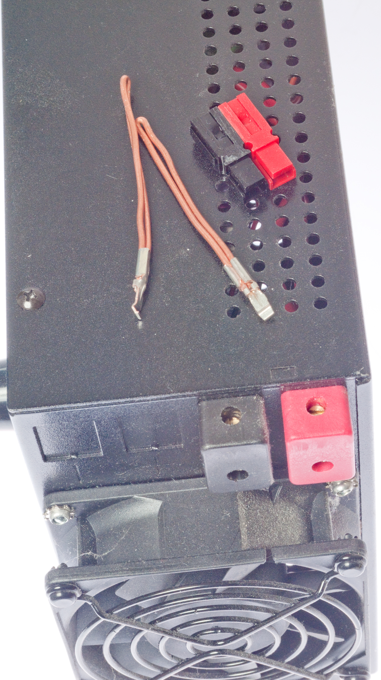
Added Power Pole connectors w/45 Amp contacts
My old linear 13 Amp 28 Volt supply weighs about 40 pounds and is not strong enough to power the PRC-47. It turns out that with the metering on the SS-30M that the PRC-47 could be powered by my older supply in the low power mode. There is a problem with the PRC-47, not the power supply.
The battery was on sale at Wal-Mart and is marked as a trolling battery, 115 AH. I am now working on the system of connectors to accommodate powering either of the two radios in many optional ways, as well as many 12 VDC items like GPS receivers. Note that the SS-30M has an internal strap between the black negative output terminal and the case & line grounds. This was added because some users had problems with RF interactions. I have lifted the PC board end and shrink tube insulated it so that the supply can be used in a floating mode because I plan to ground the negative terminal of the 12 volt battery.
I am using 6-20 connectors that the local hardware store has in stock. These are rated 250 V @ 20A. They have a ground terminal like on U.S. household grounded connectors but one of the blades is turned 90 deg. from normal and the other is a "T" shape. This will prevent anyone from plugging a normal AC type plug into the DC sockets. I am using the "-" terminal for 12 VDC and the "T" for 24 VDC, with the ground terminal for ground. Note that there is a 5-20 connector that looks very similar but has a different arrangement of terminals. For power sources like the battery and charger the socket is used. For loads like radios and inverters the 6-20 plug is used. This is the same convention used with most power connections so that it is less likely to have a short.
The battery will be charged and maintained by the Statpower - TC-10hw (Statpower calles it the TC-10tb, terminal block) smart charger. This is a mocroporcessor controlled charger made for marine use. The hw model is for hard wiring and can support two independent battery banks. It's a 10 amp unit but will charge faster than some higher amp units because of the smart nature of the charge.
Circuit Drawing DC.dwf
(Free Volo
or WHIP!
Viewer from Autodesk).
Xantrex (Statpower,
Heart, Trace & Cruising Equipment combined)
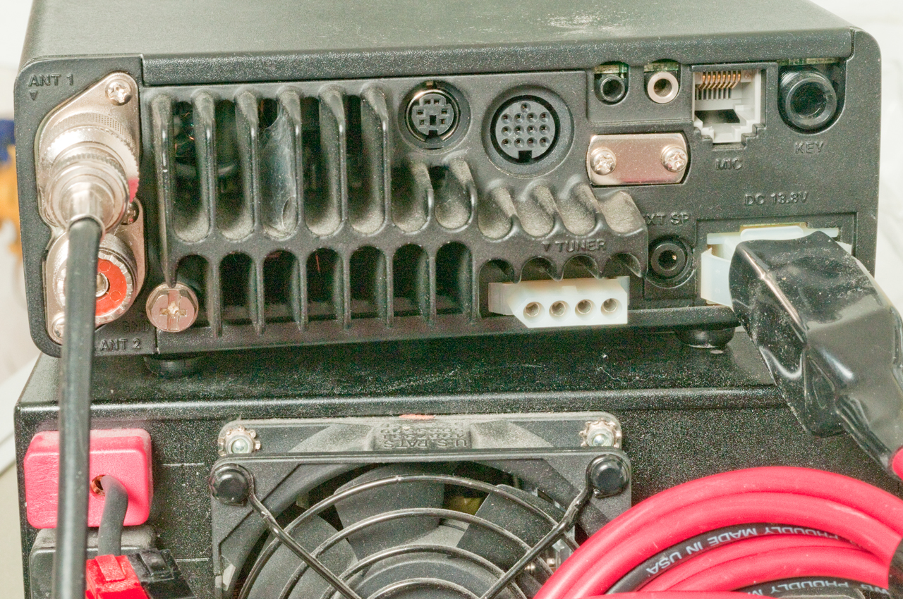
The stock HM-103 mike uses an RJ-45 connector and is a
powered condenser mike.
Connecting a military M80 or H250 dynamic microphone does not
work because there's not enough audio output.
An expedient microphone might be to use a Motorola unit and
install a new RJ-45 connector with the correct wiring.
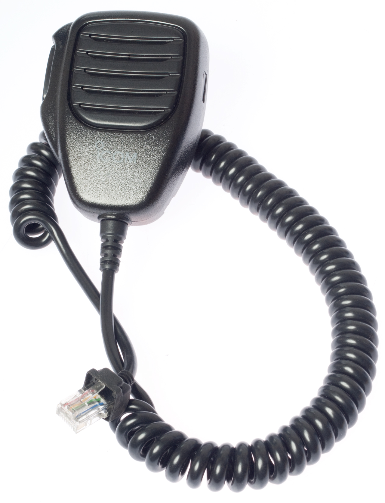
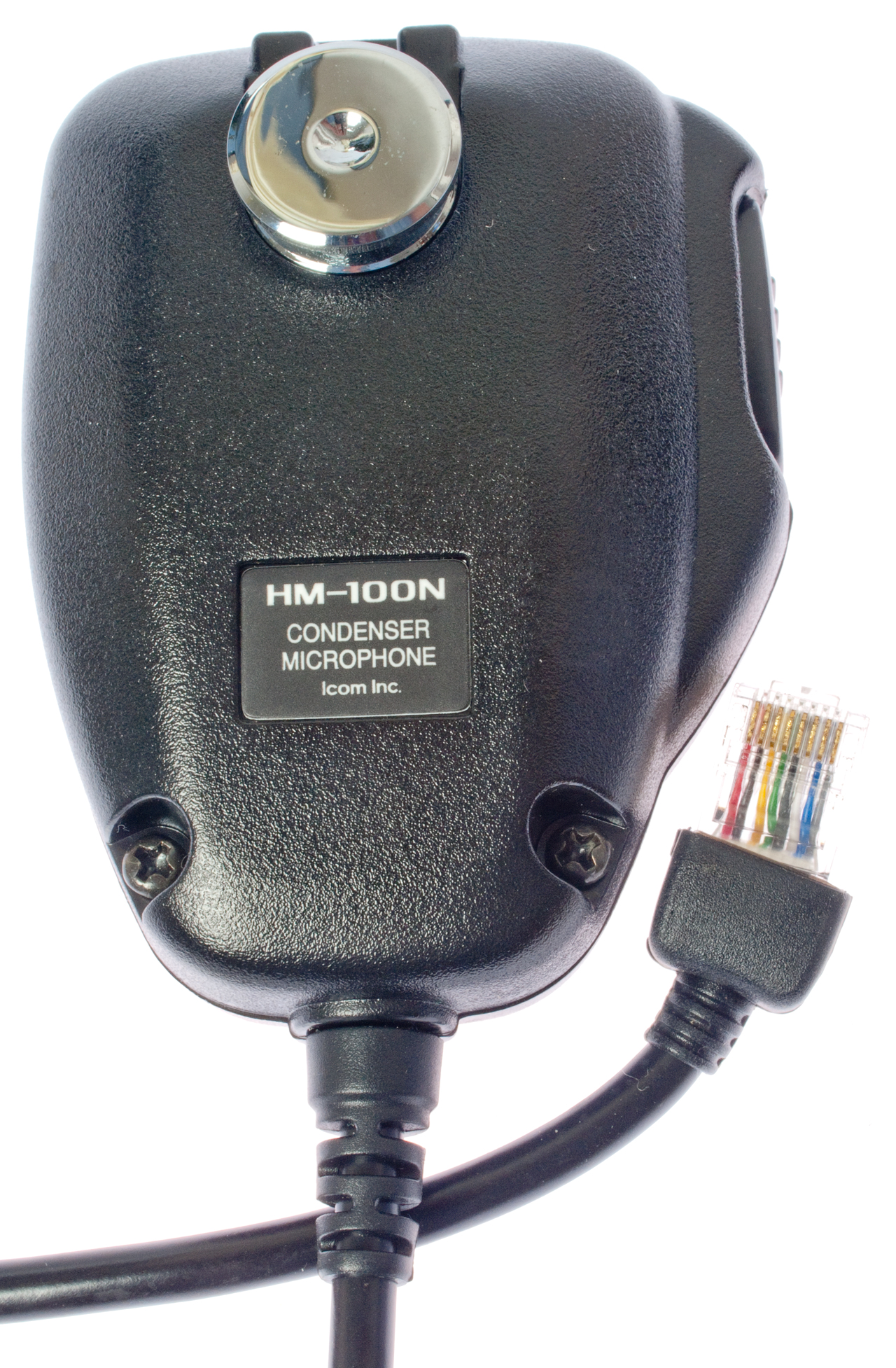
Icom HM-100N
The mike cord has an RJ-45 on the radio end and an 6P6C on
the mike end.
The PTT switch is connected to RJ-45 pins 3, 4 & 5
Between 3 & 5 you can see 550k Ohms, open, 0.75 Volts
Between 3 & 4 with no PTT you see open and with PTT
closed: 550k Ohms, 2 V
Between 4 & 5 with no PTT you see open and with PTT
closed: 5k Ohms, 0.74V
When plugged into the 706, keying PTT does nothing.
With the DMM in diode test mode there is no sound from the
mike with the test leads on any two terminals (PTT or/PTT), so
no dynamic mike element.
The Micom 2 mike is similar, but not usable directly on the
706.
The Micom 2 mide does not match the 1056D in the PTT area.
The pin out is:
| HM-103 |
RJ-45
Pin
|
HMN
1056D |
Micon 2 |
||||
| wire Color |
Function ???? |
Wire Color |
6P6C Pin |
Pin |
Function |
||
| +8V |
1 |
White |
White |
6 |
1 |
SW_A+ |
|
| Up/Dn |
2 |
Yellow |
Yellow |
2 |
2 |
RxD |
|
| AF Out |
3 |
Green |
Green |
3 |
3 |
TxD |
|
| PTT |
4 |
Red |
Red | 4 |
4 |
Gnd |
|
| Gnd |
5 |
Black |
Black | 5 | 5 |
Mic-audio |
|
| Mike |
6 |
Blue |
Blue |
1 |
6 |
PTT_Mic |
|
| Gnd |
7 |
nc |
nc |
na |
7 |
Monitor |
|
| Squelch |
8 |
nc |
nc |
na |
8 |
Audio_Out |
|
Fig 1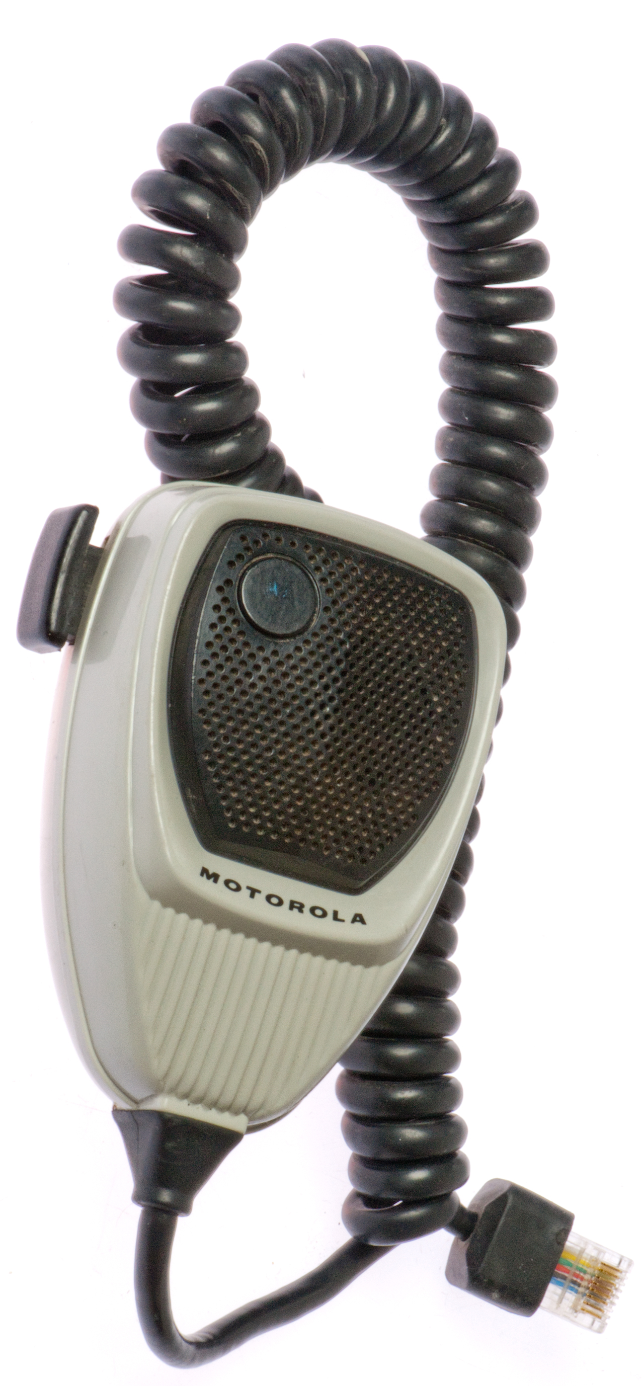 |
Fig 2 |
Fig 3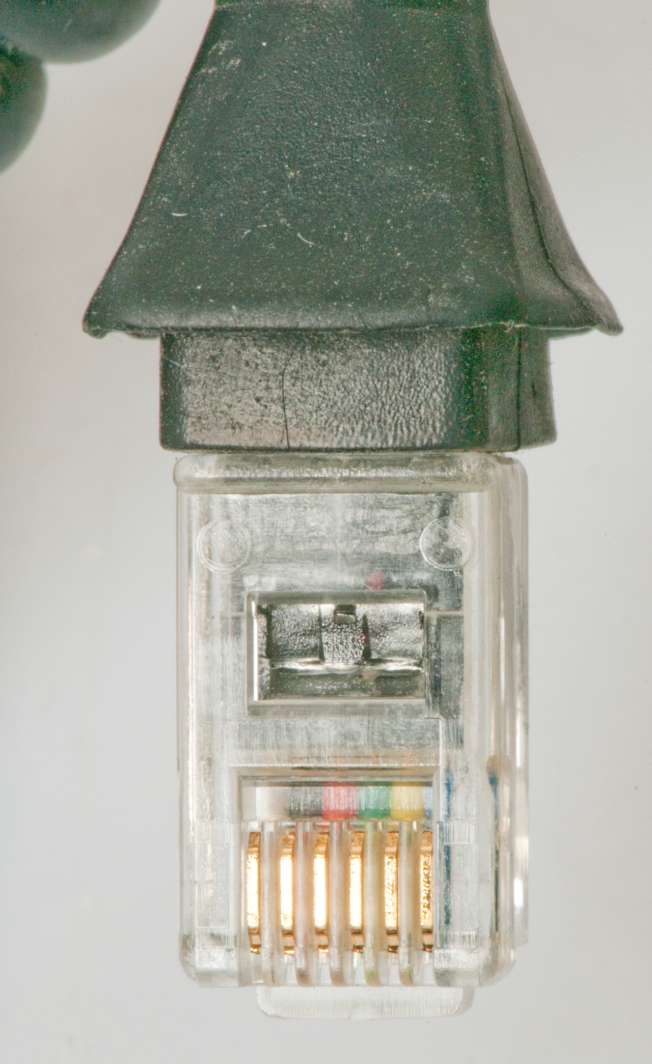 |
Fig 4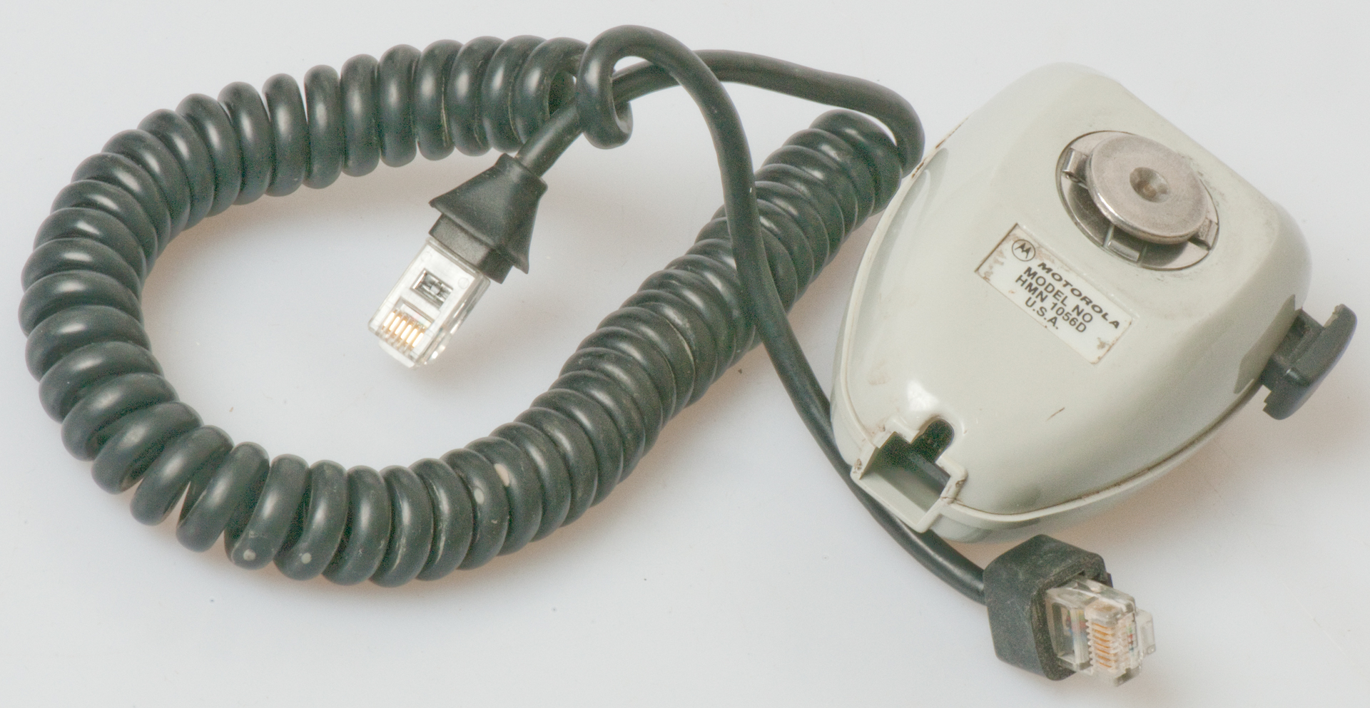 |
Fig 5 Ohming out the cable 8P8C - 6P6C Using Keystone Jacks to make it easier to test cable. |
The Motorola mike did not work out because the wiring is complex.
D-104
After upgrading to the Heil HC5.1 dynamic element I'd like to use this mike, but will need a blocking capacitor to (1) keep from overloading the DC mike drive circuit in the 706 and keep DC from effecting the magnetic properties of the dynamic element.
PC-ALE Project by Charles Brain
US Army Military Affiliate Radio System HF Automatic Link Establishment Information Site - based on the Brian program
ALE Automatic Link Establishment (MIL-STD-188-141; FED-STD-1045) - Details on the 8 tones and their meaning and timing
WUN - Digital Signals FAQ V5.3 - Digital Sounds - ALE -
This is a desk top HF & 6 meter transceiver using digital technology.
Rx range: 30 kHz to 74.8 MHz
Tx range: 160, 80, 40, 30, 20, 17, 15, 12, 10 & 6 meters.
DC Power: 12 Volts <= 21 Amps
Radio Analog makes the PTRX-7300 Pan Adapter. The stock 7300 can display a span of 1 MHz, the PTRX-7300 has two connection methods: _____ & _____.
YouTube: Unlocking Undocumented Features in the Icom IC-7300, 27:52 - about version programming.
@04:40: Versions: 01=Jap, 02=USA, 03=EUR, 05=ITR, 06=ESP, 07=TPE, 08=KOR, 12=EXPortYouTube: Icom IC-7300 EXPORT Version?, 15:21 - SMT diodes: Digi-Key gen purp 100V 200ma SOD523
@09:05 Japanese version (BC: maybe I can program band edges to match my technician license?)
@16:04 Inside Top & Bottom (diode matrix) - no 70 MHz components in Jap version.
@19:32 Removed top center (KANA) diode - changes default language to English
@21:45 Internal Reset Button
@22:15 Removed second center (EMER) diode - The emergency frequency is no longer available, band edges still Jap, no 60m
@25:34 - When installed the function shown is active.
/ means remove to get function
all diodes installed with cathode end to the right?
TXGEN1
(mars/cap)
D422
KANA
D423
?
D424
?
D419
EMER
D420
?
D421
RXGEN1
D416
TX73M
D417
?
D418
Export
D413
?
D414
?
D415
?
D410
?
D411
?
D412
?
D407
?
D408
?
D409
(Export)
D404
/TX5M
D405
?
D406
?
D401
?
D402
?
D403
4xR
After diode change: Menu - Tools - Others - Reset - All Reset - Next - Yes (Causes reboot)
Icom 7300: How To Set PILEUP BUSTING Audio, 7:45Still Jap band edges.
D
D
D
D
D
Dx
D
D
D
4xR
D
D
@5:26 Mistake, wrong diode config. = US config?
The US and Export versions differ in that D413 is removed for the Export version and D404 is added.
@6:43 With D413 installed. - The export version is a restriction on the US band plan. no 60 m.
@10:29 Mars/Cap: Tx 0.1 to 74.8 MHz
@12:26 After pulling Mars/Cap diode -
@13:40 - NF-A8 PWM 80mm Premium Fan <$20 and much quieter
Ham Radio Coax Entry Panel — KF7P Metalwerks Review, 7:30
KF7P Metal Werks - Entrance Panel Boxes -
K4AX - Icom IC-7300 panadapter waterfall display settings for detail and weak signals, 15:33 - other 7300 related -
Rich Rodgers Online:Icom 7300 Antenna Radiation Pattern Using WSPR Ham Radio shows where you are getting to, 14:04 - WSJT-X for WIN7 - other 7300 related - FT8 -