The PRC-126, PRC-128 and PRC-136 all use the same 816173-821 Frame/Panel Assembly. The label shows up separately in the parts lists so that the F/P can have a common part number.
PRC-126 PRC-128 PRC-128 PRC-136 Frequency (MHz) 30-88 MHz 30 - 88 MHz 130-174 MHz 130-174MHz Freq. Step (kHz) 125 12.5 12.5 12.5 Frame/Panel 816173-821
5820-01-255-5631816173-821
5820-01-255-5631816173-821
5820-01-255-5631816173-821
5820-01-255-5631AF/SYNTH 5820-01-255-5630
815587-821815587-822
5895-01-291-9286
721599-8015895-01-291-9286
721599-8015895-01-291-9286
721599-801RF/IF 5820-01-257-3142
815586-821721597-801 5998-01-288-2255
721598-8015998-01-288-2255
721598-801The 918267-804 Module Cover is also common to the PRC-68A, PRC-68B, PRC-126, PRC-128 and PRC-136.
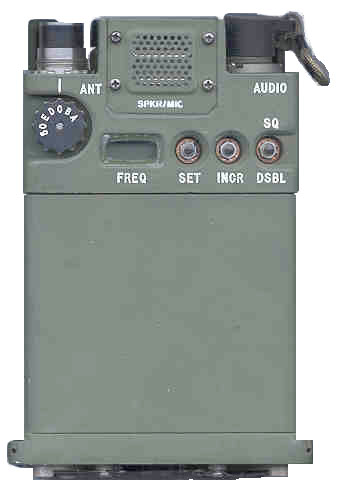
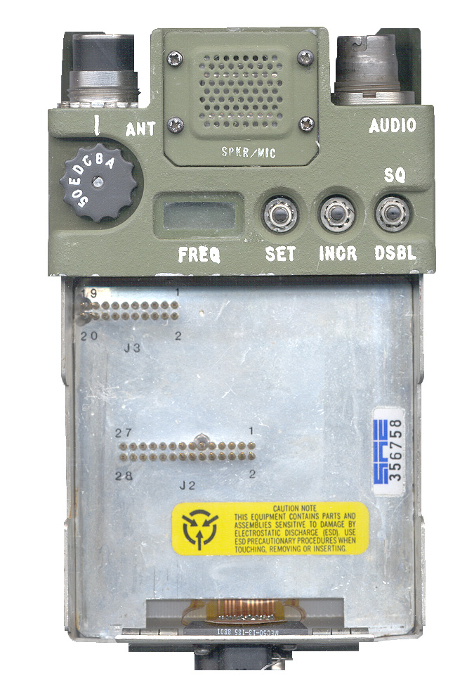
The above photos are of a frame/panel assembly with NO modules installed. If you have a radio that looks like this it is missing both modules.
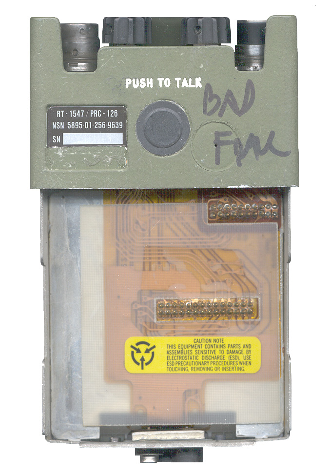
The PRC-126 shown with it's modules removed is marked "BAD FRM" but it appears to be very new and clean.
It passed all the tests on the Frame Simple Tests page, except the SVM jumper plug was missing.
I replaced the SVM jumper plug and it works fine. The radio will not transmit or receive if the jumper plug is not installed.
Schematic Diagram
Back to Brooke's Products for Sale, PRC-68 Radio Family, Squad Radio, Military Information, Electronics, Home, Squad Radio Family Battery Portrait, Squad Radio DC Power Sources, page816173-821 Schematic diagram as 500K byte pdf file. This diagram has colors and line weights to aid in understanding.
For on screen use you can use the pdf magnification feature. Also in a pdf document it's possible to print the current view instead of the whole page so you can print anything you can see on the screen. on line 5 July 2007Frame Simple Tests - separate web page
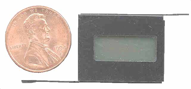
LCD
The first (5,000?) PRC-126 radios used a dark green filter over the LCD to allow Night Vision Goggles to be used with the radio, but you could not read the LCD under daylight conditions. Later versions of the PRC-126 used a clear window over the LCD and the dark green filter was between the LCD and the back light (press and hold SET after the radio has been on for more than 10 seconds). The PRC-128 and PRC-136 also have this Night Vision type back light. In a very dark place you can just see the back light if you look at an angle. Also see PRC-126 Mistake
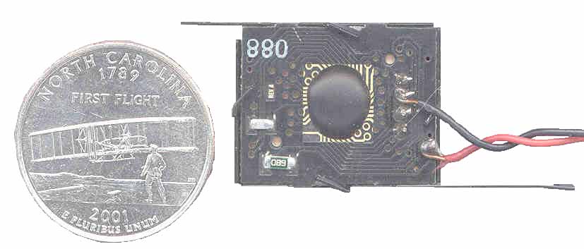
There are 5 digits each about 1/8" high with 7 segments (& dp). There are 5 solder pins. The PRC-68B LCD has only 4 solder pins because it has no back light. The +5, DATA and CLOCK lines go to the same J3 pin numbers on all radios with LCDs.
New Style LCD 4=data = J3-6
3 = Black = ground
2 = clock = J3-10
1 = +5 V = J3-12Old Style LCD
This is the early style that has a bright back light and a filter on top of the LCD discontinued because you could not see the LCd in daylight.
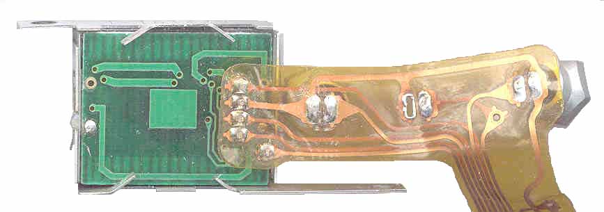
Flex & 3 buttons attached
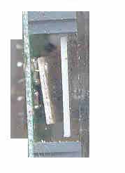
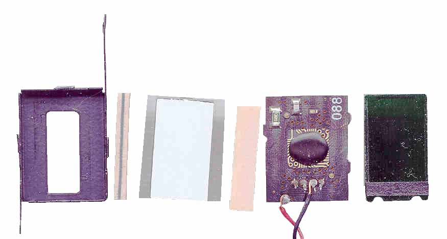
Edge view of Old Style LCD from left: components on fiberglass PCB, angled PCB has green LEDs for back light, white bar is diffuser on back of LCD, top and bottom are the contact strips and glass on right,
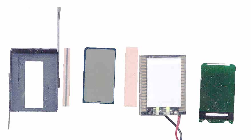
no filter in this assembly, green filter was mounted on radio panel.The center (it's the one with Chip On Board (COB) construction) LCD exploded is shown above.
It has a very dark green filter between the 2 green LED back lights and the LCD. That's why the LCD on late model PRC-126 radios is very dim. By moving the Dark Green filter from the front to behind the LCD both daylight and NVG viewing are possible. You can see the two green LEDs are turned on. Left to right: metal housing, LCD contact strip showing the black conductive "fingers" in the center of the sandwich, the LCD, the other contact strip on it's side, the driver PCB with the back light in the center (the white square) and the two LCDs at the bottom, on the left and right side there are many contacts to drive the LCD, the very dense green filter with a strip of black tape (on thebottom end on the side opposite to the white stripe) that covers the LEDs.If you know who made these or any thing about them let me know.
This is the [an error occurred while processing this directive] time this page has been accessed since 5 July 2001.