Aertech Industries
aka: TRW Microwave
aka: FEI Microwave
© Brooke Clarke 2006 - 2015
Background
Big Picture
Names
Locations & Dates
Products
Tunnel
Diode Based
Tunnel Diode Amplifiers
T5530 Unified S-band
Tunnel
Diode Detectors
Transistor Amplifiers
Detector Log Video Amplifiers
Semiconductors
Diodes
Testing Tunnel Diodes
Limiters
Switches
Schotky Diode
Detectors
Limiter-Detectors
Comb
Generator
Power Dividers
Circulators & Isolators
Sources
Polar Frequency Discriminators
Digital Correlator
Mixers by Bob Mouw
Crystal
Detector
Papers
Related
Links
Background
Aertech was founded by Fred
Schumacher and Harold Harrison in the late 1950s or early
1960s. A couple of their early products were based on the
then newly invented Tunnel Diode (
Wiki).
One was a Tunnel
Diode Detector and the
other was a Tunnel Diode Amplifier. Most of Aertech's
products were in the 1 to 18 GHz frequency range but there were a
few both below and above that range. The two original
product lines were based on
Tunnel Diode
Amplifiers and
Back (tunnel) Diode Detectors.
Note that Tunnel Diodes were then all hand made one at a time and
typically came in "Top Hat" ceramic pill packages.
I worked here from the mid 1960s to the late 1980s.
Big Picture
The Secret History
of Silicon Valley (56 minutes)
Google
Tech Talks, Dec 18 2007 by Steve Blank
Aertech got it's start in Tunnel Diode products by making
components for someone at Stanford who was writing a paper on
them.
Company Names
Aertech was the beginning.
Later bought by TRW (TRW Microwave) in order to get control of the
space qualified Tunnel Diode Amplifiers we were making for them.
Later bought by FEI (FEI Microwave)
Later part sold to ST Microwave and the rest closed down at the
end of the cold war.
The Commercial And Government Entity (CAGE) code stayed 21847.
Metelics was founded by Rudy Dorilag (see
Links
below)) and made products similar to the Aertech line. They
started in an incubator suite at
1031
E. Duane Ave?, Suite _F?_ Sunnyvale and moved to
975
Stewart Drive (just down the street from Aertech/TRW/FEI
Microwave). Later bought out by .Areoflex then Cobham then
MACOM where the Metalics
diodes are lost in a sea of other diodes. Maybe there's a
part number code?
Locations & Dates
When I joined (about 1963) Aertech
was at
250
Polaris in Mountain View.
1967 Aertech moves to
815
Stewart in Sunnyvale (or 825 then 815?)
1968 Aertech at
825
Stewart in Sunnyvale
1984 TRW buys Aertech and even though the FSCM number stays 21847
the name changes to TRW Microwave.
455
Deguigne Dr. was another Aertech Building on the corner of
Thompson Place. Across Thompson was AMD. At the end of
Thompson was a helipad, but it was not used.
1987 FEI buys CAGE code 21847 and the name becomes FEI Microwave
1992 (?) most people are laid off and part of Aertech moves to ST
Microwave.
EPA
Region 9 Super Fund sites - 825 Note that it's very
difficult to tell what building is causing pollution since the
ground water moves it. The only way is to have test wells on
at least 4 sides of a building and compare the upstream
contamination with the down stream, if they are the same then it's
not your building. Driving around the block of Stewart you
can count dozens of test wells Metal caps about half foot in
diameter).
Products
Tunnel Diode Based
The initial products were based on Tunnel Diodes (Wiki) also
called Esaki diodes. They do not store charge (see: How diodes work
& Testing Tunnel Diodes) The
amplifier products which used diodes with peak currents over 1 ma
and detectors which used diodes with peak currents under 1 ma.
Electrical Manufacturing Magazine, February 1960, "The Esaki
"Tunnel" Diode".
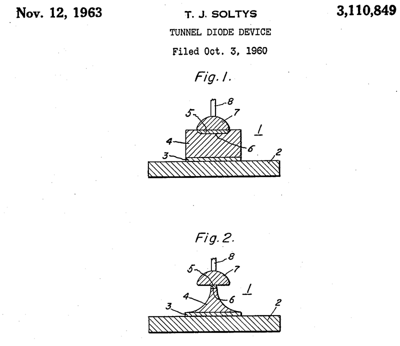
3110849 Tunnel
Diode device, Theodore
J Soltys, Gen
Electric, Nov 12, 1963 - alloy and etch
method i.e. make one at at time by hand, note the "neck (5 &
6) is very fragile.

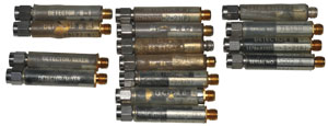
Tunnel Diode Amplifiers
These typically had a lot of tuning screws, see for example the
Aertech TDA on the Wiki
page for Tunnel Diodes. The input has over 10 screws
visible and probably as many on the bottom side. The
output has 5 on the top and I expect there's another 5 on the
bottom. In addition to the screws the center conductor of
that transmission line came in various diameters and by adding
or subtracting spacer blocks you can get other impedance
transformations. In addition you can tune the leg of the
ferrite junction that feeds the amplifier using "U" shaped
dielectrics that get glued into position.
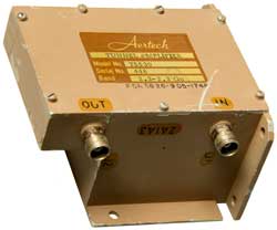
T6654B Tunnel Diode
Amplifier
|
T7670B Tunnel Diode
Amplifier
|
Three Stage T6654B Tunnel
Diode Amplifier Showing Signal Path
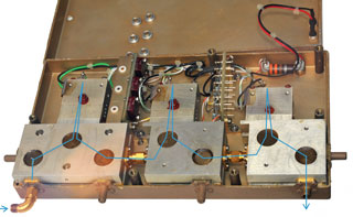
|
Two Stage T7670B Tunnel
Diode Amplifier Inside Showing Signal Path
Notice on the output stage that there are 3 spacer blocks
between the 2
junction circulator and the tunnel diode housing.
They are "tuning" blocks.
The one nearest the circulator has Glyptal on it's tuning
screw.

|
The TD amplifier combines a TD operating in the negative
resistance region with a matching circuit and a circulator to
separate the incident and reflected waves. Since the
isolation of a single junction circulator is around 20 dB the gain
of each stage needs to be less than that to prevent
oscillations.
These amplifiers have two very important properties for space
applications. First the bias voltage and current are both
quite low so the power consumption is also very small. The
Tunnel Diodes are heavily doped and so are not effected by
radiation.
We sold some TDAs that had a built in "D" size Mercury battery and
an on/off switch. One came back many years later because the
battery had run down, but the amplifier worked fine with a new
battery.
TRW acquired Aertech to gain control of the space qualified TD
amplifiers that they were buying from us. We then also built
space qualified hardware on Cost Plus Fixed Fee (CPFF)
contracts. On these contracts it was common to add as much
cost as possible because you got your profit on the total
cost. The means doing things like having your own
Scanning Electron Microscope (SEM) instead of contracting that
out.
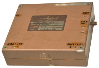
T5530 Unified S-band Tunnel Diode
Amplifier
On the T5530 unified S-band amplifiers I worked on used for
satellite telemetry the bias circuit included a 5.1 Volt Zener
diode. That was because it has near zero temperature
coefficient. The bias circuit also included a position for a
Balco (
Wiki)
positive coefficient resistor and a position for a Veeco negative
coefficient resistor (
Wiki)
was well as some fixed resistors. That way each amplifier
could be customized to have constant gain over a mil-spec
temperature range. This was done using a temperature chamber
with decade resistor boxes connected to the circuit positions for
the Balco and Veeco resistors. A number of amplifiers could
be done in parallel.
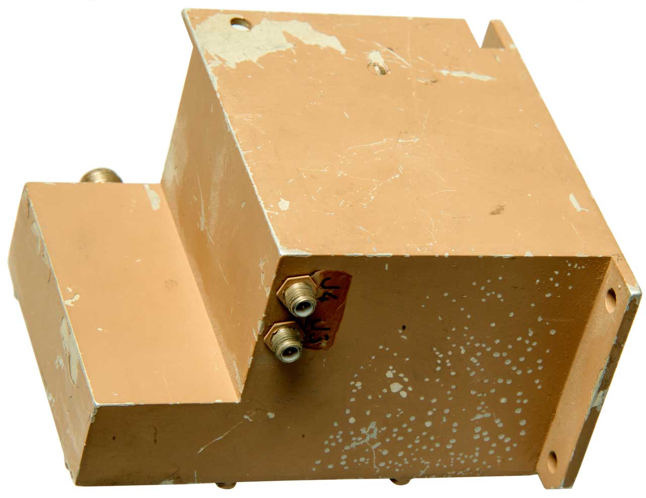
J3
Probably the DC input
J4
700 Ohms - probably the relay coil
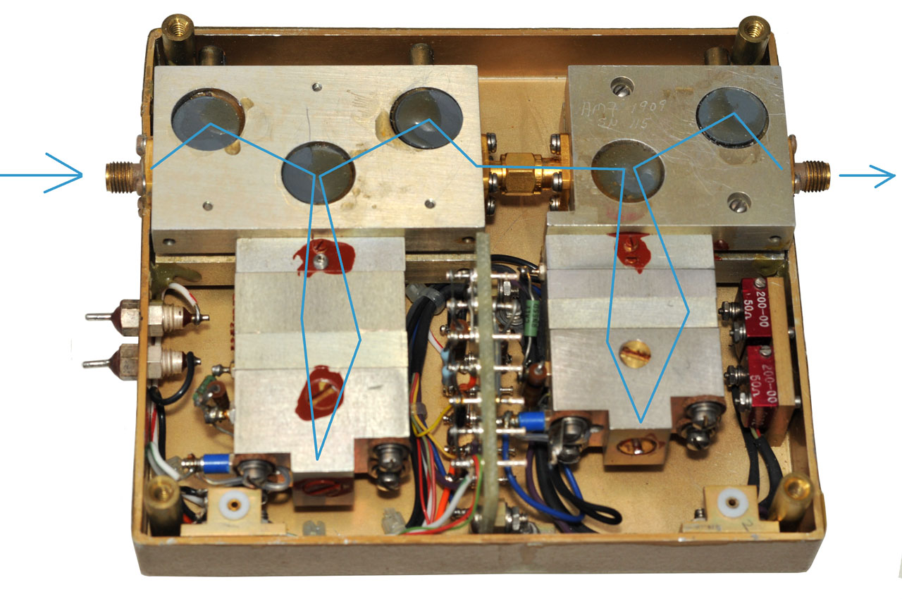
Circulator
When the AMY6 polarity testers is moved around the
top face (label) it shows the relative rotation direction of
that junction:
North near the output
South over the gap between Tunnel and Amplifier
North near the Input
It also had an input so that the bias on the Tunnel Diode could be
set to the valley. In this position the amplifier would act
as an attenuator so large signals could be handled.
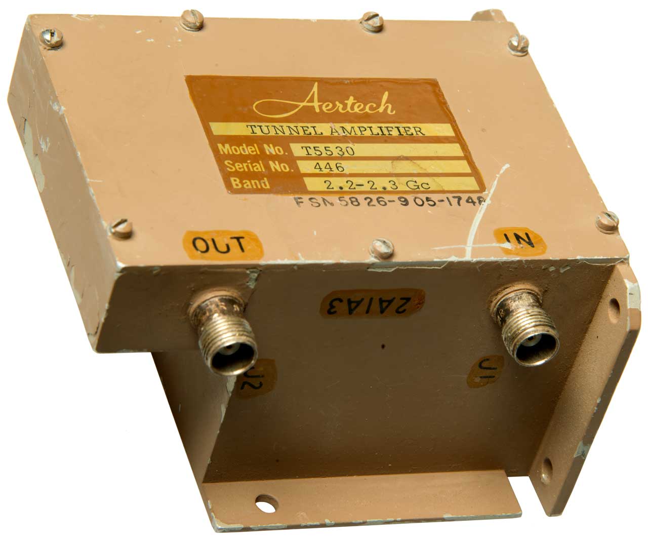
Fig 1 Label:
Aertech
Tunnel Amplifier
Model No. T5530
Serial No. 446
Band: 2.2 - 2.3 Gc
FSN 5826-905-1748
|
Fig 2 J3 & J4: 0.245" dia x 0.21" hi
above hex flange.
one is the DC input the other is
the relay drive for valley voltage bias.
Under the set screw is a gain adjust pot.
 |
|
|
|
|
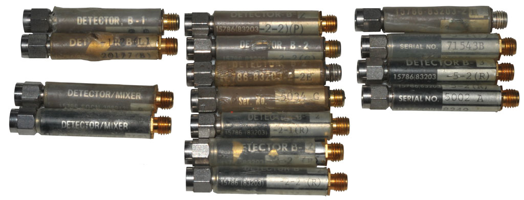
Tunnel Diode Detectors
The Tunnel Diode Detector was one of the first products made at
Aertech.
TD detectors, or more properly
called Back Diode detectors use the diode without any bias.
The diode characteristics are such that the impedance is near 50
Ohms and so is not only a good match to the RF but also to the
video output. This is very important when detecting pulses
since the video bandwidth of the TD detector is much wider than of
a crystal detector. Because of this TD detectors are very
useful in
RADAR countermeasures receivers.
 |
B-1
B-2
B-3
Detector/Mixer
|
Some of the above detectors have bulges and discoloration, so
maybe these came from a dead group.
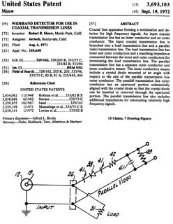
3693103
Wideband Detector for use in Coaxial Transmission Lines, R.B.
Mouw, Sep 19 1972 - replaceable diode (maybe not tunnel diode?)
Detector p/n Prefix Letters
D - Detector
DT - Detector with TNC input
DB - Detector with BNC input
DM - Detector in Miniature configuration (SMA connector input)
DMM - Detector is sub Miniature configuration (SMA connector
input)
DO & DOM Detector 3mm input & output
We used tunnel diode detectors (type-N input) mounted on Narda
couplers as mixers for Noise Measurements. AIL tube type
amplifiers fed the HP 340 NF meter. Mostly used the HP noise
source with a type-N output but sometimes used a hot-cold noise
source that required liquid Nitrogen.
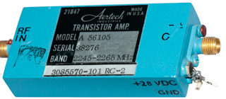
Transistor Amplifiers
There were various types.
The UHF amplifiers were made by Tom Olsen and were lumped
element designs.
The first generation L and S-band telemetry amplifiers were Bob
Mouw designs where the coupling was based on inter-digital
filters. These have excellent out of band
rejection. They are also difficult when it comes to
measuring noise figure since this is a double sideband
measurement with the offset equal to + and - 30MHz. When
measuring near a band edge if one of the sidebands is outside
the filter then the NF appears to be high.
UHF
The VHF - UHF amplifiers made by Tom Olson (
Olsen Technology)
using lumped elements mounted on a solid copper clad fiberglass
board (not etched). The parts were held in place by drilling
a hole though the board and inserting a Teflon standoff (some with
just a post and others that were feed through).
L (1435 - 1540 MHz) & S (2200 - 2300 MHz) Band Telemetry
These amplifiers were made by Bob Mouw. They were
inter-digitated filters at each coupling stage. There is a
huge advantage in that any out of band intermodulation products
are eliminated greatly improving the intercept point and rejecting
out of band signals. Both very important in receiver
preamplifiers. But, this also made it difficult to measure
the noise figure. That because the simple setup we used with
the coupler and TD detector was a double sideband measurement so
that you were measuring the NF at the LO + 30 MHz and the LO - 30
MHz. So if you tested at the specified band edge one of
those would be 30 MHz out of band and because of the steep skirts
on the band pass filters the NF would look bad to a government
inspector that was not microwave savvy.
L and S band telemetry were the two most common applications for
this type of amplifier.
Bob liked to put a lot of tuning screws into his designs.
These had a number of them for each stage so you could "tune it
up".
That means that none of them worked as assembled and all of them
needed a lot of tuning.
|
It's my hope that this is
one of the Bob Mouw design units that has the
interdigitated resonators.
|

|
The holes in the bottom were tapped and used to mount the
various amplifier stages. At the input and output
there were "half filter" sections that just had one
finger. The amplifier stage has one input finger and
one output finger. So based on the hole pattern I'd
say there's an input and output stage on the ends and 4
gain stages between them.
|
Wide Band
These were designed by using S-Parameters after the HP
8410A was introduced. There was a
company that had an automated 8410 system and would test
transistors and supply us with the S-Parameters. The first
generation microwave transistors were Germanium and made by TI.
We built a
transistor tester based
on the GE Transistor Manual and used it to measure the DC
parameters of the transistors and correlated these with the RF
performance. Once that was done it was possible to buy a
batch of the same p/n with the proviso that TI would not have
culled the better transistors. This saved a lot of money
since buying tested transistors was expensive.
Taming the out of band gain was required to prevent oscillations.
Detector Log Video Amplifiers (DLVA)
Final Report for Naval Research Labratory, contract:
N00014-74-C-0020 for two models: 2.6 - 8.0 GHz & 6.9 - 18.0
GHz. DTIC_ADA032880
eBay Serch Term: "(Aertech,TRW,FEI) Detector Log Amplifier"
FEI Microwave LDS 1559
TRW Microwave LDS 1554 8 - 12 GHz
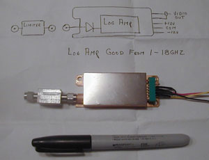
|
This was on eBay " from a multichannel
electronic warfare receiver system that got scrapped"
External limiter is marked: Aertech, A9X712BI
|
Semiconductors
For the first few years all the semiconductors were purchased from
outside vendors and were typically in small cylindrical ceramic
"pill" packages.
Diodes
The first diodes that we made were Tunnel diodes for amplifiers
and back diodes for detectors. This was a manual one at a
time process, i.e. not using wafers or masking. Since Tunnel
diodes are highly doped there is no need for a clean room, i.e. it
was more like a dirty room.
It's difficult to test tunnel diodes because between the voltage
where the peak and valley are located the diode exhibits negative
resistance. In this region the diode will oscillate.
To prevent oscillation the diode needs to see a real resistance
that's lower than it's negative resistance, something that's very
difficult to do over a frequency range that covers DC to 60
GHz. The way we did it was to use a transmission line that
was loaded with lossy material (either cylindrical or a flat plate
transmission lines) and terminated with a fixed resistor. A
bridge circuit can be used to eliminate the fixed resistor from
the measurement allowing the true I-V curve to be seen on a Tek
567 Curve Tracer.
The next stage was to make Schottky diodes for use in detectors
and mixers, then PIN (
Wiki) and
Varactor (
Wiki)
and Step Recovery (
Wiki)
diodes were added. These were made on 2" diameter
wafers which at that time were obsolete for digital ICs and so the
equipment was available at low cost. Since we were dicing
the wafer into chips that were 0.015" x 0.015" the yield per wafer
was on the order of 10,000 chips/wafer there was no motivation to
move to larger wafers. The need for a clean room may
have been the main motivation to move from Mountain View to
Sunnyvale. Sunnyvale was the first city to have a building
code that allowed for both office space and hazardous materials in
the same building (code section H6).
The first clean room was located in the center of the building
with windows. This allowed the exhaust clean air to bleed
into the dirty surrounding space. It also allowed a factory
tour where you could see most of the fab without putting on a
clean suit. A big problem with this arrangement is that you
need to move hazardous material through the office/work
areas. Which is not good if there's a spill.
The same model numbering system was carried over to the diodes.
A1Gnnn - Amplifier Tunnel
A1Ennn - Detector Tunnel
A2xnnn - Schottky
A4Snnn - Step Recovery
A5Snnn - PIN
Testing Tunnel Diodes
I-V
If you put a tunnel diode on a curve tracer it will oscillate
in the part of the curve where there's negative
resistance. Once it starts to oscillate it may
keep going even after the operating point has moved out of the
negative resistance part of the curve. So the diode
needs to be stabilized by shunting it with an impedance that's
lower than the diode negative resistance at all frequencies
below the cutoff frequency. Fco could be in the tens of
GHz so the stabilization circuit needs be based on microwave
design ideas rather than lumped elements.
There were a couple of designs. They were both based on
loaded lines. One was a coax line and the other was
based on slab line, i.e. a couple of Aluminum plates
that sandwiched a block of lossy material.
In both cases a regular carbon resistor was connected in
parallel with the stabilization device.
A special I-V test box connected to any scope. It
included provision to balance out the DC resistance of the
carbon resistor so the I-V plot looked normal.
Capacitance
Calculating Cutoff Frequency
See my
Microwave Diodes web page for
some details on them.
Module Products
These were made using raw semiconductor chips in packages with
hermetic glass to metal seals that had a nominal impedance of 50
Ohms.
This is the product line I developed.
If glass packaged diodes are used
the inductance of the lead wires limits the upper frequency to
below microwave frequencies. This was my first attempt to make a
limiter and it didn't work. In order to work with
microwave signals raw diode chips need to be used.
By placing a couple of fast PIN diodes across a transmission
line you can get a circuit that passes low power levels but that
reflects high power levels. These have an internal DC
return (the A9L100 series).
In order to use raw chips a new packaging technology was
needed. At this time HP had a series of microwave
components that were packaged in a cylindrical package and was
sealed by welding the ends. This was both an expensive and
difficult to use package. I came up with a similar package
which had a protruding lip instead of the recessed shoulder that
was on the HP package making it much easier to integrate into a
final housing. I also used a solder seal instead of the
weld used by HP. This is both lower cost, lower
temperature but also allows repairing a module.
I think Fred and Harold setup a local company to make the glass
to metal seals and to weld them to the central part of the
modules.
A later limiter topology used a shunt PIN diode and an opposite
polarity Schottky diode, with DC blocking caps on each
end. (The A9L200 series)
Switches
A simple microwave switch is just a diode to ground.
When back or zero biased the open diode lets the microwave
signal go past, but when forward biased the diode reflects the
signal keeping it from getting to the output. If the
diode has a short lifetime then the signal interacts with the
bias, like in a limiter where a DC return is provided.
But if a diode with a lifetime that's long compared to the
period of the signal then the signal does not change the bias
and you have a switch.
Wide bandwidth switches require a series diode to isolate the
off output arms. For a microwave switch these need to be
beam lead PIN diodes with very low series capacitance.
Narrow bandwidth switches can be made with all shunt PIN
diodes by spacing the first shunt diode a 1/4 wavelength from
the common junction.
Making a bias-T network that appears as an open over the full
0.1 to 18,000 MHz frequency range is far from trivial.
HP had some of these bias tees.
Schottky Diode Detectors
A Schottky diode (Wiki)
detector needs to have a DC bias applied to get the diode
impedance down to the design value which may be a few hundred
Ohms. A matching circuit is used to get a good VSWR in a
50 Ohm circuit.
The module type (where a raw Schottky diode is used) are the
A9D--- part numbers.
The most common circuit consists of a microwave input matching
circuit which may have the diode mounted at the far end with a
stitched bonding wide to a bypass cap and on to the
output. The polarity can be reversed by mounting the diode
on the output bypass capacitor. The inductance of the
bonding wire between the matching circuit and output capacitor
is very important and so often was not a wire but rather a gold
mesh and that was hand cut from a sheet and typically contained
an odd number of strands so that the center strand could be
bonded to the diode junction thus keeping the mesh on the
centerline of the cylindrical module.
Limiter-Detectors
This was a logical outgrowth of having both limiters and
detectors in the cylindrical package. The first ones were
made by putting a limiter module and a detector module into a
long cylindrical package. The production units were made
using a single long module.
Also see:
Radar Warning Receivers
AM-6536 / ALR-54 Radar Warning Receiver
Front-end
Comb Generator
This was a cylindrical module containing a matching circuit to a
step recovery diode (Wiki).
Model numbers look like A9G100BR. Similar to the HP
33005A/B module, but easier mechanical integration.
The input was something like a half watt signal at 100 MHz and
the output would be a series of signals every 100 MHz, i.e. 100,
200, 300, 400, . . . . MHz.
Hence the name "Comb" generator because that's what it looked
like on a spectrum analyzer.
Some HP spectrum analyzers have one of these built-in to provide
a test signal at many frequencies.
Another way to use these is to use a filter (sometimes a tuned
YIG filter) to select a specific frequency and use that
frequency with a mixer to generate a new frequency or in a
microwave counter, like the EIP counters.
A very special comb generator was used in the HP Large Signal
Network Analyzer (Non Linear network analyzer) as
a calibration test signal.
6812714
Apparatus
for collecting signal measurement data at signal ports of an
RF and microwave device-under-test, under different
impedance load conditions, Agilent
See my Diodes web page under SRD
for more information.
The HP 8406 is a bench top
instrument that's a comb generator.
HP App
Note 920 - Harmonic Generation Using Step Recovery
Diodes and SRD Modules
HP
Components for Control and Conversion of RF and Microwave
Signals 1973 - 1974 - pdf page 16 SRD Modules
HP
Diode & Transistor Designers Catalog 1980 -
3401355
Step recovery diode frequency multiplier, Peter
H Kafitz, Ryan
Aeronautical, 1968-09-10, - Contains tank circuit so
maybe only a single frequency output. Can be used in
phased array RADAR.
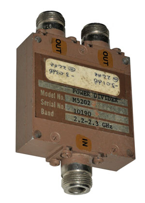
Power Dividers
These were Wilkinson type (1/4 wave lines) (
Wiki)
and were narrow band. The main frequency range was 2.2 - 2.3
GHz to support the then new unified S-band telemetry (
Wiki,
NASA:
Apollo
Unified S-Band Tech Conf NASA SP-87.pdf 1965). There
were a number of designs with 2, 4 or 8 outputs and with various
connectors like SMA, TNC, Type-N.
There is a resistor across the output ports that's located a
quarter wave from the "Y" junction. If a signal is fed into
OUT1 and IN is terminated with 50 Ohms then the resistor is across
a half wave path and so OUT2 sees isolation. For a signal
fed into IN the resistor is at the same potential on the OUT1 and
OUT2 paths and so contributes no loss, i.e. the insertion loss
would be a fraction of a dB higher than 3 dB.
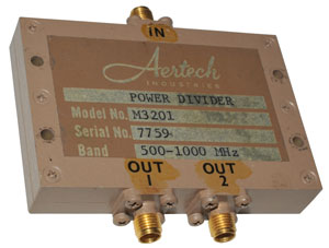 |
|
M3201
Power Divider
500 to 1000 MHz
|
M5202
Power Divider
2.2 to 2.3 GHz (S-band telemetry)
|
Circulators (Wiki)
& Isolators (Wiki)
At some point the design and manufacture of circulators and
isolators was brought in house. Prior to that an outside
captive company made the circulators and isolators used in the
Tunnel Diode Amplifiers. The electrical specs are very
tightly coupled. For example if you tune the unit for very
good return loss at some frequency the isolation will be very good
at that frequency and to a lesser extent so will the insertion
loss.
Note: A circulator has 3 connectors and an isolator has 2
connectors and a built-in termination.
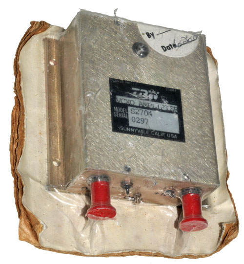
Sources
Don't remember much about these. Found unit on eBay.
Marked VCXO Amplifier
Model: S2704
Serial: 0297
QA Stamp date: 6-26-84
Connectors (left to right): RF OUT (SMAf), -12V, Gnd, +15V, V
T
(SMAf)
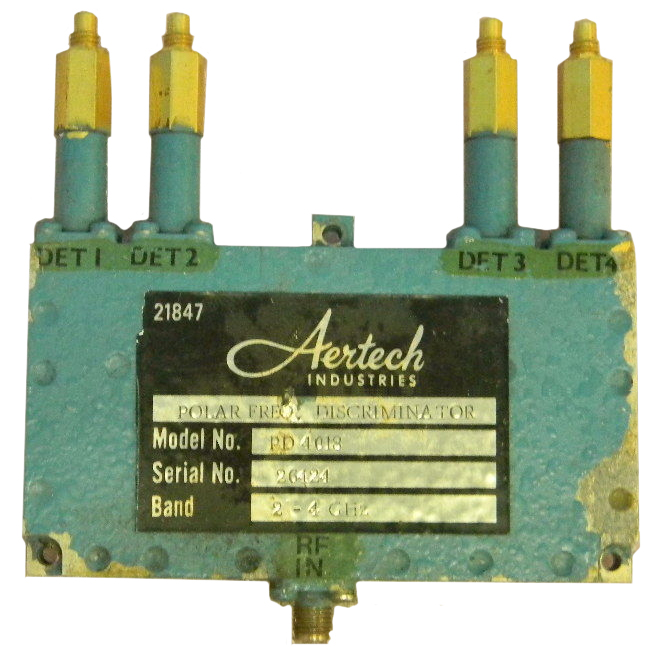
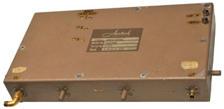
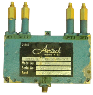
Polar Frequency Discriminators (aka
Instantaneous Frequency Monitor)
|
2 to 4 GHz input at bottom center.
Output DC coupled signals on the 4 detectors.
If all the detectors have zero to positive outputs (or
zero to negative outputs) then the X pair and the Y pair
will go into differential inputs so that the combined X
(and combined Y) channels will be bipolar. That way
when fed into the X and Y inputs to an oscilloscope you
will see a circle when a sweep from 2 to 4 GHz is the
input. The radius of the circle is the power and the
angle of the spot is the frequency. In the actual
system the differential amps would feed very fast A/D
converters.
|
These were strip-line components that typically had four microwave
detectors as the outputs. A number of them could be cascaded
where the delay line length causes them to work like a gas meter
so each added unit provided finer resolution. They worked
great on pulsed signals, but had a problem with CW signals.
Bill Rocko (spelling?) developed the product line. He also
was expert in making scale models where the dielectric constant
also needs to be scaled.
3015776 Indicating fluctuations in
frequency and amplitude, Feb 9, 1957
- used with phonograph records
3061780
Polar
displayer, Jr
Chester B Watts, Alford
Andrew, Mar 19, 1956
3083336 Direct reading, 360 degree phase meter, Poirier
Jules Hubert, Ryan
Aeronautical Co, Jul 12, 1960,
3135917
Frequency
sensitive wave analyzer including frequency sensing phase
shifting means, Ethridge
C Best, Martin
R Richmond, Sanders
Associates Inc, Sep 11, 1961
3395346 Phase and instantaneous
frequency discriminator,
Kincheloe
William R, Wilkens
Mark W, Research
Corp, Mar 24, 1965,
3517309
Microwave signal processing apparatus,
Carl W Gerst,
ANAREN MICROWAVE Inc,
1970-06-23 - This is the basic idea, 4 channels drive a scope.
Calls:
3423688
Hybrid-coupled amplifier, Harold Seidel, Bell Labs, 1969-01-21
3444475
Broadband hybrid-coupled circuit, Harold Seidel, Bell Labs,
1969-05-13
3518541
Digital Phase Measuring Set, Jun 1970
3568067
Frequency Discriminator with Output Indicitive of Difference
Between Input and Local Reference Signals, Collins, Mar 1971
3956706 Miniaturized
millimeter wave instantaneous frequency discriminator, David
L. Saul, US
Navy, May 11, 1976
4144491
Frequency measuring apparatus, Raytheon, Mar 13, 1979
4414505
Microwave instantaneous frequency measurement apparatus, Nov 8,
1983
Digital Correlator
There was a guy from the UK, his name might be Williams, and he
described a way to measure the impulse response of a steam
generating plant. Note that sending an impulse into a
steam turbine would destroy it, so his system using a piston to
increase or decrease the steam pressure by a small amount and
then correlating the input with the electrical output results in
the impulse response for the whole plant.
3718813
Technique for correlation method of determining system impulse
response, O Williams, J Peatman, 1973-02-27 -
Mixers
Bob Mouw was the first person to
make a double balanced mixer that worked at microwave
frequencies. Prior to his invention double balanced mixers
were made using a couple of ferrite balun transformers and a
"ring" connected diode quad. Their upper frequency limit was
around 2 GHz. Bob took the classical circuit and made a
"dual" that used a "star" diode quad and hybrid coaxial
transmission line transformers. I helped do the mathematical
analysis for this mixer. You can consider the diodes as
switches that are turned on and off by the Local Oscillator.
The two states either pass the input signal or invert the input
signal. Doing an FFT on the waveform gives all the frequency
domain outputs of a mixer, less those that are cancelled due to
the mixer balance.
The ides is to make the dual circuit of the ring double balanced
mixer.
The mixer equation is:
IF = +/- m * RF +/- n * LO
given a desired RF frequency and an LO frequency there are many IF
frequencies generated.
Orin Gobby (spelling?) was a expert when it came to receiver
design. Choosing the LO frequency to minimize spurious
signals is as much an art as a science. You can make a plot
of LO, RF and IF frequencies all normalized and they choose the LO
and IF frequencies in order to get the desired spur free frequency
range.
Semiconductor mixer performance has a limit to how large a signal
can be handled. WJ wrote some app notes trying to get at the
cause. The answer can be found on my
microwave
diodes web page.
"Broadband Double Balanced Mixer/Modulators" by R.
B. Mouw and S. M.
Fukuchi,
published in the Microwave Journal, pages 133-134, March
1969.
Steve Fukuchi worked with bob on the mixer line.
3512090 (
Google)
5 /1970 HYBRID JUNCTIONS AND MIXERS AND MODULATORS CONSTRUCTED
THEREFROM,
Mouw
Robert B
Issued/ Filed: May 12, 1970 / Oct. 18, 1967
455/326;
333/24R; 455/331 - Is the first version of the Mouw mixer
pattern
Note: the coax lines have had their center
conductor heated and pulled out and replaced with a new
centerconductor of smaller diameter
(i.e. the 50 Ohm line is transformed into
a higher impedance line).
3818385 (Google)
Hybrid junction and mixer
or modulator, R.B.
Mouw, Aertech,
Jun 18, 1974,
333/26,
333/243,
455/326,
333/238,
333/35
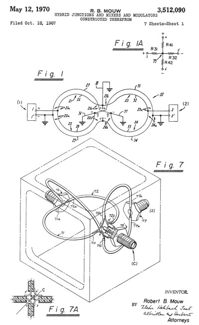
The diodes shown on the first page are in glass
packages. Later there were much more advanced versions
built. These typically were made in octave bandwidths.
3818385
06/18/1974 HYBRID JUNCTION AND MIXER OR MODULATOR
333/26;
333/35; 333/238; 333/243; 455/326
- Mouw-"Broad Band Hybrid Junction & Application to the
Star Modulator" Nov. 68, IEEE-Transactions on Microwave Theory
& Tech. Vol. MTT-16, No. 11.
- "Compensated-Balun;" Oltman, March 66; IEEE-Transactions on
Microwave Theory & Techniques pp. 112-119.
3638126
01/25/1972 HIGH-FREQUENCY CONVERTER - Bob later worked for
Spacek Labs on millimeter
components.
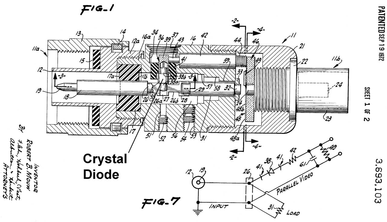
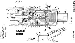
Crystal Detector
Came across another Robert
B. Mouw patent for this detector. Unlike pretty much
all the other detectors made at Aertech, this on uses a
classical crystal (similar to the 1N21
but in a much smaller package). This probably was to offer
an alternate to the common HP 423 type detector in the same form
factor for general lab use, i.e. Type-Nm input and BNCf output.
This may or may not be related to the Tunnel Diode I-V test
system developed at Aertech. It used a transmission line
in parallel with the normal I-V circuitry.
|
 |
3693103
Wideband detector for use in coaxial transmission lines, Robert B Mouw,
Aertech,
1972-09-19, 324/95; 333/125; 333/206 -
Calls:
2454062
High-frequency conductor having a low impedance movable
electrical contact device, UK,
3038086
Radio frequency logic circuits, RCA - have parallel paths
3350655
Electrical crystal unit for use at microwave frequencies,
Theodore
S Saad, GTE
Sylvania, 1967-10-31, -
3559109
Microwave switch, Alcatel,
1971-01-26, - parallel paths
3638141
Compact, high-power, high-efficiency silicon avalanche
diode l-band oscillator, RCA, - parallel paths
What was the model number, D12? Let me know.
|
Papers
Related
Links
Herotec
Inc - founded by Cheng Lai - makes microwave components
Metelics - founded by Rudy
Dorilag - makes microwave semiconductors- there was a problem with
the stock which required
blowing
up the company.
ST
Microwave - acquired some of FEI Microwave when the cold war
ended
Trimetric
Engineering - Mike Butler the first R&D machinist at
Aertech (1964)
There were many other companies that spun out from Aertech/TRW
Microwave/FEI Microwave.
Let me
know their names.
eBay search terms:
(Aertech,TRW,FEI)(Microwave,Ind,Industries) - all inclusive
plus some extra stuff.
Wiki: R
ussian
Tunnel & Back Diodes.
Back to Brooke's Products
for Sale, Home, Rack and Stack Systems, Past Projects page
Page created: 8 Nov 2006.