This is all based on work by Peter Martinez G3PLX.
It was written up in RadCom for June & July 2000.
See: http://www.qsl.net/zl1bpu/chirp/chirps.html for more information.AE4TM HF Propagation Study - PACTOR alows measuring delay time, but this requires another station with known delay times
Hardware
An HF receiver capable of USB mode, IF BW of 3 kHz.
The audio is fed to the left line input of the Motorola DSP56002EVM.
The AGC should be turned off.
A GPS receiver with NMEA RMC data sentence feeding the EVM.
The NMEA data needs to be at TTL levels either through a MAX232 or transistor (these both invert the logic) a diode clamp will not work because it does not do the inversion. Note that the Motorola VP when in NMEA mode will SOMETIMES NOT output the hhmmss time information when in position fix mode, best to use 3D mode to allow the VP to be happy getting fixes and thus enable the hhmmss time stamp.
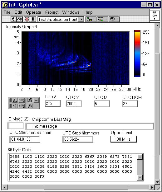
A PC running 32 bit windows and the Chirps program or another program processing the data from the EVM.Software
The PC program takes the time stamp from the 56002DSP and computes the zero frequency start time as:
ChTime = timestamp - 0.1 (kHz/sec) * RcvrFreq (kHz) - 0.0165 ms
The 0.0165 ms is the time to get to the center of the USB band that's 300 Hz to 3000 Hz [cf= (300 + 3000)/2 = 1650]at 100 kHz/sec. This can be used to make the reverse calculation:
Time stamp value = ChTime +10* RcvrFreq(MHz) + 0.0165 secIn operation the PC Chirp program is allowed to run for about 24 hours and the statistics file accumulates those chirps whose periods are defined in the ini file. Optionally a log file can be saved that has all the time stamps.
Note that some digital modulation schemes that sound to your ear like warbling tones cause a couple of dozen bogus chirp time stamps. Also noise hits sometimes cause hits. Some sounders are polite and skip time frequencies like 2.5, 5, 8.3, 10, 13.3, 15, 18, 20 MHz. So if you listen on a time station you may miss a number of sounders. Voice does not typically cause time stamps to occur so you can listen on a station with voice, but the receiver may be desensed.
Receiver Calibration
The time delay through the receiver needs to be known. The DSP box outputs a chirp that can be used to modulate an RF carrier fed to the receiver and the USB audio is feed back to the DSP box. Note that DSP based receivers have a much longer delay than older analog receivers.
Also the time delay may be a function of the IF BW on DSP receivers. Here is the inititalzation file for my NRD-545 with the IF BW at 3.5 kHz, the maximum usable.[evmchirp]
comport=COM1
plxboot=TRUE
gain=0
threshold=15.00
offset=0.991910
name=N6GCE
periods=300,450,480,600,720,900,1800
Vertical Incidence
There are a number of HF ionospheric sounder transmitters operated by different groups for different reasons.
Most research sounders are of the vertical incidence type and are operated by universities for research.
These typically have the transmit antenna near the receive antenna.
See the Digisonde web page for example.
These transmissions are at 100 kHz/sec or 125 kHz/sec with periods of 450 and 720 seconds (7.5 and 12 minutes).Oblique
The U.S. government and many of it's allies operate the BR Communications type of system both as a way of frequency management and to short message transmission. The transmitter is located at one end of a path and the receiver at the other end. These transmissions are mostly at 100 kHz/sec with periods of 300 or 900 seconds (5 or 15 minutes). I know of one at 50 kHz/sec. Some of these have up to a 40 character FSK modulated "order wire" message superimposed on the sweep that is repeated many times.
The period is the time between transmissions and the start time is the theoretical time a sweep starts from 0 MHz.
Note that the start time is always less than the period. The start time is referenced to the top of the hour.
|
|
|
|
|
|
| Vertical sounder | 720:169.02104 - Real | Puerto Rico | N 18 | W 67 |
| 720:198.84155 - Horizontal sounder LPA ant | ||||
| 720:204.01425 - Vertical sounder | 720:318.01420 - Real | Norfolk, VA | N 38 | W 77 |
| 720:377.14959 - Horizontal sounder LPA ant | ||||
| 720:382.02131 - Horizontal sounder LPA ant | ||||
| 720:661.39985 - Horizontal sounder LPA ant | ||||
| 720:666.00963 - Vertical sounder | 720:439.00927 - Real | Kingsville TX | N 28 | W 98 |
It turns out that these are not spurs, but a different colocated sounder using an LPA antenna
Analysis on the 720:204 (Norfolk, VA) sounder
There are 4 chirps very close to each other.
ChT @ 15.8 MHz ChT @ 15.9 MHz Delta Sweep Rate Comment 193.98744 spur 194.20656 0.219128 82.026 kHz/sec 198.62181 spur 198.84175 0.219940 81.97 kHz/sec 199.02200 spur 199.02200 0 100 kHz/sec 4.99241 sec behind 204 204.01441 204.01441 0 100 kHz/sec Real signal Analysis on the 720:666 (Laredo, Mexico) sounder
There are 2 chirps very close to each other
ChT @ 15.8 MHz ChT @ 15.9 MHz Delta Sweep Rate Comment 661.18012 spur 661.39971 81.99 kHz/sec 666.00966 666.00966 0 100 kHz/sec Real signal
G3CWI - Chirp Sounding - HF doppler radar (closley related to chirps)
This is the [an error occurred while processing this directive] time
this page has been accessed since 6 May. 2000.
Back to Brooke's RCS-5, HF
Propagation, Electronics or Home
page