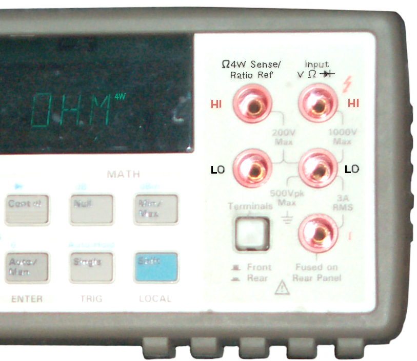
Kelvin Connection Measurements

©Brooke Clarke, 2003 - 2016


Resistance

HP 34401A Input
        TerminalsMany Digital Multimeters, like the Hp/Agilent 34401, have a 4 wire connection for resistance in addition to the two wire connection.  There is a special set of leads for use with the Kelvin connection.  The 34401 reads out to 0.000,1 Ohms.  The 4 wire, Kelvin, connection is very simple.  One of the pairs has a current source and the other pair is a voltmeter.  Suppose that all 4 wires had 10 Ohms of resistance and you want to measure a 1 Ohm resistor using a 1 ma current source. 

If you used a 2 wire Ohm meter then 1 ma * 1 Ohm is 1 mv, but the leads contribute 2 * 10 Ohms * 1 ma = 20 mv of error.   You could try to use the delta DMM function by shorting the leads and pressing zero, but the lead resistance may vary as the leads are moved making it impossible to measure a resistance that's much smaller than the lead resistance.  The contact resistance may also be greater or equal to the resistance of the device you're trying to measure.

For a 4 wire, Kelvin, connection: The resistance in the voltmeter leads has an insignificant effect since the Voltmeter input impedance is 10 Meg Ohms.  Since the meter is connected on the device side of the lead resistance in the current pair that voltage drop is not seen by the voltmeter.  The voltmeter ends up reading 1 mv.  Note that if there is contact resistance and the voltmeter is connected closer to the DUT than the current pair the contact resistance will also be removed from the measurement.  Also note that it really doesn't matter what the lead + contact resistance is, it will be removed from the measurement as long as the current source has the compliance to keep supplying the same current even though the voltage gets large.

By measuring an accurately known resistor using the Kelvin connection you can determine the scale factor (calibration of both the current source and the voltmeter).  This could then be used to improve the overall accuracy of the system.

HP 11059A Kelvin Test Leads

same as Pomona  model 5940 
HP
                11059A Kelvin Test Leads 
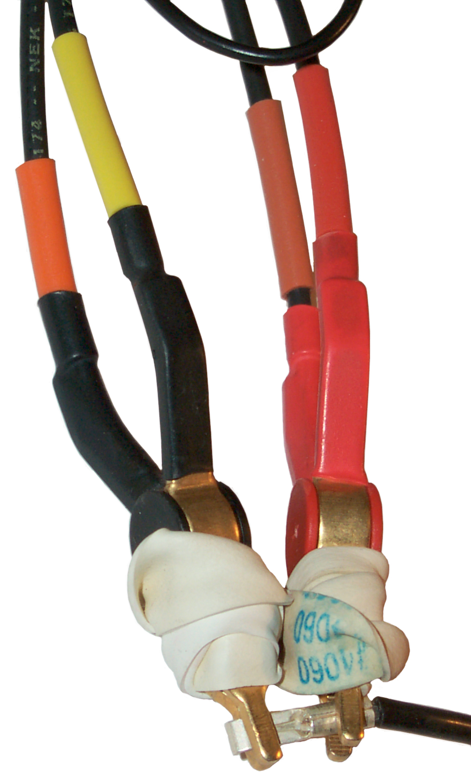
The clips have each jaw insulated from the other jaw and the leads are color coded.  The idea is to use these with the 34401 in 4-Wire Ohms mode and thus be able to measure very small resistances without any contribution of the test leads or the resistance of the connecting joint.
Connection that
                should be zero Ohms


Here a 30 Amp Power Pole Contact (silver plated copper) is being used as the zero reference.    Immediately after making the connection the resistance was 4.5 milli ohms and after an hour was 1.8 milli Ohms.  Although after an hour the variability in the reading is less, it's still a little over 1 milli Ohm.

These leads when combined with the 34401 seem good for may 0.01 Ohms, but not 0.001 Ohms.

The specification is 0.010% of reading + 0.004 Ohms.

The ability of this system to measure very near zero is at the spec limit.  But when larger values are measured it does fine.

There's no need to use NULL for removing the zero since it's in the spec noise.

I checked a pocket Amp meter for which the calculated coil resistance was 2.65 milli Ohms and it measured 2.8 milli Ohms, close enough.
Resistance of
                DMM Test Lead

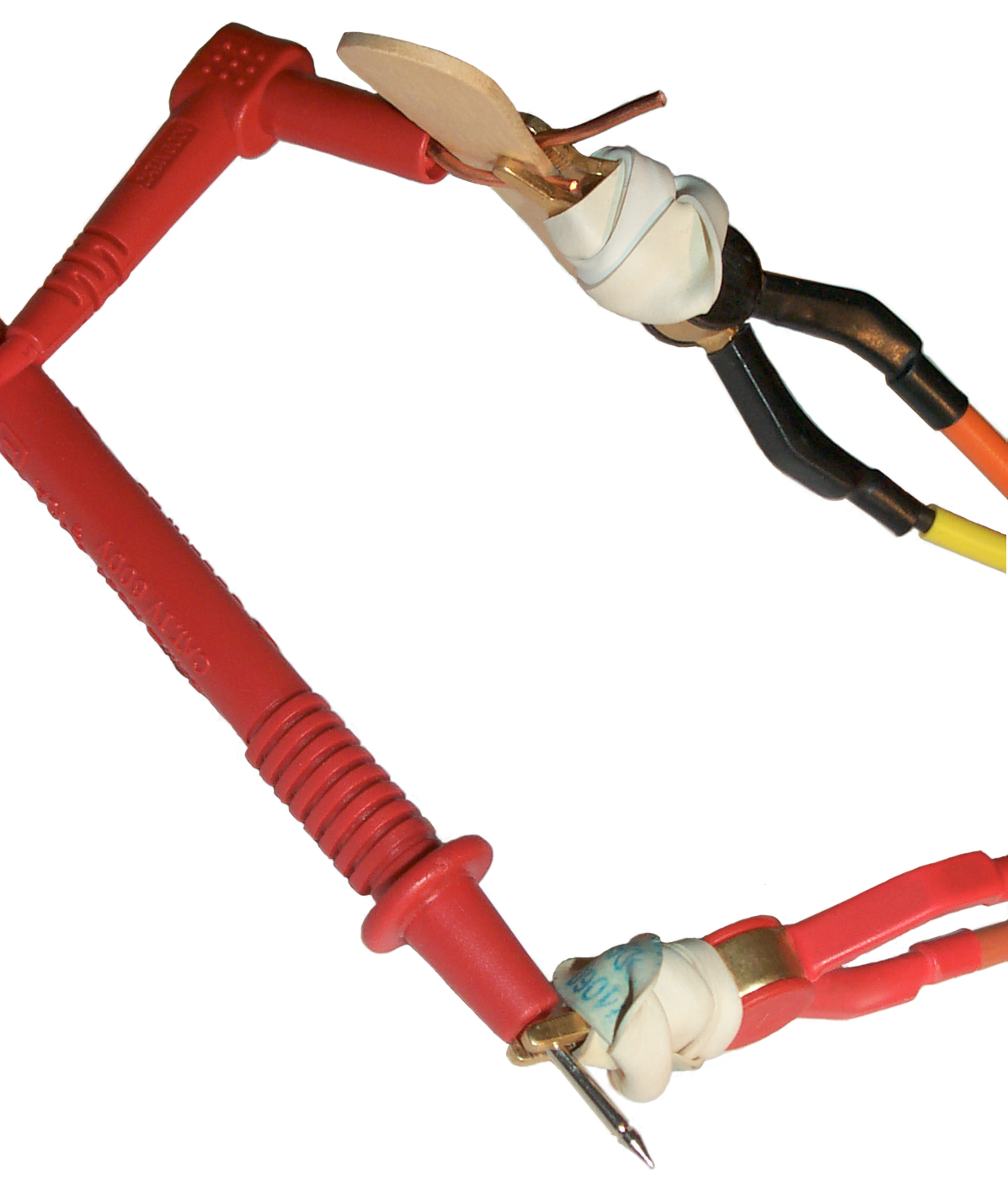
As a sanity check the resistance of a Greenlee test lead from my Fluke 87 DMM was measured.  The problem was the safety shrouded Banana plug.  By sticking a couple of short bare copper 14 AWG wires into the gap between the metal center plug and the metal shell liner and they using a pop-sickle stick to keep the wires from shorting to each other a Kelvin connection was made.

The reading is 0.040.5 Ohms (that's 40 milli Ohms) and has been stable for some time.  It did decrease a few milli Ohms from when first connected but after a few minutes stabilized.
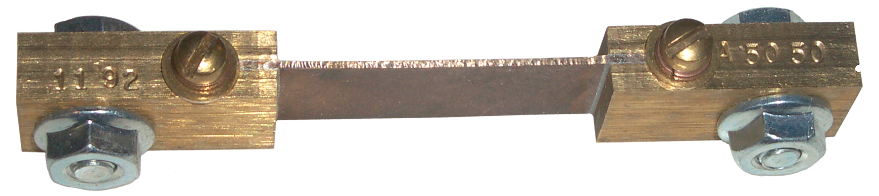

Conclusion

Using low current DC methods, like the 34401 for resistances that are below maybe 50 milli Ohms is not going to work because of thermal effects.  That's why milli Ohm meters like the HP 4328A use an AC method.  The other option is to use a DC current that's large enough that the thermal voltages are very small by comparison.  Maybe 1 Amp instead of 1 milli Amp.

Analog Devices has AN-306 Synchronous System Measures Micro Ohms.  It's based on their AD630 Synchronous Balanced Modulator Demodulator which can pull a signal out of noise that's 100 dB larger.

Current

When measuring the voltage drop across a current shunt it's important how you connect the lugs to the studs on the shunt.

Wrong Way

If the voltmeter leads are installed closer to the source of current then the voltage drop in the high current contact resistance will become part of the measurement making it less accurate.

Correct Way (just an idea, not tested)

Connect the voltage sensing leads close to the shunt and the high current connections further from the shunt.  The idea is that there's some finite resistance between the voltage sense lug and the current supply lug.  By wiring the voltage sense leads close to the shunt those small extra resistances are not part of the measurement.

Current Shunt 50
          mv 50 Amps
This shunt has separate terminals for the high current and the voltage sense and so eliminates the problem of how to connect both to a single post.  The screw is an 8-32 and the bolt is a ¼-20.  For both these sizes there are standard crimp ring tongue terminals.  You can see that here the voltage sensing is done closer to the shunt and the current supply is outside the voltage sensing.

A.C. Test Method

By using an A.C. signal the problems caused by thermal EMFs is eliminated.  This is how the HP 4328A MilliOhmMeter works.  The lowest range is 1 milli Ohm full scale.  It reads 1.0 milli ohms for the shunt shown above.

The same shunt has been on the HP 34401A in MIN-MAX mode for some time and the data is:
MIN:   -37.9 milli ohms   MAX:   +3.66 milli ohms   AVE:   -1.19 milli Ohms   # of Readings:   516,346
Clearly all these measurements are wrong.

Thermopile

Honeywell Q313 A
        1170 Powerpile Generator 750 Millivolt 35" Lead Length
Connecting a Honeywell Powerpile 750 mv Generator with the sensor at room temperature to the HP 34401 in 4-wire Ohms mode gives a reading of +2.6 Ohms, reversing the test leads reads +2.9 Ohms.  But as the thermocouple is heated the apparent resistance climbs and reaches OVLD, i.e. off scale open ckt.  A few minutes after the cigarette lighter has been removed the reading is still 4.2 ohms and it's decreasing slowly.  But the HP 4328A reads 2.9 Ohms with 400 mv DC across the thermocouple (to get 750 mv you need more than a cigarette lighter flame.  There may be 500 u Ohms increase in resistance when it's heated.

Links

Mueller - Kelvin Clips - these are available from most distributors
Pomona Electronics - Kelvin: 5940, 6303 Probe, 6730

Back to Brooke's Products for Sale, General Test Equipment, Microwave Test Equipment, Bateries, Military Information, Home page

page created 12 Aug 2003.