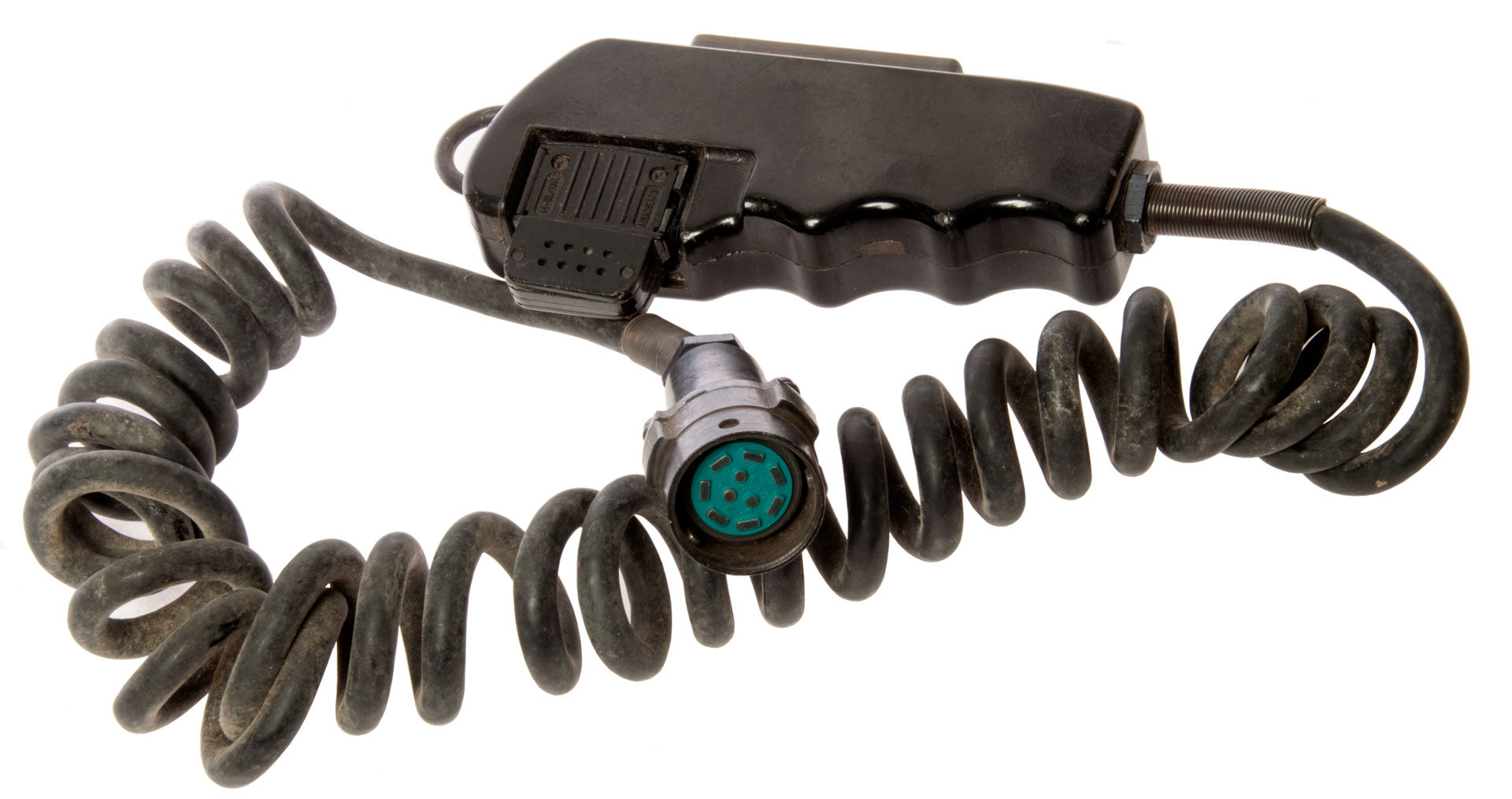
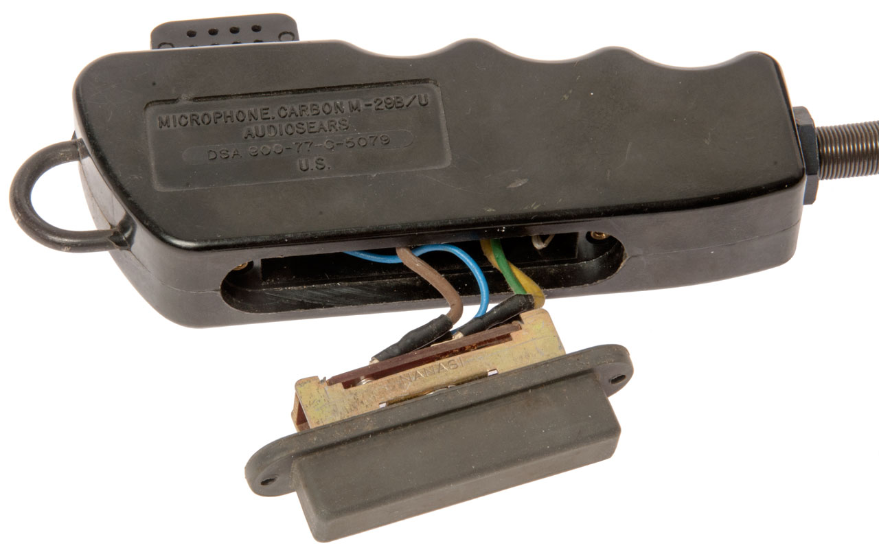
M-29B/U Microphone
© Brooke Clarke 2017
Background
Description
Electrical
U77 Audio Connector
Photos
Patents
Related
References
Links
Background
Description
Electrical
U77 Audio Connector
Photos
Patents
Related
References
Links
Background
This microphone is in the U-77 family the preceeded the current U-229 family of military audio accessories.
The U-77 family all use carbon microphone elements whereas the U-229 family uses dynamic microphone elements.
Description
Main Label:
Microphone Carbon M-29B/U
Audiosears
DSA 800-77-0-5079
U.S.
While this is a hand mike with a Push-To-Talk switch it uses the M-51/UR carbon microphone element.
This element is also used on:
NSN: 5965-295-3966
Microphone: M-52/U
Headset Microphone H-62/U, H-63/U
Aircraft Boom Microphone: M-3/A
Electrical
As received the PTT circuit did not work. Broken Yellow wire at switch terminal was problem. After cutting off the shrink tube the phone tip from the yellow wire was plugged into the socket on the switch. Unplugging the phone tip from the switch allowed cleaning out the yellow insulation, opening the tip wire capture cylinder with a small screw driver and inserting the strands of the stripped yellow wire into the tip, crimping the tip and then soldering. Note this was origionally a crimp only phone tip done through the insulation. Maybe done improperly, or maybe the connection was broken by pulling the conductors back from the tip. Now the PTT circuit is working.
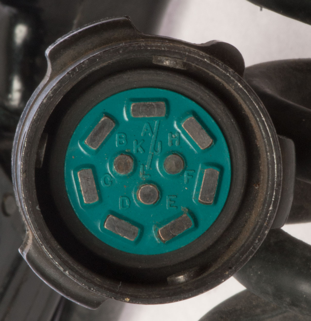
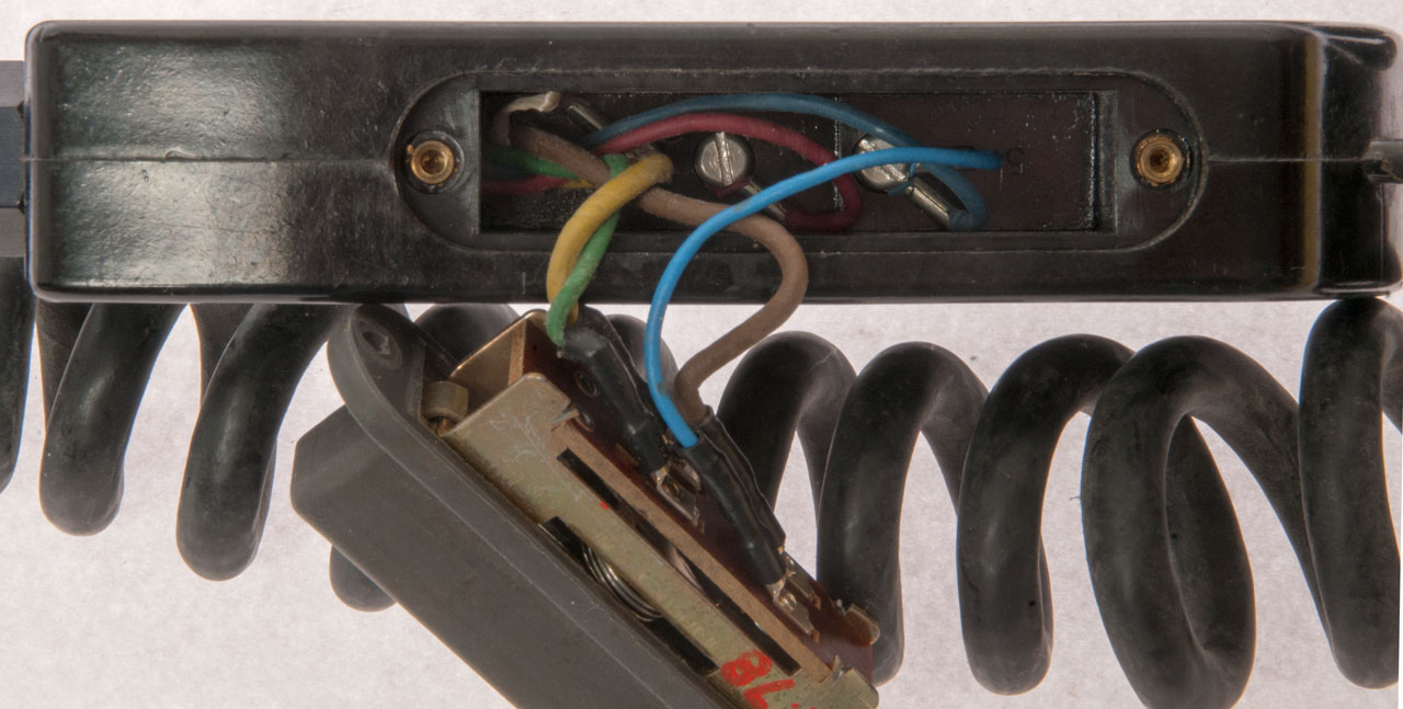
U77 Audio Connector
A - Receiver Audio
B - Receiver Audio Ground
C - Carbon Mike Input (Red)
D - mike ground (Blue)
E - PTT then Mike (Green)
F - isolated Push To Talk (Brown)
H - isolated PTT Ground (Yellow)
J - Remote On-Off
K- CW Key
L - Speaker
Note the U77 connector has provision for either full duplex telephone use by means of microphone pins C & D, or radio use by means of pins C and E where PTT must be pressed for the mike to be active.
Maintenance
Note that the wire colors are much easier to see under LED light.
At U77
C (Red) to D (Blue): 10 k Ohms
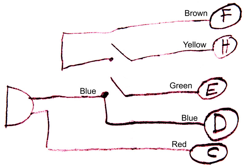
At Switch (Fig 2)
Wiring
Switch: DPST circuit 1: Mike-conn Blue (D) & conn Green (E), circuit 2: conn Brown (F) & conn Yellow (H)
Mike: switch Blue & Mike Blue , Red (C), Conn White (lanyard to coil cord)
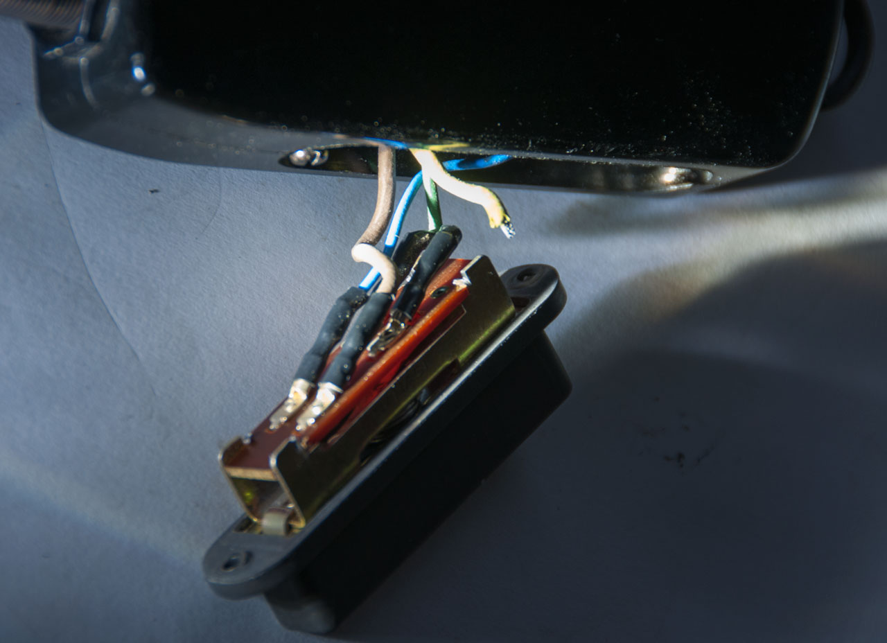
Photos
Fig 1
Fig 2

Fig 3
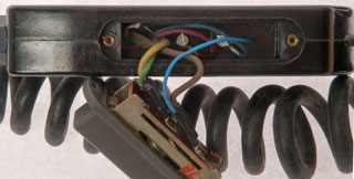
Fig 4
Fig 5 Yellow wire broken at switch (LED light)
Patents
Related
Audio Connectors & Cloning - Fill - Retransmission
Military Audio Accessories - Small Photos
U-229 Audio Accessories - Separate web page
U-229 Pinout by Function - seperate web page
References
Links
PRC68, Alphanumeric Index of Web pages, Contact, Products for Sale
Page Created