When the telegraph system was just
getting going in the early 1800s electromagnets were one of the first
components. At that time they typically consisted of a pair of
coils wound on iron cores. These were used for Sounders and
relays early on. By connecting a pair of coils to an escapement
you could turn the type wheel in a stock ticker quotation machine or
turn the minute hand of a clock.
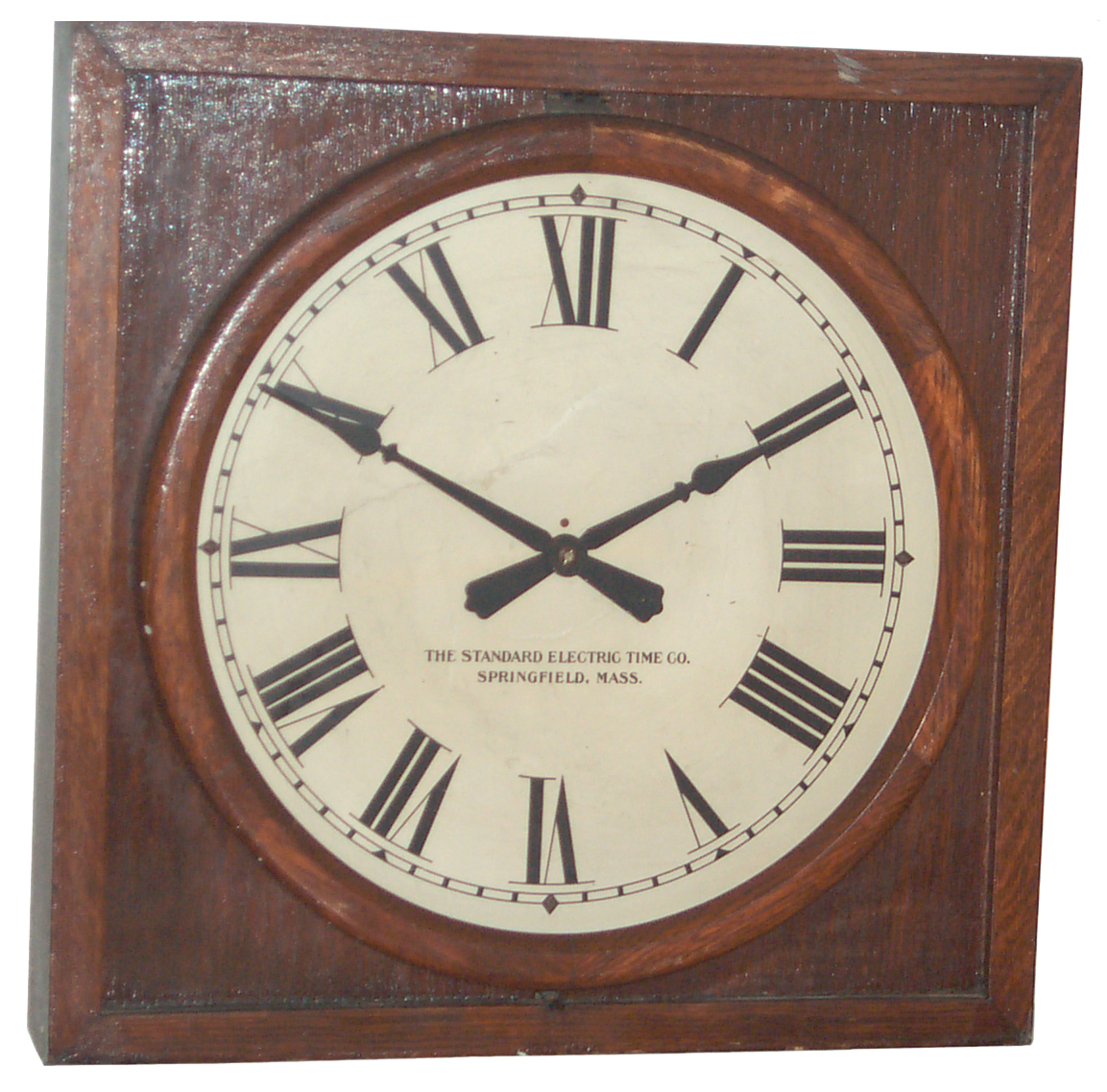
A pendulum clock would act as a master and drive a number of secondary
or slave clocks in public buildings or factories. The Standard
Electric Time Co. was one of a number that made this type of clock.
As received there are a couple of problems.
The spring that moves the minute hand is not strong enough. A
temporary fix is to add some 3"x5" card stock to put more tension on
the spring and this allows the clock to keep time. You can see
the spring in the photo at the left held down by the card stock.
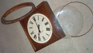
The glass was not tight. It's held in place by a narrow ring of wood, but all the brads have fallen out.
The glass is held in a door that can be hinged up to set the hands
manually but only while the electromagnet's armature is manually
pressed to free the escapement. By using the smallest brads at
the local hardware store and placing them in the existing holes in the
wood (Bamboo?) ring the glass has been reattached. If the
existing holes were not there it would be necessary to drill new
clearance holes since driving a nail into this wood would surly split
it.
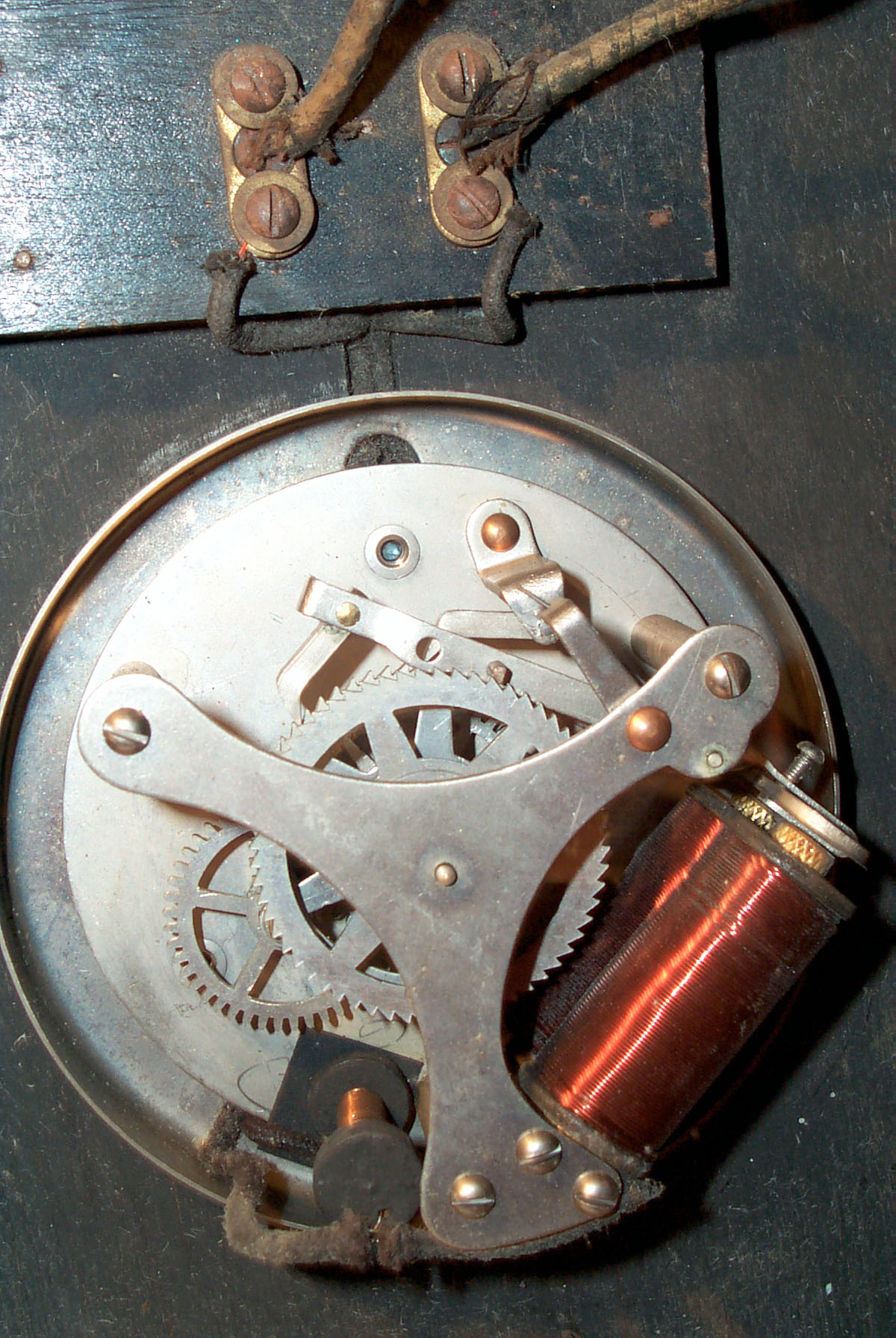
Coil Electrical Properties
Inductance 390 mH, Resistance 10 Ohms,
pull in current 260 ma, drop out current 30 ma. This is with a
small piece of 3x5 card stock adding tension to the spring.
Without adding tension the clock will not move the hands, but with the
card the clock keeps time and the pull in current is about 60 ma and
drop out current is 10 ma.
Coil Calculations
DC
Note that from Ohms Law 10 Ohms times 260 ma is 2.6 volts so you might
expect that clock to operate on a 3 volt power supply and it
will. But if you have a number of clocks all connected in series
then for each added clock another 3 volts will be needed.
Turn On Time
The time constant for a circuit with inductance and resistance is T = L
/ R, so for this clock that's .39 H / 10 Ohms = 0.039 seconods or about
40 ms. It takes about 3 to 5 time constants for the value to
settle so let's say it's in the 0.1 to 0.2 seconds area. Maybe a
little slow, but still much shorter than a minute. The turn on
time can be shortened by placing a resistor in series with the circuit (see
13 May 2007 below).
Turn Off Time with Snubber Diode
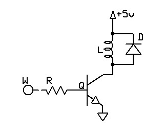
When
the current is stopped the coil generates a voltage spike that's
opposite in polarity from the polarity when the coil was powered.
A common way to protect a transistor that's driving a relay is to place
a diode across the coil with the diode back biased during normal drive
so that when the voltage spike happens it will be shorted out in the
diode. This same method will keep the points in a mechanical
clock from arcing.
This will slow down the time it takes to discharge the coil. The
time constant is the same as calculated above or about 0.1 to 0.2
seconds. So even when these are added toghther they are still
much less than a minute.
For applications like Teletype machines or
Stock Tickers where you need speed the snubber diode can not be used.
Series and Parallel Movements
There are two ways the slave clocks
could be connected, in a Series loop or in Parallel. A major
concern was a way to prevent arcing when the master clock opened the
circuit. This was typically done by a relay for each circuit and
a large building may have dozens of circuits and hundreds of clocks.
The Series connection allows each movement to be tuned then a shunt
resistor wound so as to bring the operating current into the 160 to 180
ma range. Then all the clocks in a circuit have the same current
and so operate reliably AND the shunt resistors act as snubbers to
prevent arcing of the relay points.
The Parallel connected movements don't have the resistor and are
supposed to work reliably from 22 volts (i.e. a 24 V circuit with some
wiring loss.)
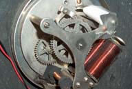
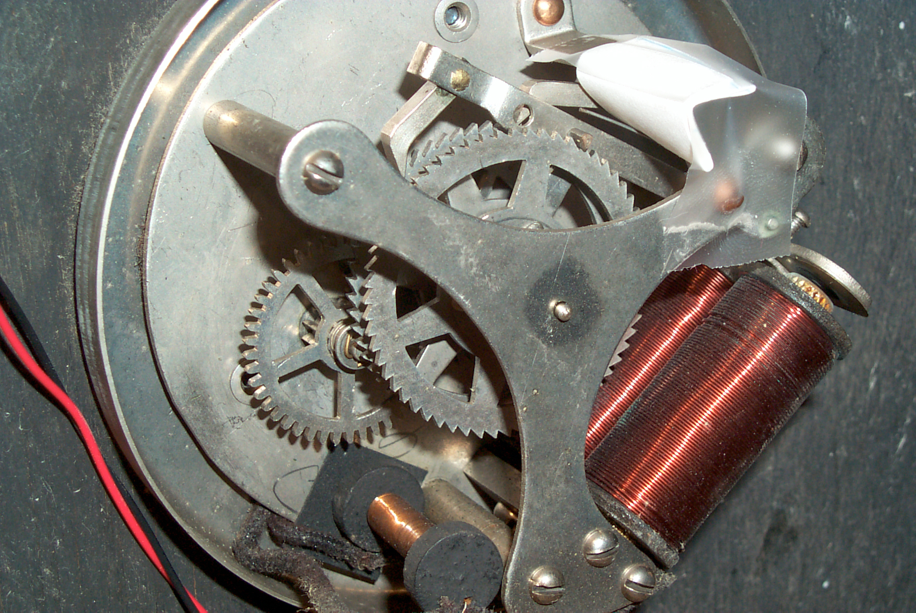
Electro-magnets & Shunt Resistors
As current goes into an electro-magnet
it charges the magnetic field. If the current is stopped the magnetic
field collapses generating a current in the opposite polarity but
starting out at the same value. If there is no snubber circuit across
the coil the voltage can be very high. This causes arcing on the
mechanical points controlling the current input, wearing out the points.
By placing a resistor in parallel with the coil about five to ten times
the
coil resistance the voltage across the coil at the start of the back
EMF will be five to ten times the normal coil voltage and so eliminates
the
point arcing problem. The early shunt resistors were made in the
form of a
coil wound on a non magnetic core where the wire gauge and length
determined the resistance. Note the skinny coil in the above
photos that has it's long axis front to back. Newer versions use
a carbon composition
axial lead resistor.
At first look it appears that there are more more modern snubber
circuits than a plain resistor which dissipates power during coil
charging. For example spark ignition engines use a capacitor across
the distributor points. After the points have been closed for the
dwell time just before they open the capacitor is at zero volts. Just
after the points open the coil back EMF sees the capacitor at zero
volts and so can only generate a voltage across it's own internal
resistance (a very low voltage). Industrial relays use a snubber
circuit consisting of a resistor in series with a capacitor.
But looking further shows there's a second reason why the shunt
resistor was used. It's to prevent a whole string of series connected
clocks from failing if one clock has an open coil. The same idea as
cheap Christmas tree lights.
If this clock has a coil resistance of 110 ohms with a shunt resistor
of 11 ohms yields a combined resistance of 10 ohms. A 24 volt
circuit would have 8 clocks in series and a loop current of 24 V / 80
Ohms or 300 ma. If one coil opened the loop resistance would go
up by 100 ohms or to 180 Ohms and the loop current would fall to 133
ma. Which is still way above the 60 ma needed to operate the
electro-magnet.
Operation
IMP-2 Slave Clock Impulser
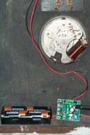
I plan to add a driver stage to my
Precision Clock so that it can drive secondary clocks. But in the mean time I got a
Piexx model
IMP-2 Slave Clock Impulser.
Note:
This Clock Impulser is designed to drive a string of up to 10
clocks. If you are driving only one clock you should place a
resistor in series so that the nominal voltage drop across one clock is
1/10 of the total loop voltage.
I choose the 4 "C" battery holder but they also offer other battery
sizes. This is a cleaver circuit that will drive a number of
different types of slave clocks. It has a built in LM 2733 boost
Switching Mode Power Supply that the micro controller can set for
either 12 or 24 volt outputs. The clock driver circuitry can be
wired for either Uni-polar (like for this clock) or for Bi-polar drive
like used in some European clocks. When the Uni-polar output is
being used for the clock the extra terminal that's not being used can
be connected to an electromagnet that will strike using one of
these:
- Hour Strike
- Hour & half hour strike
- Ships watch strike
- Westminster strike (requires optional board)
- <deactivated>
The rate of the clock can be speeded up or slowed down using the input keys.
To control the IMP-2 there are two input pushbuttons, Set and
Advance. Three status LEDs: Set, Mode and Advance as well as the
impulse LED which also acts as a status LED let you know where you are
in the menu as well as reading back the current vlaues.
In addition to the built in selections for clock type:
- Standard Electric, Stromberg (older)
- IBM (slow type), International
- Gents, other European
- Modern Stromberg
- Manual parameter setting of: Clock Pulse Width, 12 or 24 volt, #
pulses per minute, Uni or Bi Polar, speed up (0.1 sec/day), slow down
(0.1 sec/day), Set minutes for strike, set hour for strike, Chime
style, strike pulse width
- Brille
Experiments
13 May 2007 - The
calculations above based on the electrical measurements show that less
than 3 volts is needed to drive the clock, yet slave clocks of this
type are specified to run in a 24 volt circuit. The reason is
that one circuit can have up to 10 clocks. Remember that for each
battery added to a system there's both the added cost of the battery
and also the added cost of maintenance. So at the time I'm sure
someone worked out a minimal cost number of batteries and it came out
to provide 24 volts. At any rate the clock was designed to be one
of 10 in the loop, so when you drive just one clock in a 24 volt loop a
resistor can be added to make up for the other 9 clocks. 9 clocks
* 24 volts / 10 clocks = 21.6 volts that needs to be dropped.
21.6 volts / 260 ma = 83 Ohms. I used 100 ohms and it's
working. Not only is the clock much quieter but the tick is much
crisper sounding. That's consistent with the faster response time.
14 May 07 - 100 Ohms was too high. The clock was not advancing on
every pulse. Tried 47 ohms and it too may be too high this
morning the clock was 30 minutes slow which probably means missing
pulses. The friction is probably too high at the hub where the
minute hand is a rod inside a sleeve. I've read not to use oil
because it gets gummy in time, but maybe one of the new synthetic oils
would work here? But the minute hand now points smartly to the
line on the dial without the prior slop.
Have used a tiny amount of charcoal lighter fluid wicked between the
minute shaft and the hour sleeve to clean that joint. Now the
minute hand will spin like a top, which it would not before.
I haven't yet received all the literature for this clock. It may
be that I need to disconnect the shunt resistor to allow for more
efficient operation and that's probably quieter and more precise
operation.
19 May 07 - Still something wrong. The minute hand is not
advancing on every pulse. The electromagnet is lifting the pawl,
but it doesn't always move the minute hand. Try increasing the
thickness of 3x5 card stock on the lever spring wire.
25 May 07 - the "Operation and Adjustment of Non-Resetting Minute
Impulse Secondary Clocks (Series or Parallel)" arrived today. And
after going thought the four steps the clock appears to be working, but
I'll know tomorrow. Now it's the one telling the correct time in
the
3 Clocks Photo.
31 May 07 - at 1:08:14 actual time the IMP2 pulsed the SETSC to 1:0:00
pm. So in about 6 days the IMP2 gained 1 min 46 sec or 106
seconds or 17 sec/day. Got lost in the IMP2 menu system.
31 May 07 - 6:00 pm crancked in 7 seconds per day retardation and restarted.
Adjustments
Based on the SET publication "Operation
and Adjustment of Non Resetting Minute
Impulse Secondary Clocks (Series or Parallel)" dated March 1, 1968,
TI-1179 Attn: All Salesmen and Field Service Personnel Available
from
Jeffrey Wood.
1 Adjust or add the Drive Pawl spring.
2 Back Pawl adjustment
3 Drive Pawl Adjustment
4 Drive Lever Spring Tension
After going through the above steps in order the clock is working fine.
Minute Hand
The minute hand is not fixed to the
minute shaft, but is coupled by a clutch (see the patent
above). At first I thought the reason for the clutch was to
allow adjusting the minute hand over a distance less than 1 minute so
that it points to one of the minute dial marks. But now see that
it allows the minute hand to be set anywhere in the hour simply be
lifting the glass and moving the hand manually. When this is done
the hour hand follows the movement of the minute hand. Remember
that the minute shaft is the start of the gear train and is driven by
the electromagnet and locked by the two pawls. When the minute
hand is moved it's connected to the gear that drives the hour hand.
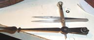
The
minute hand is balanced. The short end has a circular weight
attached by a rivet. In the photo you can see the jeweler's
screwdriver balanced on the tweezers and the minute hand balanced on
the blade of the screwdriver. In the background are the washer
with square center hole and the pin used to hold the minute hand on
it's shaft. Also on the right is the square wood clock box and on
the left the round door since the clock is on it's side.
The slop caused by the location of the two pawls can be minimized by
rotating the fixed pawl stop support arm. But after doing that
I've found that there's additional slop between the minute hand the the
square shaft where they are joined. This was fixed using an
automatic center punch on the back side of the minute hand where it
will not show. The front side was on a hard surface. This
worked the metal a little and closed the gap.
Performance Metrics
1. Position slop of the
minute hand. This clock has slop in the minute hand that's 1 full
minute wide. That's to say you can move the minute hand back and
forth and it covers 1 minute of time. That's way too
sloppy. The movement should be say 10% or less of a minute.
I'm waiting for the instructions before bending the fixed support pawl
arm to tighten up the movement.
2. Power needed to move hands. There now is a
resistor (looks like a coil) that shunts the working coils they wasting
power. This could be disconnected for single clock use. The
shunt resistor is a first generation snubber that absorbes the back EMF
when the coil drive current stops. Without the shunt resistor the
points in the master clock arc and destroy themselves in short order.
3. Pointing accuracy of minute hand. After the slop
is removed the minute hand should point to one of the minute marks on
the dial, not between the marks.
4. Stepping Speed. To determine the minimum power
needed to move the hands the drive current and/or pulse width is
reduced and the clock watched to see if it misses a beat. This
can take a very long time so by running the clock at much higher speeds
the test time can be shortened.
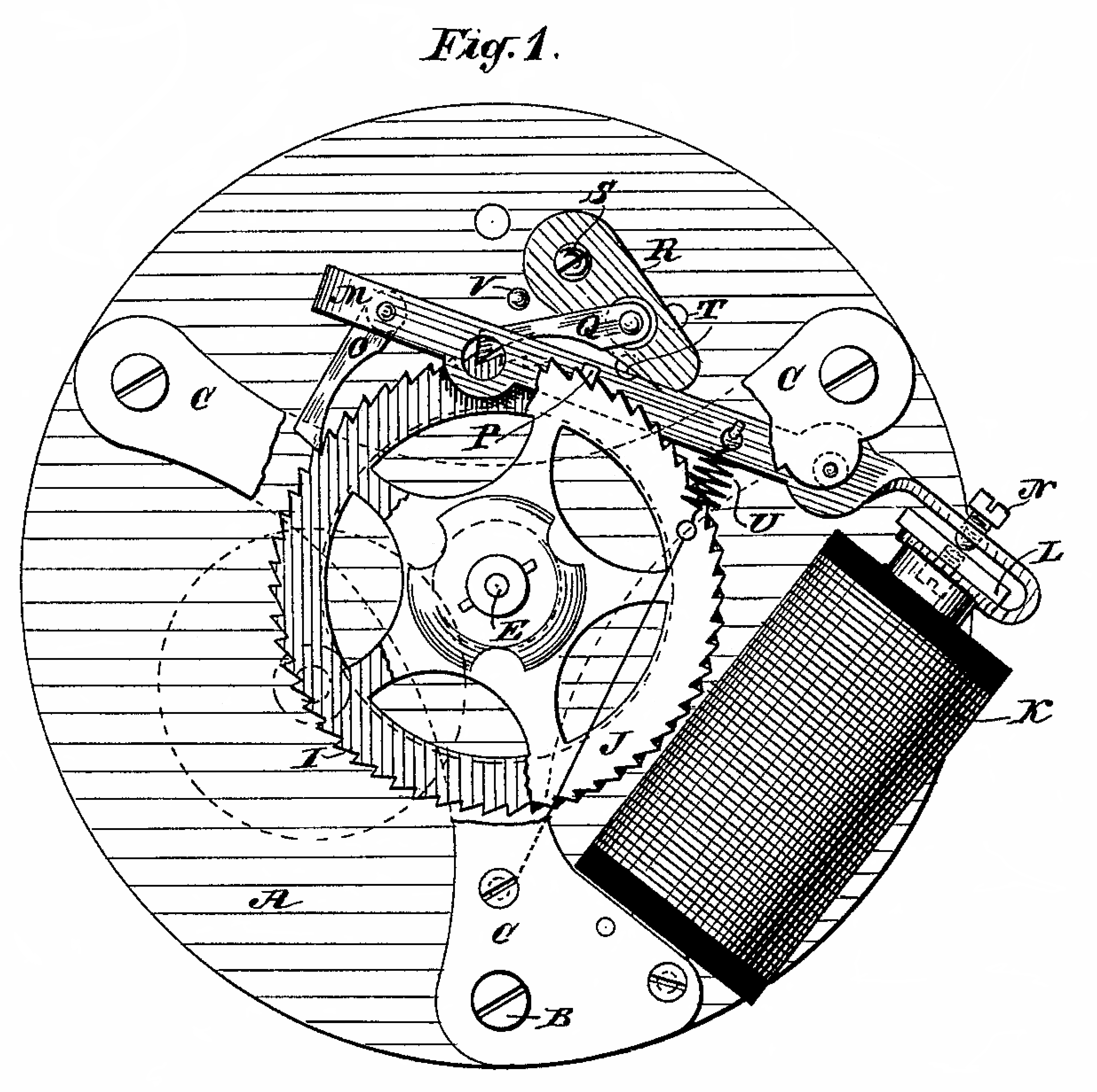
Patents
The key feature of the SET clocks is
the two wheel escapement as set forth in patent 363440. One of
the problems of other escapements is that when there's nearby lighting
the clock minute hand moves due to the induced current spike. The
SET design does not move.
Later patents added hourly setting of both the minute and hour hands
using a number of different methods. The earlier methods were
noisy during the setting process and later methods not so noisy.
The movements that have the hourly setting look very similar to the
above except have a second coil on the left making a "V" arrangement of
coils.
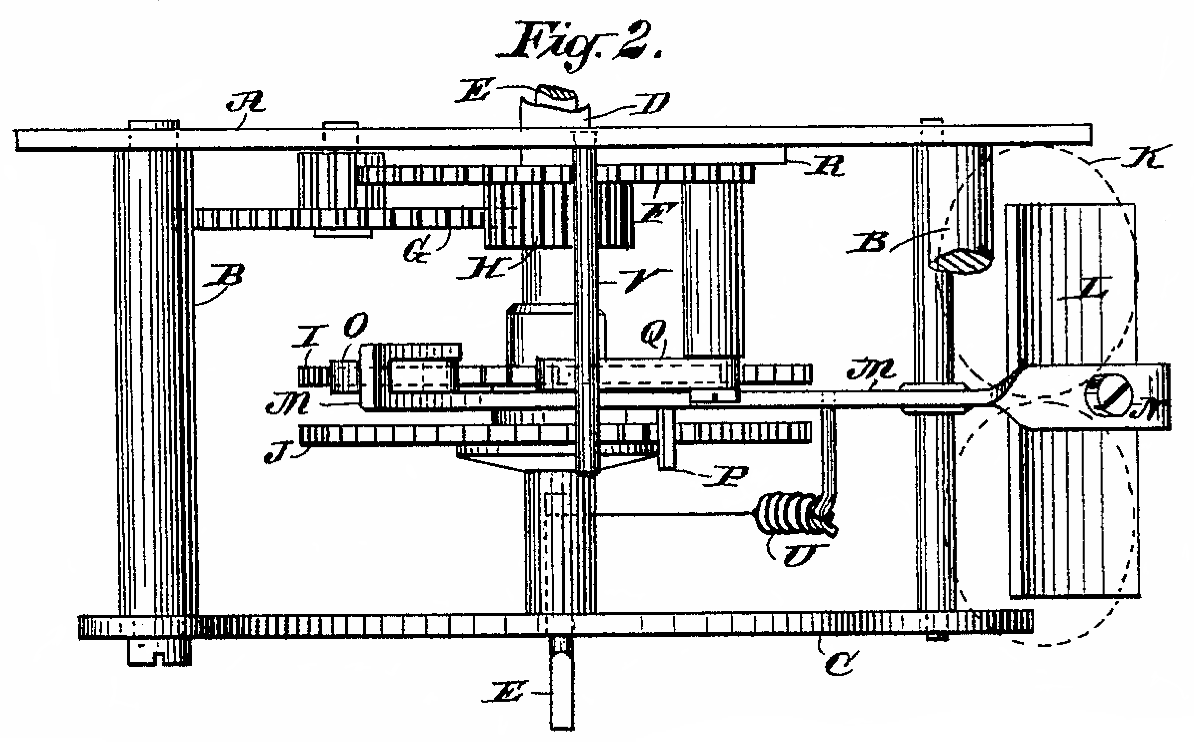
363440 Secondary Electric-Clock Movement, Charles D. Warner, May 24, 1877, 368/59 ; 74/156
- The patent shows item "U" a short fast acting coil spring to
pull down the armature arm, but the actual clock uses a wire spring.
- The patent shows holes "T" near the base of the radius arm base where
it mounts to the back of the dial plate to facilitate rotating the
radius arm about it's single rivet base to adjust the slop in the
minute hand, but the actual clock does not have those holes.
- Patent line numbers 52 to 58 point out how easy it is to make the stop
pawl adjustment by rotating the radius ram about is rivet. Lines
58 to 63 point out that the stop wheel is "movably mounted" to the main
shaft so that it can be adjusted. These two adjustments allow
both minimizing the minute hand slop and getting it to point on an
exact minute boundary dial mark. Although not marked in Fig 2 the
clutch disk that movably holds the stop wheel "J" on the minute hand
shaft "E" is shown.
- "N" on the armature is described as an adjusting screw, but it's purpose is not mentioned.
387703 Circuit-Closer for Electric Clocks,
387704 Electric Clock System, Charles D. Warner &
Arthur D. Bennett (Standard Electric Time Co), August 14, 1888, 368/52
Links
Back to Brooke's Time & Frequency, Personal Home, PRC68 Home
[an error occurred while processing this directive] page created 30 April 2007

 I plan to add a driver stage to my Precision Clock so that it can drive secondary clocks. But in the mean time I got a Piexx model IMP-2 Slave Clock Impulser.
 The
minute hand is balanced. The short end has a circular weight
attached by a rivet. In the photo you can see the jeweler's
screwdriver balanced on the tweezers and the minute hand balanced on
the blade of the screwdriver. In the background are the washer
with square center hole and the pin used to hold the minute hand on
it's shaft. Also on the right is the square wood clock box and on
the left the round door since the clock is on it's side.
The
minute hand is balanced. The short end has a circular weight
attached by a rivet. In the photo you can see the jeweler's
screwdriver balanced on the tweezers and the minute hand balanced on
the blade of the screwdriver. In the background are the washer
with square center hole and the pin used to hold the minute hand on
it's shaft. Also on the right is the square wood clock box and on
the left the round door since the clock is on it's side.