Subscriber Loop Analyzers
© Brooke Clarke 2015 - 2023
Description
Dynatel 745
Operation
Battery
Photos
Dynatel 965
Battery
Photos
Far End Device (FED)
Patents
Related
Links
Background
In the 1950s telephone installers (all working for AT&T) used the KS8455L2 Line Loop Tester aka: Kick Set for testing the phone line while at a subscriber's premises. More modern test sets, like the Tempo Sidekick could make more sophisticated tests, but they required more operator skill. Dynatel came out with a series of subscriber loop analyzers that would automatically run a series of tests on the loop thus lowering the required skill level required of the telephone technician.
Some of these have been showing up on eBay ("Subscriber Loop Analyzer") for very low prices (less than the shipping). I suspect this is because the internal battery has quit taking a charge and needs to be replaced. So it's a gamble buying a Dynatel 745 and Dynatel 965 subscriber loop analyzers in the hope that I can come up with a battery replacement.
Description
Dynatel 745M Subscriber Line Tester (SLT)
At power up the display shows Dynatel 745M, Battery OK (after installing a new battery).
This test set came with test leads and a 2-wire (Red & Black) 1/4" phone plug. I expect the stock test leads would have included a 3-wire (stereo) 1/4" phone plug and Red, Black & Green test wires. How important is the missing green (ground) test wire? Contact me.
Operation
Pressing (Yellow) START/reset powers up the test set. Pressing (Blue) # (when it's not shown on the LCD as an option) turns off the set. This disagrees with the manual that says you need to press # then START to power off. Pressing and holding down START/reset will power down the test set.
Self Test
Once the opening screen is displayed the pressing (Blue) Self Test starts a menu process where pressing (Blue) * selects the test displayed on the top line of the LCD and pressing (Blue) # Other Self-test moves to the next test option. Note that these are not the actual tests but rather calibration or checking of the test set function.
The test options are in order:
Charge Battery
This requires connecting the Red and Black test leads to a source of 12 to 15 VDC. Then the menu sequence:
START/reset, SelfTest, # (Charge Battery), turn SLT upside down for 5 seconds and then right side up.
Leave overnight to charge battery.
After 5 minutes (starting with a charged battery) the SLT makes the power off noise and the LCD turns off. But the power supply is showing 178 mA current draw at 12 Volts. It's not clear if that's going to the battery or just a voltage regulator in the SLT.
If the power supply is disconnected then reconnected the current is zero. So maybe there's a sticky relay that should have turned off?
Ohms Test
Prompts you to short all three (or 2) test leads then does a zero calibration.
Opens Test
Prompts you to remove the 1/4" plug and test leads then does an open calibration.
Dialing Test
Requires connection to an active telephone line to run the test.
Display
By pressing * or # the LCD contrast can be changed for your viewing angle. If the screen goes blank just press the other button (# or *).
Battery
Power sonic PS-610, 6V, 1.0 Amp Hr., 2" x 1.625" x 2.017" hi + 0.187" terminals. When put on a bench power supply (Agilent E3617A) at 65 Volts it initially did not take any current. I'll let it sit overnight with the current limited to 10 mA to see if it's totally dead. A new PS-610 is available on the internet.
After a couple of hours the current is up to about 1 mA. Got new PS-610 battery.
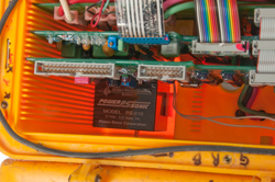
There's a problem when installing battery in that one of the bosses on the bottom of the case interferes with the battery cable end preventing the battery from completely seating. I bent the battery terminal to minimize the problem, but not eliminate it.
After reconnecting everything pressing START/reset causes the LCD to come on and an opening tone to play.
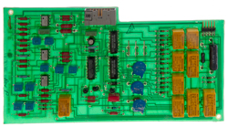
In the lower left of the instructions (Fig 3 below). This involves connecting the red and black test leads to a car battery (12 to 15 VDC source), turning the tester upside down for 5 seconds (see mercury switch on PCB #5 (Fig 10 below) and then righting the tester while battery is on charger.
Note the special battery charging connector next to the 1/4" phone jack is wired to the Red and Black wires on the phone jack, so there's really no need to use it. Just connect the red and black test leads to a 12 to 15 VDC source and go through the menu sequence for battery charging.
745 Photos
Dynatel 965
After replacing the 5 dead Alkaline "C" cells the unit powers up and will do the self calibration, but then "access" is selected (*) the LCD shows:
General Access
Enter Password
What is it? Let me know
Identification
Dynatel 965
0498-9590 965 X
Rev. 2.20 Copr. 1989
SR = 19960916095927
Battery
By unscrewing the 6 captive screws on the bottom panel the 5 "C' cells can be replaced.
The start-up menu allows selecting either Alkaline or Ni-Cad cells.
Like in the 745 above, the Red and Black leads can be used to charge the internal battery (when Ni-Cad "C" cells are installed & selected in the software).
Photos
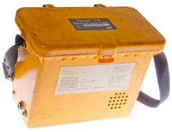
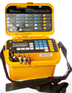
Fig 21 Dynatel 965 Yellow Lunch Box Subscriber Loop Analyzer
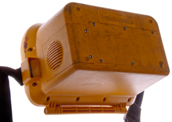
Fig 22 Bottom has compartments.
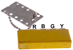
Fig 23 Cable Self Test Circuit
p/n: 0002-7535-001-D 3M
aka: Far End Device (FED)
Fig 24 Battery Compartment
5 Alkaline "C" cells (all tested dead)
Far End Device (FED)
see Fig 23 above.
Attached to the FED is a Dynatel/3M wire gauge.
One side is for 28, 26, 24, 22 & 19 AWG solid copper wire, the other side is for 0.4, 0.5, 0.6, 0.8 & 0.9 mm solid copper wire.
There is an option so select the wire size when doing cable measurements that then recalls the cable parameters for that wire size.
It's not clear how the FED is used.
The 4 test leads on the 965 seem to be Red & Black for a pair and Green & Yellow for another pair. With Green also being used for ground.
Ohm Meter Readings
Red
Blk
Grn
Yel
Red
0
1E6 200
100
Blk
1E6 0
1E6
1E6
Grn
200 1E6 0
100
Yel
100 1E6 100 0
A possible circuit:
(Red) ---100 Ohms ---(Yellow) ---100 Ohms---(Green) ---1 M Ohm---(Black)
Patents
4054759 Subscriber loop verification device and method, Ronald George McGrath, George Howard Wright, Nortel Networks, 1977-10-18, -
4413163 Portable line tester for telecommunication system, Bruno Basini, Leonardo SpA, (Selenia), 1983-11-01, - microcomputer based.
Related
Telephone Equipment - Telephone Patents
Western Electric 202 Dial phone
Bell System 302 Dial Phone
Bell System 500 Dial Phone
Bell system 2500 Touch Tone phone
Western Electric 2554 Wall Touch Tone Telephone
Harris TS1000 ADSL Test Set
Harris TSP-21 Telephone Test Set Plus (like but set, but belt-clip & operators headset
KS8455L2 Line Loop Tester aka: Kick Set
SB-22 Switchboard
SB-4170 Military Telephone Switchboard
EE-8 Army Field Phone
Fuller Phone
TA1 TA-1 Voice Powered Military Field Telephone Set
TA1042 Digital Non-Secure Voice Terminal (DNVT)
TA312 TA-312 Military Field Telephone Set
TA341 TA-341/TT Military Touch Tone Desk Set
TA838 TA-838/TT Military Field Telephone Set
MATEL 2C800 Field Phone by Racal Acoustics Ltd.
Panasonic KX-TA824 Small Business Phone System (PBX)
E-89-A Telephone Repeater
AT&T TSD-3600 Telephone Security Device uses the "Clipper Chip"
TSEK/KY-68 (DSVT Phone)
VOIP Voice Over Internet Protocol
Telegraph
Leclanché Battery - No. 6 Dry Cell
Stock Tickers
Cell Phones
Spying on Cell (Mobil) Phones - Orion Electronics Ltd. Cellular Base Station ST616-CBS (cell phone spy)
LS-147 Intercom
Links
PRC68, Alphanumeric Index of Web pages, Contact, Products for Sale
Page Created 25 May 2015
