Time & Frequency Test Equipment
© Brooke Clarke 2007
TOC
Background
Gibbs Crystal Oscillator
Stanford Research SC10 Crystal Oscillator
Stanford Research PRS10 Disiplined Rubudium Oscillator
HP 53132A Counter
Frequency Standard
Stanford Research SR620 Counter
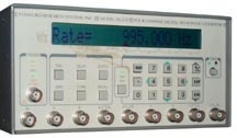
HP 33120A Function ARB Generator
HP 8648A Signal Generator
Stanford Research DG535
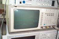
HP 54501 Scope
Links
Background
These are some of the test equipment
I
use for Time & Frequency. Sort of chronological order
oldest
at the top.
The Cesium standards have their own page
FTS4060
Gibbs Crystal Oscillator
Got this for practically nothing
since
it was being sold as a simple crystal oscillator because the oven
was
not working. The problem was that the gel cell lead acid
batteries had vented and the fumes etched away some of the PCB
traces. It's surprising that the
FTS4060
and Datum 4065B both have provision for internal gel cell
batteries! They would suffer that same problem and be
destroyed
if the battery vented. Much better to locate the batteries
external to the main chassis to prevent any acid fumes from
causing
problems.
Stanford Research SC10
Crystal Oscillator
A very versatile design that can be
factory configured to have a control voltage polarity and range to
match about any existing ovenized VCO. Also the crystal
drive can
be adjusted to trade stability and aging. A replacement for
the
Gibbs.
Stanford Research PRS10 Disiplined Rubudium
Oscillator
HP 53132A Counter
I had one of these counters which
can
count something like 12 digits of frequency in 1 second. A
straight cycle counter working with a 10 MHz input would display
10,000,000 after one second, i.e. only 8 digits. But there
are a
couple of things not so good. The manual user interface
might be
called user hostile. The 12 digits does not apply to
measuring
time intervals. Measuring time intervals is what you do when
working with precision frequency or time signals, not measure
frequency
directly. So the 53132 got replaced by the SR620. Note
the
name of the SR620 is not frequency counter, but Time Interval
Counter,
i.e. it was made to do TI counting. The annual conference is
called Precision Time and Time Interval (PTTI).
But (I think, but have not checked it) the TAC32 software is steup
to
work with either this counter or those closly related for making
time
interval measurements aginst GPS and applies the sawtooth
correction,
so they have value for that use.
This is an analog audio generator
who's
frequency can be programmed using a parallel digital
interface.
It was designed with active components added so that reverse
engineering would be more difficult. So far no working,
although
new in the box.
Stanford Research SR620
Universal Time Interval Counter

Currently
measuring
the
difference between a GPS 1 PPS and the output from an
FTS4060/S24 Cesium Standard. The 1 MHz signal from the
Cesium is
the external clock for the counter and it's 1 kHz Reference out is
synchronous with the Cesium input. By using the counter this
way
the time for rollover is improved from 1 micro second to 1 milli
second.
The black triangles are so make it easier to keep straight where
different units are located. The great thing about this
counter
is that there are 15 digits. It does not use exponent
notation,
but rather just puts the digits where they belong. The
current
display is825us 248ns 976ps. This is the result of averaging
100,000 readings which takes a little more than 1 day.
It's
connected to an old computer that's data logging the
readings.
This display turned on at 18:04 on 1 July 2007. On 23 June
at
15:37 the display was 825us 494 ns. So the 4060 frequency is
off
by (825494-825248) / 700,000 = +3.5E-13.
I need to connect this to the UPC that protects this
computer.
Every now and then the UPC records a glitch and every now and then
the
620 has a glitch in it's data. It may also need a bigger, or
new,
power supply filter cap.
The fan might be replaced by EBMPabst 624.
Factory fan is a Delta Electronics DFB0624 H, Dimensions are 60mm
x
60mm x 25mm, DC24V 0.11A
Although the displayed one shot resolution is 1 pico second in
actuality it's more like 20 ps. This number is critical
since it
sets the stability of the counter. When measuring high
stability
devices, like cesium standards the counter must have a stability
Allan plot that's below the
device
your are trying to measure.
Use the following adjustment sequence to get the frequency spot on:

1. Set the Cal jumper to Cal Enable
2. Connect the reference to Ext Ref (rear) and Input A
3. Switch the counter to Ext Ref
4. Set the CalByte 50 for the best display (this is a very fine adjustement)
5. Switch the counter to Int Ref
6. Set the CalByte 4 for the best display (this adjustement is coarse,
optimize!)
7. Set the Cal jumper to Cal Disable
|
The International Laser
Ranging
Service On using Time Interval Counters for Satellite Laser
Ranging
(SLR) -
SR620
-
HP5370B
-
Time
of
Flight
Best Practices -
HP 33120A
Function ARB Generator

I've
heard
that the circuit in this
generator came from Stanford Research. But that's not here
or
there. The nice thing about it is that you can connect an
external frequency standard then whatever frequency you select is
very
precise. I have a number of audio oscillators that have
either
analog tuning , push button or switch setting, but if you want to
be
spot on frequency none of them can do it.
HP 8648A
Signal Generator
Origionally purchased for working
with
military radios, it gets the most use as the external clock input
for
testing PIC based clocks. Can easily generate 1, 2.5, 5, 10
or 20
MHz and with the external frequency standard connected to the
PRS10 the
frequency has the needed accuracy to check for software
problems.
This 100 kHz to 1 GHz sig gen also has the optional pager package
that
adds
programmable audio modulations. The stability of the 8648 is
considerably better than prior HP VHF/UHF signal geneerators and
was
needed for pager testing. It's able to generate an AM
modulated
(1 kHz or 100 Hz) signal at the WWV H.F. frequencies that's very
handy
for functional testing the
Heathkit
GC1000
Most Accurate Clock.
Stanford Research DG535

This
is
a
precision delay generator that has 4 channels where the delay can
be set between the trigger event and the A, B, C and D
outputs.
At the end of the delay the single letter outputs change
state.
In order to get a pulse the combined outputs AB, /AB, CD and /CD
are
available. Each of the delays is settable to a pico
second.
Has rear panel input for a house 10 MHz frequency standard.
The
two connectors at the left are the Trigger Input and the T0
output.
A very capable and powerful instrument. Just the thing for
testing PIC based Time Interval Counters.
DOA from eBay

Got
this
on
eBay with the logical to me front panel showing External Clock
Error and the rear panel switch in the External position.
But it also has the same error message when the switch is in the
Internal Oscillator position.
Covers off, upside down to get access to Q502 & Q503 near the
rear
oscillator selection switch.

Step one check the waveform at the common point of Q502 &
Q503.
100 ns period (10 MHz) signal sort of a square wave, +0.5 volts
and
-0.5 volts.
The problem turned out to be C512 was out of adjustment.
This cap
reasonates an inductor that forms the heart of an 80 Mhz
oscillator
that
drives the DG535. The cap was set so that the PLL could not
lock,
hence the error for either INT or EXT settings of the 10 MHz
switch. You adjust the voltage at pin 6 of the U507 op amp
to be
2.6 Volts by tuning C512.
Sticky Stuff
The top was half covered with
sticky
stuff probably left over from the plastic ID envelope from a
government
auction.
OOPS!
took that off. When processing the photo above on the
computer
screen I can see that there's stuff on the front panel, so more
OOPS!
is needed.
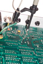
HP 54501 Scope

The
10X
probe
shown above is connected to the HP 54501 scope. Using
this scope to troubleshoot the DG535 pointed out some of it's
problems:
- The digital memory survives power off and so the
scope
remembers all kinds of settings that can cause wrong
answers.
So you must press <RECALL> . . then .
. <BLUE>
to reset
most things to their defaults.
- Next to the buttons for the Delta V and Detla T
readouts the soft label on the CRT has the channel
number to the left
of the cursor value.
When only one channel has any input, say Chan 4 is
being used, and if
the soft label is set for another chanel, say Chan
1, then you will be
using the volts per division and offset setup in
Channel 1 to measure
the on screen voltages, which can give very wrong
answers.
A scope like one of
the Tek
small
USB types is looking pretty good. The other option is
a
Made in China knockoff scope. The TDS2024B looks good.
Ended up getting the
Rigol DS1052E.
Links
Back to Brooke's Time & Frequency,
Personal Home Page, Test
Equipment, Microwave Test Equipment,
PRC68.com
[an error occurred while processing this directive] - page
created
on 2 July 2007
 Currently
measuring
the
difference between a GPS 1 PPS and the output from an
FTS4060/S24 Cesium Standard. The 1 MHz signal from the
Cesium is
the external clock for the counter and it's 1 kHz Reference out is
synchronous with the Cesium input. By using the counter this
way
the time for rollover is improved from 1 micro second to 1 milli
second.


