Vallon Gizmo VMC-1 Metal Detector
© Brooke Clarke 2015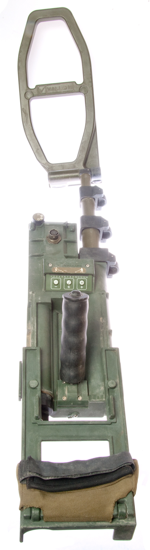
Background
Got this as a non working metal detector. My first impression is that this is not your father's mine detector. It's much smaller and lighter in weight than the other mine detectors I've had.
It seems to have a number of features that can be used programmed.
The type of soil can be either normal or a soil with mineral content and the amount of mineral content can be compensated, either automatically or manually.
The frequency of operation is normally automatically determined from a possible 40 channels. If a group of these units are going to be used near each other then they should be turned on sequentially so that each unit can pick it's best frequency, but you can manually assign the frequency. Also the sensitivity can be adjusted either automatically or manually. I'm not able to try these out because this unit fails the power-up BITE test and will not go past that state.
The Vallon factory is in Germany, but the U.S. Army is testing these.
NATO-STOCK-No. (NSN:) 6665-12-371-0877
Description
After power-up and waiting for the beep beep to change to a steady error tone the loop shows 179.875 & 219.775 MHz on the HP 4395A spectrum analyzer.
Battery
Runs on 3 common "C" cells.
NOTE: the plastic cap needs to be tightened until the metal inside the cap seats on the metal tab in the battery compartment. When I first installed new batteries and powered on nothing happened. It took a short while to discover the problem.
Indicators
Although there's provision for headphones, they are not needed as there's a built-in speaker. There is also a line of 14 red LEDs as a visual indicator. Also a vibration mode, but maybe because of the power-on error it's not active yet?
Connectors
PT07C10-6S is on the metal detector and can be used with a factory headphone or with a factory RS-232 cable for firmware upgrades.
Controls
The rotary knob has 4 positions:
O: Off
N: Normal Soil
M: Mineral Soil
|<: Speaker volume and other adjustments
Joystick Button: for PinPointing metal locations.
Like digital watches there are press, press and hold for single buttons and sequences of buttons and I'm sure the manual does not cover all the combinations.
Photos
Fig 1 Folded for shipment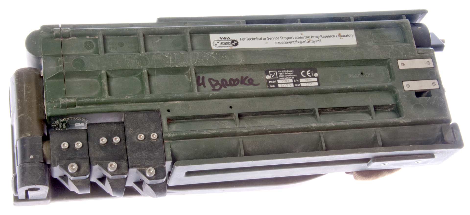 |
Fig 2 Partially opened to show arrangement. Note that a valid operational mode would be with all the telescoping tubes retracted, i.e. to frisk someone. |
Fig 3 Power-up error message LEDs on: 2, 4, 6, 8, 10, 12, 14 (all the even numbers). The manual representation of the LED patterns is difficult to read. Sort of like the DIP switch diagrams that can be read two ways.  |
Fig 4 Display Cover & End Cap Opened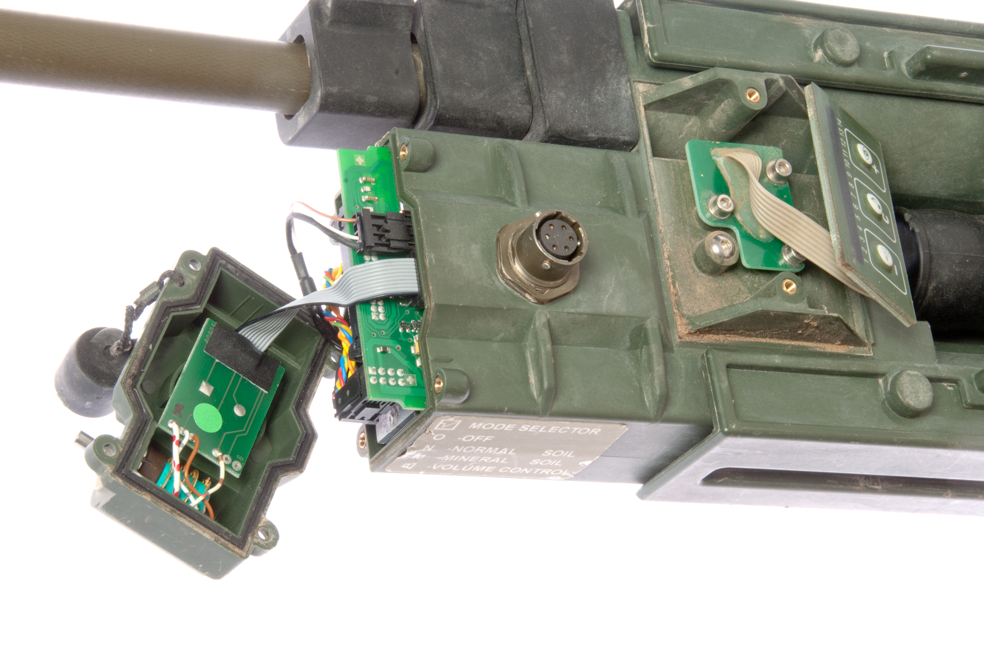 |
Fig 5 Electronics module stopped by hard
wired cables? Poor design or am I missing a trick? 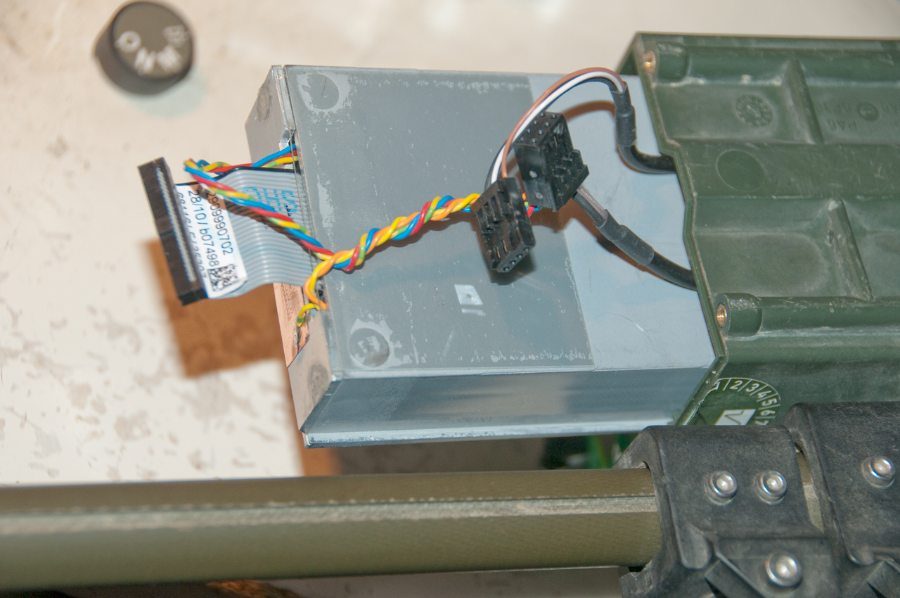 |
The two 2.5mm hex screws aove the display gain access to the display PCB and purging vent screw (?).
After pulling out the coil a little, and removing the knob (2mm hex) you have access to the end cap which can be removed with 4 each 2.5mm hex screws.
The end cap contains the speaker and switch behind the knob.
There's a chassis connection PCB with a ribbon cable to the display, 6 wires to the headset/programming connector and 2 wires (red & blue) to the battery.
This PCB also has four multipin connectors: 2x5 socket for the speaker/knob-switch, 1x4 I'm guessing for the the joystick button (open/0.2 Ohms) & ground and a 2x13 & 2x4 for the electronics module.
The PCB needs to be pulled out to allow disconnecting the multipin connectors and to clear the electronics module.
The electronics module also has hard wiring (a coax cable) on it's 2x4 connector back into the chassis (search coil) 0.4 Ohms.
This is in addition to the coax cable plus a white wire that connects to the PCB 1x4 connector.
Because of this hard wired coax the electronics module does not want to pull all the way out.
How to remove the electronics module?
Related
Newspaper article on Demining that made me aware of the problem of active land mines in civilian populations
PRS-7 Portable Mine Detecting Set
PSS11 PSS-11 Detecting Set, Mine
Sensors many types