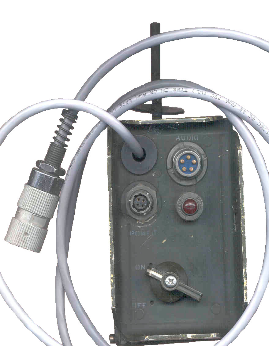
Side Panel
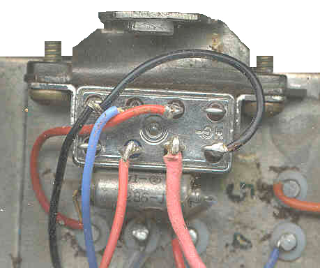
The original cable had rubber insulation on the green, white and black wires that had turned to dust. Someone had made patches inside the box.
I replaced the cable. Used two o-rings (1/2" OD x 5/16 ID - 3/32" wall & 7/6" OD x 1/4 ID ) on the inner side of the box in the cable clamp.
The Audio and power connectors as well as the ON-OFF switch can be removed from the panel with their wires attached without removing the speaker. The power indicator uses a 327 lamp and when the shell is turned CCW three holes allow the lamp to be seen, when turned CW the lamp does not shine.
The Power connector is marked "7204 MSS3114E8-4S" It has 4 Sockets with A = Ground and C= + vehicle supply.
The origional cable had the MIC wire shielded and the overall cable had another shield. I am using plain unshielded 6 conductor cable. In this case I followed the color cade already being used:
- A Ground = Black & Blue
- B Radio Earphone = White
- C PTT = Red
- D Microphone = Green
- E Veh. Power = Orange (new for this modification) connected to the switched vehicle power inside the box
- F Fill = No Connection
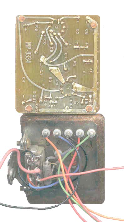
Inside
Speaker is marked with US patent 2755343. This patent covers a speaker that can be submerged in water and that will not rupture when near explosions or gun fire, it's a real military speaker.
In the lower left is the amplifier module. It is mounted with two screws on the left and one on the bottom.
The 1 K Ohm resistor is there just for a test, see Problems below. The plate in the upper left at first looks like a TO-3 socket, but it just holds the 40 Ohm power resistor.Amplifier Module (MP-9334)
Heat sink is Motorola MC1554G
other IC is RCA CA3021
Pin # Function Internal wire color External wire color goes to 1 Input Green Green Radio AUDIO B 2 + Supply Red Red Cathode of 12 V Zener 3 Ground Black Black Ground 4 Mute Blue Blue Relay K1 Blade 5 Output Orange Orange Speaker 6 terminal N.C. Red C1 7 R2 7 terminal N.C. n.a. C1, R2 & CR1 Anode 8 terminal N.C. Red CR1 Cathode & Relay K1 coil Circuit Diagram inside lid, Circuit Diagram Modified for Ext Pwr to Radio
The 1N2976 Zener diode drops the military +24 VDC input to 12 VDC to power the amplifier.
What is inside the amplifier module is unknown. mailto:brooke@pacific.net if you know what the terminals on this module connect to inside.
This unit should work on normal 12 Volt automotive power.The components C1 and R2 (10 uF and 820 Ohms) connected to Amp pins 6 7 & and CR1 (1N647 connected to Amp pins 7 & 8 are a circuit that is in series with the PTT switch of a microphone connected to J1 (if any). When the PTT is pressed it closes relay K1 doing tow things: (1) a contact closes grounding the PTT line on the radio (U-229/U pin C), (2) Grounds the blue wire going to Amp pin 4 Muting the amplifier.
Relay K1
Continous 100 mA, 26.5 VDC, 675 Ohms, Hi-G, Inc., 2K-2299-12, M5757/9-012
B1 NO A2 blade X1 A3 NC Blk Amp 3 Blue Amp 4 Red Amp 8 Coil n.c. n.c. Red Coil R1 & CR2 Blk Amp 3 B3 NC X2 B2 blade A1 NO Data Plate
CX-13143 DC power Cable
This same cableis used for both the AM4979, AM6747 speakers. It is marked:
ICORE 05593, B4005454, CX13143/U (6 Ft 0 In), DAAB07-85-C-K546
The yellow tag attached has FSN 5995-01-101-5467The connector that mates to the AM-4979 is marked: BENDIX 8602 - MS3116E-8-4P
The far end has a Bendix 8602 - MS3111E-8-4P connector (these are both plugs).
I have asked the vendor to replace the amplifier module since I bought this from a retail dealer as "used checked". (18 Feb 2001). More to come.
By wiring the audio pin "E" in the new cable to the switched vehicle power, the radio can be powered from the vehicle, saving it's battery.
This unit should provide about the same functionality as the Datron World MT1060DT, except for the interface to a power amplifier.
Back to Brooke's PRC68, Products for Sale, Photo of Military Audio Accessories, U-229 Audio Accessories, Military Audio, Squad Radio, Military Information, Personal Home
This is the [an error occurred while processing this directive] time this
page has been accessed since since Feb. 18, 2001.