Background
Receiver Operation
DC Power
Connector
Local Oscillator
Top Inside
Patents
CIA Documents
possible description of DZAAS
Related
References
Links
Background
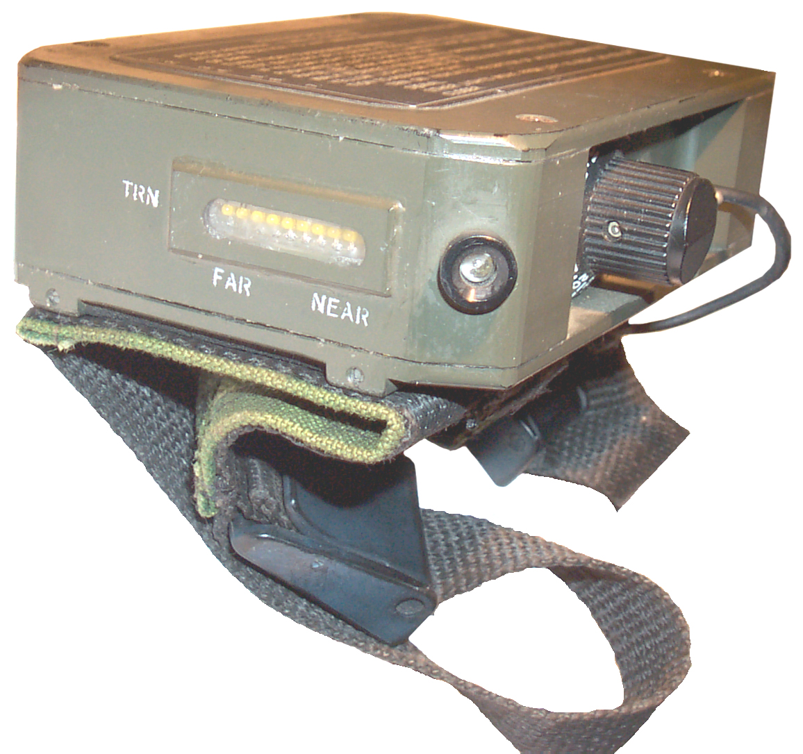
After a parachute drop someone
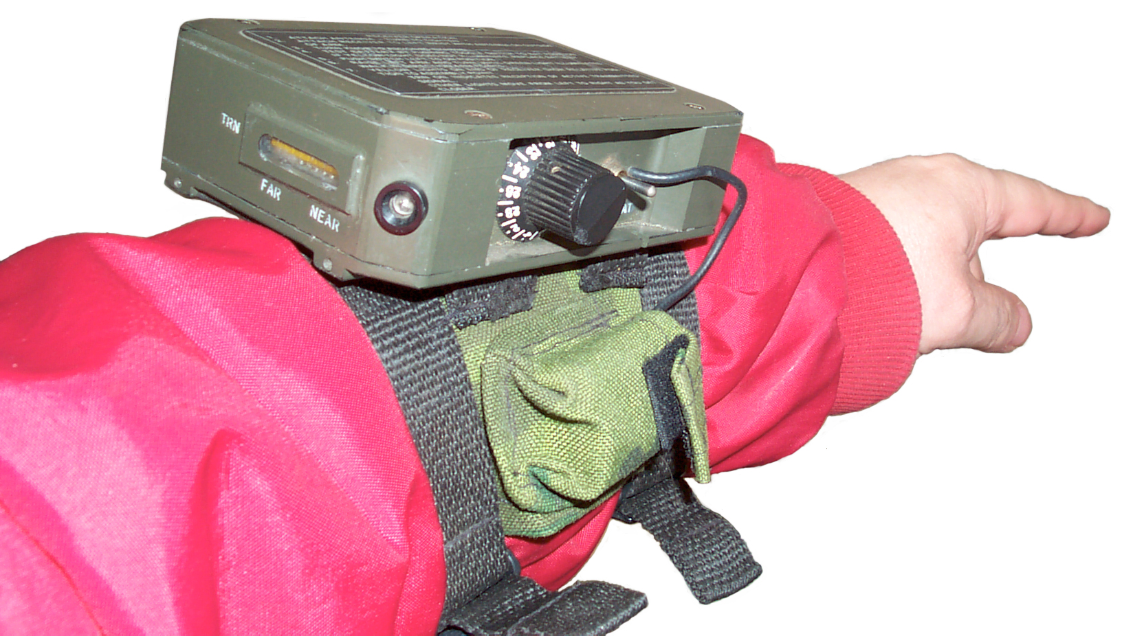
on the ground needs to find the cargo. This 28 channel
receiver is designed to be worn on the left wrist and the LEDs
help to find the beacon transmitter attached to the
cargo. There is a 10 yellow LED bar graph to indicate
distance to the beacon transmitter. This is a
currently fielded system. The top and bottom lids are
sealed to the main body and so it's not designed to be
repaired. Uses surface mount
technology. This was one of the first military
electronics units to make use of surface mount
technology. The parts so far all appear to be standard
part numbers, not custom ICs.
This program was shelved when GPS went operational. My unit has a 1983 contract number and serial No. 110.
I've heard that when the payload is dropped the aircraft that dropped it has a way to come up with Lat & Lon data that can be relayed to the ground crew who only need a common GPS receiver.
This program was shelved when GPS went operational. My unit has a 1983 contract number and serial No. 110.
I've heard that when the payload is dropped the aircraft that dropped it has a way to come up with Lat & Lon data that can be relayed to the ground crew who only need a common GPS receiver.
Receiver Operation
1. Attach Antenna -
Turn to Tighten.
2. Attach Receiver to left wrist with antenna on outside of arm.
3. Turn knob to assigned channel (1 to 28).
4. Test battery by pushing toggle switch to BAT position. If yellow light does not illuminate, replace battery (or connect antenna).
5. Raise left are and turn until green (corner) light illuminates. Walk in direction arm points.
6. Yellow lights on end of receiver show relative position to assembly point. TRN on indicates receiption of active transmitted signal. Other lights move from left to right as you get closer.
DC Power
The 9 volt battery goes into a
pouch that's part of the strap system that holds the receiver
on the left wrist.
Connector
 Patent
5003316
(see below) clearly shows in Fig 6 that both loops and the
sense antenna are inside the case so the connector has some
other purpose. Patent 4724442 (see below) mentions using
rotating antennas which might be the purpose of the
connector. When an external antenna system is not being
used there is some jumper in the mating cap.
Patent
5003316
(see below) clearly shows in Fig 6 that both loops and the
sense antenna are inside the case so the connector has some
other purpose. Patent 4724442 (see below) mentions using
rotating antennas which might be the purpose of the
connector. When an external antenna system is not being
used there is some jumper in the mating cap.The connector has one 0.070" dia pin (pin #1) and three 0.060" dia pins (pins # 2, 3 & 4). It has a plastic body with exterior male threads. I don't see any markings on it. The outside diameter is about 0.692" If If you know the model of the mating connector please let me know.
When a fresh 9 volt battery is
connected and the toggle switch held in the "BAT" position the
yellow LED does not light. Normally this would indicate
a bad battery or missing antenna. When the toggle
is held in the "BAT" position and a screwdriver is used to
randomly short pins in the antenna connector the yellow LED
does light.
 A small
ball of aluminum foil wedged into the connector contacting
pins 1 and 3 causes the BAT test to light the yellow LED next
to the toggle switch. Also the signal strength
yellow LEDs near "FAR" are flickering but the yellow LED
closest to "TRN" is off. I think this is the proper
condition at this stage.
A small
ball of aluminum foil wedged into the connector contacting
pins 1 and 3 causes the BAT test to light the yellow LED next
to the toggle switch. Also the signal strength
yellow LEDs near "FAR" are flickering but the yellow LED
closest to "TRN" is off. I think this is the proper
condition at this stage.
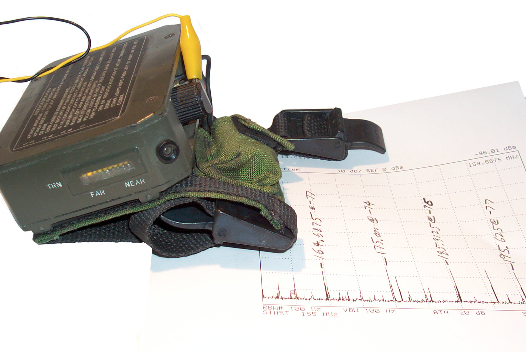
The plot shown in the photo to the left was made with:
the toggle switch =On
Chan 21 (# next to LED)
connector pins 1 & 3 shorted.
The 4395A spectrum analyzer shows new signals at:
164.6875 @ -77 dBm, 175.000 MHz @ -74 dBm, 185.3125 MHz @ -76 dBm and 195.625 MHz # -77 dBm.
Note that the adjacent gaps are all equal to 10.3125 MHz

The antenna consists of both a loop and a sense antenna and these are contained inside the box.
You can see the 9 v battery pouch in the photo at the left and the cable going into the receiver. The LED in the near corner is probably the Green To/From LED that's green when you are pointing To the payload.
Pins 1 (large dia) and 2 are connected toghther. The yellow BAT test LED lights when pins 1 & 3, 2 & 3, 3 & 4 are shorted toghther. But not 2 &4? This may mean that there are two different antennas that can be used. If you know please let me know.
 A small
ball of aluminum foil wedged into the connector contacting
pins 1 and 3 causes the BAT test to light the yellow LED next
to the toggle switch. Also the signal strength
yellow LEDs near "FAR" are flickering but the yellow LED
closest to "TRN" is off. I think this is the proper
condition at this stage.
A small
ball of aluminum foil wedged into the connector contacting
pins 1 and 3 causes the BAT test to light the yellow LED next
to the toggle switch. Also the signal strength
yellow LEDs near "FAR" are flickering but the yellow LED
closest to "TRN" is off. I think this is the proper
condition at this stage.The plot shown in the photo to the left was made with:
the toggle switch =On
Chan 21 (# next to LED)
connector pins 1 & 3 shorted.
The 4395A spectrum analyzer shows new signals at:
164.6875 @ -77 dBm, 175.000 MHz @ -74 dBm, 185.3125 MHz @ -76 dBm and 195.625 MHz # -77 dBm.
Note that the adjacent gaps are all equal to 10.3125 MHz
Local Oscillator
The synthized LO seems to go
from 176.720 MHz for channel 1 to 174.425 MHz for channel 28
so each step is 85 kHz. Typically when the frequency
goes down as the channel number goes up the LO is above the
RF input by the IF. Since the span of the LO is
greater than the common 455 kHz IF the next most likley IF
is 10.7 MHz. So making a slight tweak to the LO
frequencies moves them to:
Chan 1: 176.700 MHz LO - 10.7 IF = 166.000 MHz RF input
Chan 28: 174.405 MHz LO - 10.7 IF = 163.705 MHz RF input
Chan 1: 176.700 MHz LO - 10.7 IF = 166.000 MHz RF input
Chan 28: 174.405 MHz LO - 10.7 IF = 163.705 MHz RF input
The antenna consists of both a loop and a sense antenna and these are contained inside the box.
You can see the 9 v battery pouch in the photo at the left and the cable going into the receiver. The LED in the near corner is probably the Green To/From LED that's green when you are pointing To the payload.
Pins 1 (large dia) and 2 are connected toghther. The yellow BAT test LED lights when pins 1 & 3, 2 & 3, 3 & 4 are shorted toghther. But not 2 &4? This may mean that there are two different antennas that can be used. If you know please let me know.
Top Inside
 In order to open the
lid the four screws were removed and a dead blow rubber hammer
used to crack the glue used to seal the lid to the box.
The bottom lid has not yet succumbed to the hammer so more blows
are needed to get it off.
In order to open the
lid the four screws were removed and a dead blow rubber hammer
used to crack the glue used to seal the lid to the box.
The bottom lid has not yet succumbed to the hammer so more blows
are needed to get it off.This photo shows the top lid removed and the digital PCB hinged out. In the bulges beside the channel switch and the battery wire are two 5 turn coils oriented at right angles to each other and each has a variable trim cap. These are the two orthogonal loop antennas.
Patents
The Class 342/4xx seems to be common to both of the E-systems patents for the DZAAS and as of 7 Jan 2007 there are 7810 patents in the linked search.5003316 (.pdf) Single null miniature direction finder March 26, 1991, , E-Systems, Inc., 342/429 ; 342/419
A single null miniature
direction finder which may be worn on the arm of the user and
is fully automatic in operation. Signals from a single loop
antenna and a sense antenna are summed; however, the amplitude
of the sense signal is adjusted at first and second phase
angles and the phase of the sense antenna is automatically
switched from the first phase angle to the second phase angle
prior to summing to produce either a single null or a no null
pattern. These patterns are compared to each other as the user
extends his arm horizontally and rotates his body. When the
null occurs an indicator gives the relative direction to the
transmitter.
4724442
(.pdf)
Method and apparatus for loop direction finding with no
ambiguity Feb 9, 1988, E-Systems, Inc. 342/434 - uses two loops
and a sense whip antenna. Replaced by 5003316 that uses
only one loop and a whip sense antenna. Includes 28
channel switch and LED indicator.This patent mentions Contract DAAK20-83-C-0639 which is the contract number on the DZAAS label. This patents olso shows a 28 position channel switch.
The below patents relate to direction finding
5706010 Method and apparatus for determining location of an unknown signal transmitter Jan 6, 1998, E-Systems, Inc.342/47 ; 342/13; 342/147; 342/193; 342/417 - The locator device transmits a pulsed signal that's close to the unknown transmitters frequency. This causes intermodulation distortion to occur in the unknown transmitter. By measuring the time from sending the pulse to the time when the 3rd order IM return signal arrives an estimate of the distance to the unknown transmitter is calculated. The power level of the interrogating signal is not mentioned.
5502450 Single antenna direction-finding system March 26, 1996, E-Systems, Inc. 342/451 ; 701/300 - not DZAAS but instead intended for use on an aircraft.
5461387 Position and direction finding instrument Oct 24, 1995, Georgia Tech Research Corporation, 342/357.08
5394161 Path finder/tracker system Feb 28, 1995, John & Richard Ubaldo, 343/702 ; 33/290; 343/894; 701/224
4876549 Discrete fourier transform direction finding apparatus Oct 24, 1989, E-Systems, Inc., 342/417 ; 342/194; 342/195
4489327 Direction finding Dec 18, 1984, Racal, 342/432 ; 342/433
4410890 VHF Directional receiver October 18, 1983, United States of America as represented by the FCC, 342/419 ; 343/767; 455/269; 455/351; D10/65 - VHF slot antenna and non conductive tube to earpiece for covert operation
4003060
Direction
finding receiver Jan 11, 1977, United States of America as
represented by the FCC, 342/419 ; 455/333; 455/351; D10/65 -
CB radio by channel number
4263597 Nondisruptive ADF system April 21, 1981, United States of America as represented by the FCC, 342/434 ; 342/435; 342/436; 342/438 - does not disturb the modulation like doppler type DF sets
4121216
Direction finder antenna and system Oct 17, 1978, E-Systems,
Inc., 342/424 ; 343/728 - uses crossed vert loops & sense
antenna PLUT a horizontal loop to detect sky waves.4263597 Nondisruptive ADF system April 21, 1981, United States of America as represented by the FCC, 342/434 ; 342/435; 342/436; 342/438 - does not disturb the modulation like doppler type DF sets
Related
DIRECTION FINDER RECEIVER DZ-2 CRV-46152 28 VOLTS DC this is an RCA tube type aircraft receiver. Not sure if it's also a Drop Zone type radio or general D.F. radio.Black Box - transmits around 164 MHz pulses maybe 600 uS wide.
IR Beacon - snaps on 9V battery
SDU-5 strobe distress beacon- can be equipped with IR filter
CIA
Documents
Drop
Zone Beacons 1951 - need for IR beacon visible from
aircraft to guide paratroopers.Report on a Preliminary Investigation of Factors Influencing the Design of a Lightweight Paratroop Beacon, 1951 - design constraints for an X-band beacon
Discussion with Signal Corps about Field Marking Equipment, Drop Zone and Night Landing 1951 - Fluorescent and phosphorescent materials, aircraft mounted IR viewer so pilot doe need to wear special goggles, SE-11 5-cell flashlight with IR filter, UV activated fluorescent material,
Field Marking Equipment (Drop Zone and Night Landing)(RDP-60) - 1951 - DZ: use fluorescent ultraviolet-autocollimator illuminated by BH-6 or AH-8 UV light on plane. Night Landing: use Welshback mantle gasoline lamp (Wiki) with IR filter.
Field Marking Equipment (RDP-60), Beacon, Field Marking, Infrared (RDP-60A), Night Landing System, Ultraviolet (RDP-60B) - Progress Report and Request for Requirements 1952 -
IR: Coleman w/IR mods (used with Metascope (similar to PAS-6) to work at night) the aircraft could use: M-2 Snooperscope, Electronic Viewer US/C3, IR Binoculars, Image Metascope. Ground viewers: US/F Metascope, Image Metascope, US/AM Metascope.
UV: UV light source in plane and fluorescent auto-collimator on ground. Originally designed to guide ships into harbors in W.W.II.
Field Marking Equipment (RDP-60)- Tests of Beacon, Infrared 1952 - C-47 Plane: M2 Sniperscope, Radio Firing Device Transmitter, Handie Talkie, Ground: [redacted], 6 beacon lamps, Firing device, Radio Detonator (VHF), Radiophone pack, Image Metascope, 2 IR flashlights. hard to separate real beacons from other lights, a flashing light would help.
SARAH Drop Zone (DZ) Location Equipment 1954 - 235 Mc +/- 0.1 Mc 7uS wide pulse with 100 to 300 uS pulse spacing (coding)
Status Report Project 2039 Drop Zone Beacon Program 1956 - started in 1952.
Systems investigated:
British Gee and Consul, American LORAN and SHORAN.
VOR Omnirange.
S & X band radar
Rebecca-Eureka
Infrared Beacon, Viewrs and Metascopes.
AN/ARA-8 vs. AN/URC-4 (VHF)
AN/ARA-25 vs. AN/URC-4 (UHF)
AN/CRT-3 (Gibson Girl) and other small transmitters.
The URC-4 with a modification to mount on a tripod with a 5/8 wave ground plane antenna was the best.
The ARA-8 is a VHF system using a pair of antennas and indicates by a "U" or "D" Morse code tone in the pilot's headset. It works with the ARC-3 transceiver. Needs a visual pointer type indicator for the needed accuracy.
SARAH :
Ground based (Fig 6 pg 18) pulse transmitter at about 220 Mc paired pulses with a 5 mS interval. A number of different beacons can operate at the same time and be distinguished from each other.
Aircraft (fig 5 pg17): Dual yagi antennas, CRT indicator, C-47 or helicopter,
Voice communications are very poor.
Final Report in the Ferrite Antennas for Very Low Frequencies 1957, 61 pgs - aimed at submarine reception of 25 kHz RTTY.
R&D
Lab Support of Drop Zone Beacon Program 1957 - SARAH
beacon Project Initiation From R&D Lab
Beacon Flight Tests 1957 - stock URC-11 (240 Mc) and two each Mk 220 SARAH beacons (213.5 Mc) also a modified URC-11 (240 Mc) and two each TSS transponder beacons.
Beacon Flight Tests 1957 - stock URC-11 (240 Mc) and two each Mk 220 SARAH beacons (213.5 Mc) also a modified URC-11 (240 Mc) and two each TSS transponder beacons.
Conference Report, Drop Zone Beacon Program 1958 - CIA beacon program, Ground set Tx on 1200 kHz compatible with aircraft ADF,. Uses "unique" transmission method. maybe the Light Weight Beacon. Not all aircraft have S-band or X-band radar equipment so a beacon in those bands is not suitable. An option might be a sonobuoy - RADAR cross band system which would require an on/off switch for the aircraft RADAR.
Drop
Zone Beacon Tests 1959 - helicopter: 300# 25 cu
ft. ground: ?
Beacon Requirements 1959 - similar to Development of DZ Beacon below.
Development of Drop Zone Beacon 1959 -
Characteristics of the System:
1. Guide helicopter at 200 - 300 feet and 15 miles out.
2. Transmit a minimum amount of signal consistent with the success of the mission, with the major ephhasis placed on accuracy.
3. Operate without visual reference to the ground.
4. Reasonable free of local interference or enemy jamming.
Airborne Req:
1. Weight no over 50 pounds.
2. Minimal signal emission from aircraft consistent with obtaining an accuracy of 10% in residual range and 50 feet in azimuth over the DZ marker.
3. Visual signal to crew members to include range and azimuth.
4. High reliability.
Ground Req:
1. Readily carried by one person.
2. [redacted] Guess a stealth signal so the enemy can not hear it.
3. Weight under 10 pounds.
4. If a power source is required, it should have a shelf life of at least six months or be rechargeable by a hand generator, solar or therom-couple chargers. It should operate the equipment continuously for at least 10 hours.
5. Limited emission consistent with range requirements.
6. adaptable to hot, cold, humid climate.
7. Simple to erect and operate.
8. High degree of reliability and accuracy.
9. Should meet CIA standards of sterility.
10. Voice transmission is an optional requirement, but a simple system of coding would be desirable in order to maintain a limited secure contact between the ground and the crew.
Radio Set-Beacon AN/GRN-8 1960 - Motorola data sheet - 30 - 39.95 Mc, 200 channels, 5 Watts, FM, Transpond, CW & Voice.
Compatibility: ARC-44, ARC-54, ARA-31, PRC-10
Drop Zone Location Aids 1960 - Modified Coleman lantern IR beacons & IR red plastic filter material.
Technical Proposal X III HRT-2 Beacon Transmitter Production 1961 - 1500 - 1800 kc, Crystal controlled, 15 Volt battery or ext supply, >10 Watts out, 1 or 2 kc audio tone, more specs.
delivery sched:
10 HRT-2 & 20 battery packs: Jan 1, 1961
50 HRT-2 & 100 battery packs: Jan 15, 1961
100 HRT-2 & 200 battery packs: Jan 30, 1961
Medium Frequency Drop Zone Beacon, HRT-2 1961 - 1600 - 1800 kc, 10 Watts out, A-42 balloon 150' antenna, 16' whip, Mercury battery pack or hand crank generator T9D, Thermo-electric power source HFP-1. Wesponder Beacon: 1670 kc
Beacon Test Program 1961 - HRT-1 (Wesponder) and HRT-2 (MF ADF beacon) were tested in 1961. The HRT-2 worked well with the Lear ADF receiver outperforming the ARN-6 in range. HRT-1 only marginally useful.
Problems with HRT-t Beacons 1961 - Meting minutes: color code ant terminals: red hot and black ground, longer battery cable, "hot" transmitter housing with using 16' antenna, use captivated screws,
Project Plan for Radio Set RS-8 Project No. 2054 1980 - Cargo Chute Beacon Transmitter (Not RS-8 radio) -
Characteristics of Cargo Chute Locator System 1980 - CIA-RDP78-03535A001800010020-8.pdf
Accomplish the following:
a. Aid in locating a cargo parachute dropped on a re-supply mission where the recipent is already on the ground in the drop area.
b. Aid in locating a cargo chute when it and the recipient are dropped at approximately the same time.
c. Aid in tghe rendezvous of a number of chutists who have dropped into the same general area at about the same time.
Beacon Requirements 1959 - similar to Development of DZ Beacon below.
Development of Drop Zone Beacon 1959 -
Characteristics of the System:
1. Guide helicopter at 200 - 300 feet and 15 miles out.
2. Transmit a minimum amount of signal consistent with the success of the mission, with the major ephhasis placed on accuracy.
3. Operate without visual reference to the ground.
4. Reasonable free of local interference or enemy jamming.
Airborne Req:
1. Weight no over 50 pounds.
2. Minimal signal emission from aircraft consistent with obtaining an accuracy of 10% in residual range and 50 feet in azimuth over the DZ marker.
3. Visual signal to crew members to include range and azimuth.
4. High reliability.
Ground Req:
1. Readily carried by one person.
2. [redacted] Guess a stealth signal so the enemy can not hear it.
3. Weight under 10 pounds.
4. If a power source is required, it should have a shelf life of at least six months or be rechargeable by a hand generator, solar or therom-couple chargers. It should operate the equipment continuously for at least 10 hours.
5. Limited emission consistent with range requirements.
6. adaptable to hot, cold, humid climate.
7. Simple to erect and operate.
8. High degree of reliability and accuracy.
9. Should meet CIA standards of sterility.
10. Voice transmission is an optional requirement, but a simple system of coding would be desirable in order to maintain a limited secure contact between the ground and the crew.
Radio Set-Beacon AN/GRN-8 1960 - Motorola data sheet - 30 - 39.95 Mc, 200 channels, 5 Watts, FM, Transpond, CW & Voice.
Compatibility: ARC-44, ARC-54, ARA-31, PRC-10
Drop Zone Location Aids 1960 - Modified Coleman lantern IR beacons & IR red plastic filter material.
Technical Proposal X III HRT-2 Beacon Transmitter Production 1961 - 1500 - 1800 kc, Crystal controlled, 15 Volt battery or ext supply, >10 Watts out, 1 or 2 kc audio tone, more specs.
delivery sched:
10 HRT-2 & 20 battery packs: Jan 1, 1961
50 HRT-2 & 100 battery packs: Jan 15, 1961
100 HRT-2 & 200 battery packs: Jan 30, 1961
Requirement
for Hand Crank Generator F/U/W HRT-2 1961 -
HRT-4 (aka: BN-2) Homing Radio Beacon works with
GN-58 hand crank generator. But the HRT-1 and
HRT-4 are no longer being purchased.The HRT-2
requires 15 to 20 VDC at up to 2 Amps which no
current hand crank generator supplies. A
thermo-electric power supply running on kerosene is
coming.
Medium Frequency Drop Zone Beacon, HRT-2 1961 - 1600 - 1800 kc, 10 Watts out, A-42 balloon 150' antenna, 16' whip, Mercury battery pack or hand crank generator T9D, Thermo-electric power source HFP-1. Wesponder Beacon: 1670 kc
Beacon Test Program 1961 - HRT-1 (Wesponder) and HRT-2 (MF ADF beacon) were tested in 1961. The HRT-2 worked well with the Lear ADF receiver outperforming the ARN-6 in range. HRT-1 only marginally useful.
Problems with HRT-t Beacons 1961 - Meting minutes: color code ant terminals: red hot and black ground, longer battery cable, "hot" transmitter housing with using 16' antenna, use captivated screws,
Project Plan for Radio Set RS-8 Project No. 2054 1980 - Cargo Chute Beacon Transmitter (Not RS-8 radio) -
Characteristics of Cargo Chute Locator System 1980 - CIA-RDP78-03535A001800010020-8.pdf
Accomplish the following:
a. Aid in locating a cargo parachute dropped on a re-supply mission where the recipent is already on the ground in the drop area.
b. Aid in locating a cargo chute when it and the recipient are dropped at approximately the same time.
c. Aid in tghe rendezvous of a number of chutists who have dropped into the same general area at about the same time.
Wireless for the Warrior - Vol 4 Supplement, Chap. 66-1 AN/URC-4 Country of origin: USA Apr 2016 - photos of modified URC-4 radio, horizontal "X" antenna
References
Ref 1. Wiki: Joint Precision Airdrop System -
Ref 2. YouTube Search "Joint Precision Aerial Delivery System"
Links
MONTEK WINS $2.2 MILLION ARMY CONTRACT Dec 14, 1988 - "The system uses radio direction finding techniques to establish an assembly point by deploying a small transmitter. Troops using small, battery powered, wrist-worn receivers may quickly locate the assembly point by homing in on the transmitter signals." That suggests that the Black Box is the associated transmitter?[an error occurred while processing this directive] page created 5 Jan 2007.