Flywheel - Pulley
© Brooke Clarke 2015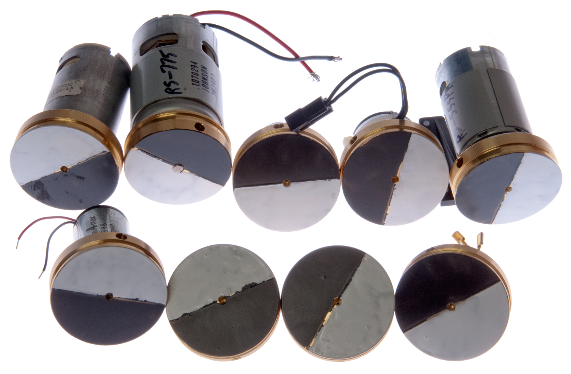
Background
Description
Basic DC PM Motor Theory
Flywheel Theory
Motor Experiments
Photos
Related
References
Links
Description
Basic DC PM Motor Theory
Flywheel Theory
Motor Experiments
Photos
Related
References
Links
Background
The classical flywheel (Wiki) is used typically with various engines (Wiki) to smooth out the power to drive a load. They also can be used as energy storage devices. A pulley (Wiki) is a disk that can turn on a shaft and has a groove to engage a drive belt or something like a rope. A gear (Wiki) is similar to a pulley but has teeth that engage other teeth on another gear.
This web page started out with my interest in DC permenant magnet samll motors. It turns out to do experiments on these you need a gear, pulley or flywheel so that a string can be connected to the motor with some known radius or circumference so that calculations can be made on how the motor is working.
Since I also wanted to see if a flywheel on small DC motors would act as a gyroscope I wanted a single device that would fulfill many requirements and so set out to design and make it.
It turns out that this flywheel is about the same size as the one used for the Super Gyrpscope made in the UK.
Description
This flywheel is intended to be used in a number of different applications. I have a number of small DC permanent magnet motors with a shaft diameter of 3.17mm (1/8") and so that's the flywheel I'm starting with. There are other DC PM motors with larger and smaller shafts so this idea could be repeated by simply drilling a different size hole in the flywheel.
1) As part of a de Prony Brake (Wiki) where having the circumference be 6" (1/2 of a foot) makes the horsepower (Wiki) calculations much easier. The belt used a a Hoover Upright Vacuum Cleaner (See belts on Coil Winder web page) would be ideas for this because when the brush on the vacuum gets jammed the flat belt gets extremely hot and does not instantly break, that's to say these belts can take quite a beating. In this case the flywheel is spinning at some RPM and the torque is measured at that speed.
2) As part of a setup for measuring the stall torque (Wiki) of the DC motor at various currents where a string is attached to the OD of the flywheel with either a weight or a pull scale.
3) As part of a gyroscope (Wiki) where the motor will be turning at high speed. I don't have a feel for this based on calculations, but know that the Mabuchi DC permanent magnet motors I have show some gyroscope properties when run without anything connected to the shaft so I expect that by adding a flywheel they will have a lot more gyroscopic action. Note that flywheels are not typically used with DC motors, probably to avoid any gyroscopic effects.
4) It may be possible to use just the flywheel's moment of inertia to measure the torque curve of the motor. Most Dynamometers (Wiki) work by applying a load on the motor while it's running. This means that the dynamometer must dissipate the power being output by the motor. But with the inertial sweep (Wiki) test method the power goes into the kinetic energy (Wiki) of the flywheel. So if the motor is powered when the flywheel is at rest the motor will output it's stall torque and draw it's stall current. If the flywheel a rotational moment of inertia (Wiki) that's too high the motor will burn up before coming up to speed. If the rotational moment of inertia is too small the flywheel will come up to the motor's no load speed very quickly so there will not be enough time to record data. It's possible to calculate how long it will take for a given motor to come up to speed with a given rotational moment of inertia flywheel. There's a complicating factor in that the no load speed of the motor will be higher without the flywheel than with the flywheel attached because of the air resistance of the flywheel. Maybe a vacuum chamber could separate those two effects?
5) Testing DC motor as generator. It turns out that the add-on type sewing machine motor w/foot speed control that's used to electrify a treadle (Wiki) sewing machine (Wiki) that I got to power a coil winding machine can also be used to drive a motor by means of the flywheel/pulley. By using a motor mount bracket that's compatible with the Open Beam system a couple of motors can be mounted side by side and mechanically connected by a sewing machine belt or an O-Ring belt.
6) It turns out that by painting the front face of the flywheel half black and half white, see photo at top of page, an optical tachometer can be used to measure the RPM of the motor. This is one of the key motor parameters.
Basic DC PM Motor Theory
There are some simple linear relationships that do a pretty good job of describing the operation of a DC PM motor.
See the DC PM Motors Basic Theory section.
Also see my Testing DC Motors web page.
Flywheel Theory
The key parameter of a flywheel is it's rotational moment of inertia (Wiki: List of moments of inertia) but all the shapes in the Wiki list are for the moment of inertia about their center of mass. To translate to the actual center of rotation you need to use the Parallel axis theorem (Wiki) or the Perpendicular axis theorem (Wiki). The Stretch Rule (Wiki, Stanford) can be used to simplify real world shapes into shapes that are easier to analyze.
I started to balance the flywheel design by using moment of inertia (MOI) calculations, i.e. started with dynamic balancing, but soon discovered that the moment of inertia of those things that are at the longest radius are the most important because the MOI goes as the radius squared. So best to start with static balance and pay a lot of attention to the tap clearance hole.
The first step after designing the flywheel was to static balance it by adding a drilled hole opposite to the tap clearance hole. If the set screw is about the same length as the tapped hole then to get static balance the depth of the balance hole is only a little different from the tap clearance hole.
When acting as a gyroscope (Wiki)
Moment of Rotational Inertia
For a solid disk rotating about is axis the inertia is given by (Wiki)
I = 0.5 * M * R*R = 0.5 * 204 grams * 2.54cm * 2.54 cm = 658 g-cm2
Compare this to first generation spinning wheel gyroscopes where I is on the order of a f
The wheel used by Leon Foucault was about this size, so it should work to repeat his experiments, but probably is way too small to use as a gyrocompass for any moving vehicle.
Motor Experiments
See Testing DC Motors.
Photos
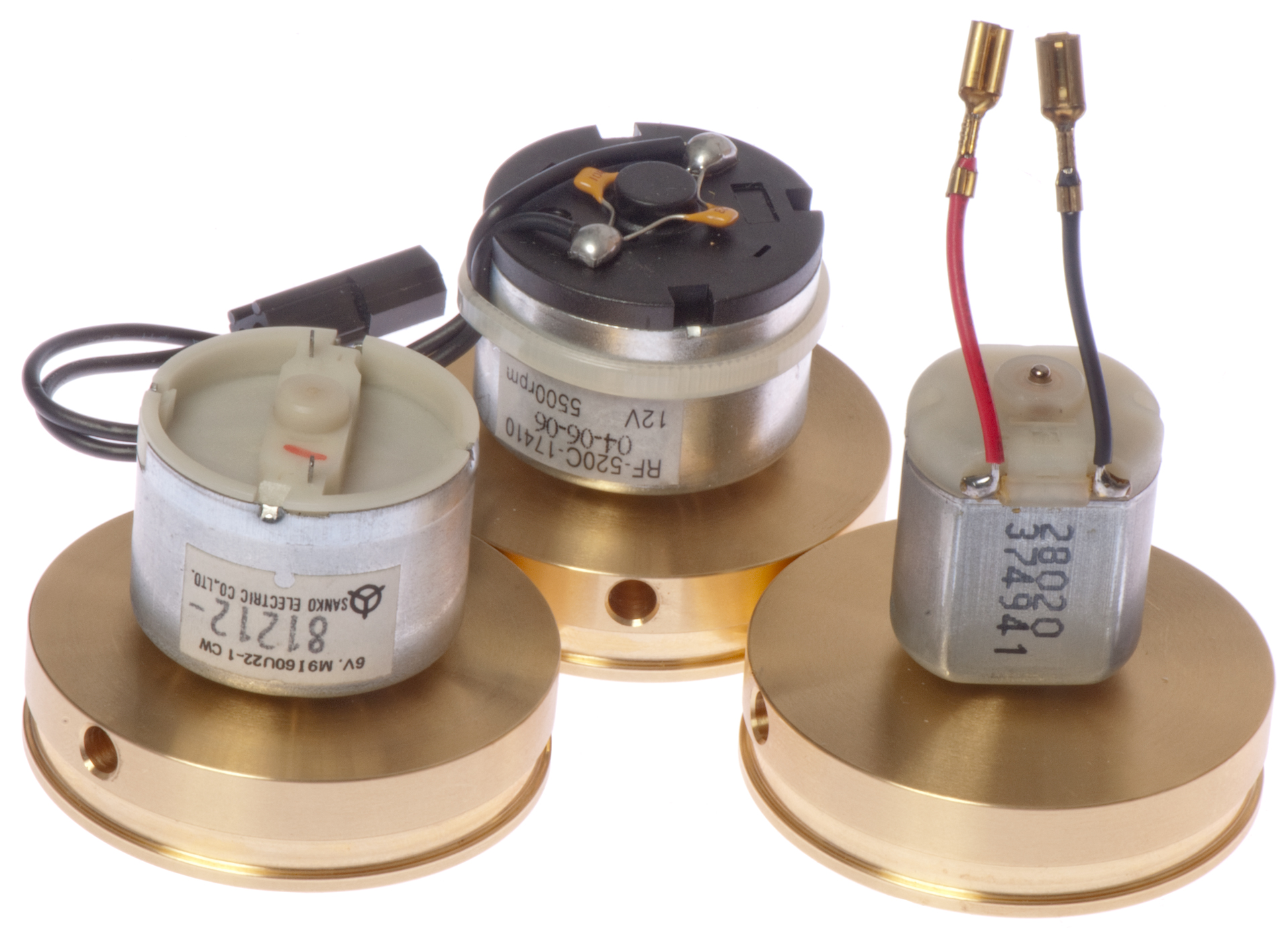
All of this group of flywheels have a circumference at the bottom of the pulley groove of 6.000" (just under 2" OD). They differ in the hole diameter for the motor shaft.
Motor shaft sizes not in first batch but for which there are motors: 2.3mm & 3.0mm
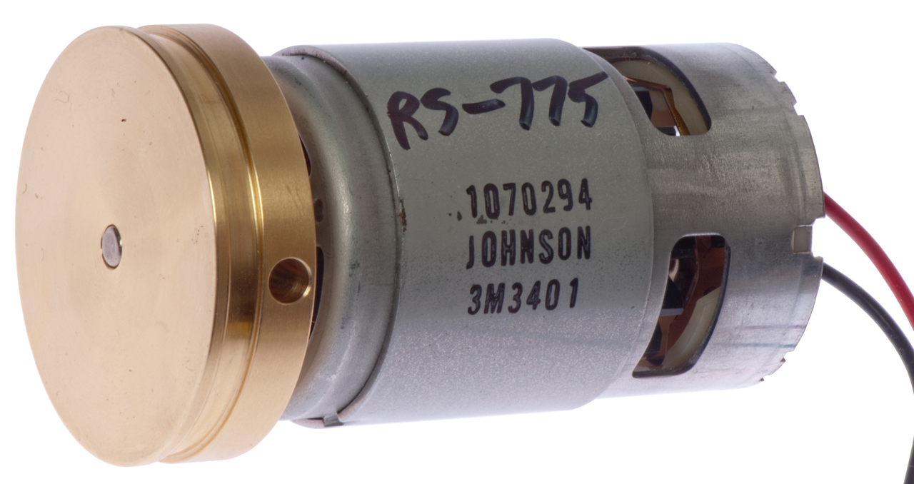
2" dia x 5.0 mm shaft Flywheel
Johnson 1070254, 3M3401 (RS-755) DC PM motor
2" dia x 4.0 mm shaft
No motor yet.
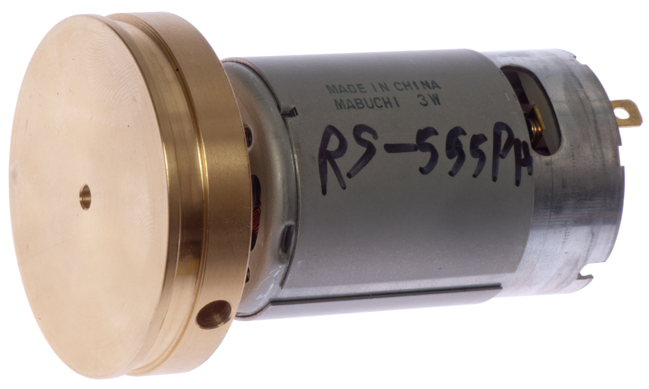
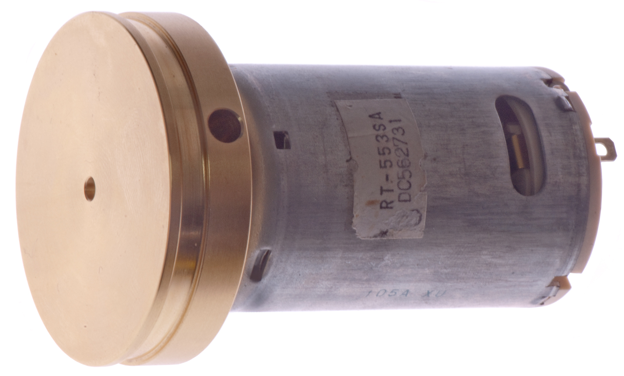
2" dia x 3.17 mm shaft Flywheel
Mabuchi RS-555 DC PM motor
Mabuchi RS-553SA motor w/ 3.17mm shaft
2" dia x 2 mm shaft Flywheel
Surplus DC PM motors - this would be a good motor size for battery power.
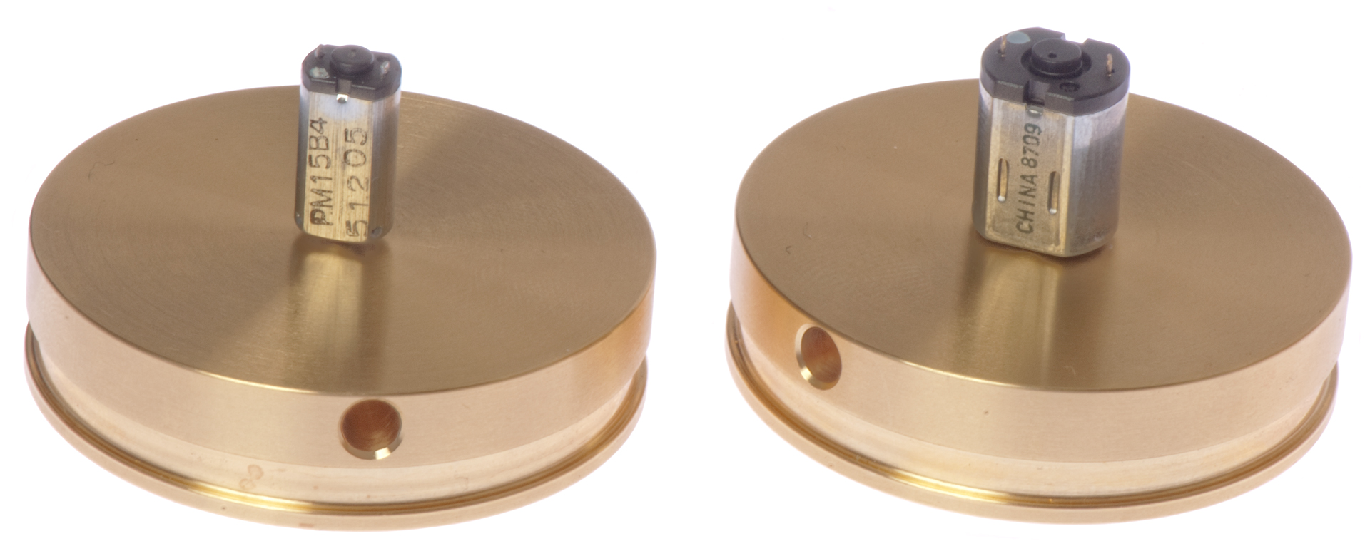
2" dia x 1.0 mm shaft Flywheel
The motor shaft bends because of the set screw.
Maybe Loctite for attachment would prevent this?
Surplus DC PM motors - needs development
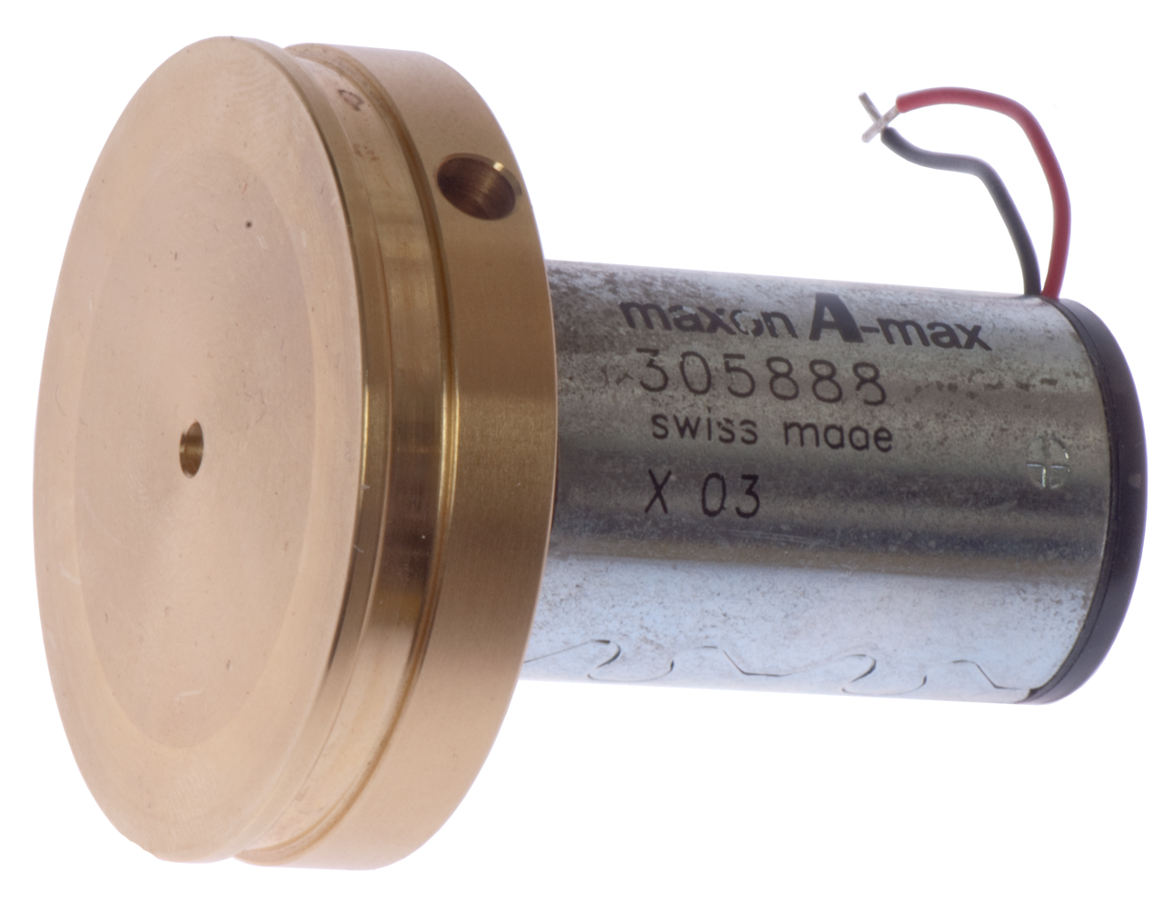
2" dia x 3.17 mm shaft Flywheel
Moxon A-max, 305888, x03 has a 3.0mm shaft & fantastic bearings But flywheel is out of balance because hole is for 3.17mm shaft. It's not objectionable but there is a high frequency "buzz".
2" dia x 2.3mm shaft Flywheel.
A #42 drill will easily enlarge a 2mm hole and make it a 2.3mm hole, so now I can test some 2.3mm shaft motors.
Related
DC Gaussmeters & magnetic testers
DC Permenant Magnet small motors
Testing DC Motors - YouTube
Gyroscopes - YouTube
Helmholtz coils - a way to measure the strength of a permanent magnet
High Field magnet - TBD - It's difficult to generate a magnetic field of 1 Tesla (Wiki) which is equivalent of 10,000 Gauss (Wiki). Since the Earth's magnetic field (Wiki) has a total vector strength of about 1/2 Gauss, a 1 Tesla filed would be 20,000 times stronger than the Earth's field.
References
Links
PRC68, Alphanumeric Index of Web pages, Contact, Products for Sale