Testing Small DC PM Motors
© Brooke Clarke 2015 - 2019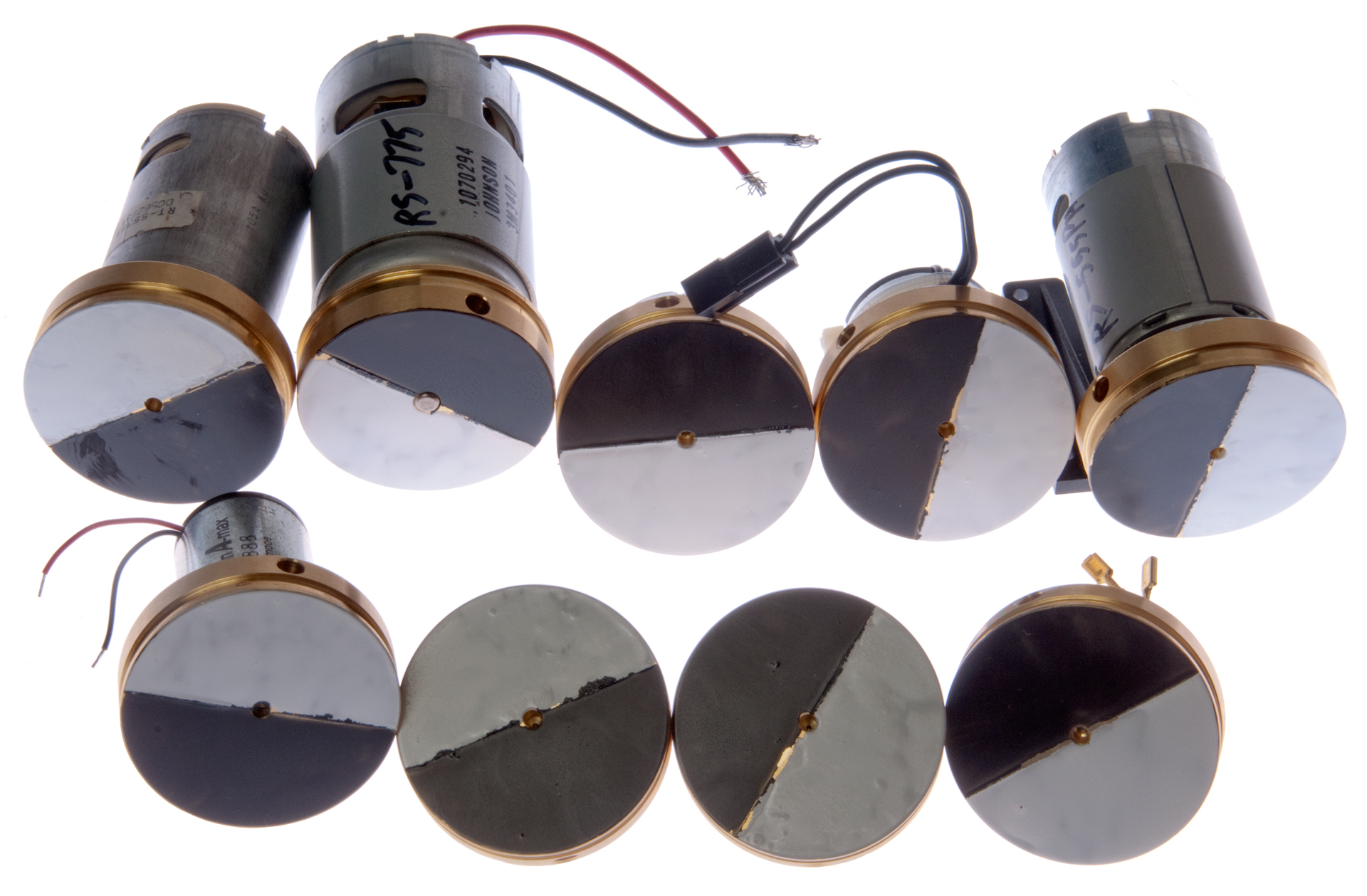
Description
Basic DC PM Motor Theory
Back EMF
Kv
Calculate Torque Constant
Stall prediction
Winding Difference
Ki
Table From Kv to Ki
Motor Resistance
Battery Resistance
Shaft Diameter
Videos
Testing Unknown Motors
Related
References
Links
Background
This page is about testing small DC PM Motors that have a flywheel installed. So far these motors have a shaft diameter between 1.0 and 5.0mm and so there is a family of flywheels that all are about 2" in diameter but differ in the shaft hole size.
Description
The flywheel has been painted black and white to help measure the RPM.
Basic DC PM Motor Theory
One point of a plot where torque is the independent variable would be the no load RPM and the nominal voltage. The other point would be the stall current and torque.
With no load the motor spins as fast as it can and is doing no useful work. When it's loaded there is some torque doing work, the RPM goes down and the current increases.
Back EMF
The battery voltage drives the motor. When the motor is stalled (the flywheel is not turning) the torque is determined by the current through the armature.
When the motor is allowed to spin and is at a constant RPM a back EMF (Wiki) is generated in a direction to buck the battery so that the actual voltage drop across the armature is the difference between the battery voltage and the back EMF.
Kv (aka Turns or T)
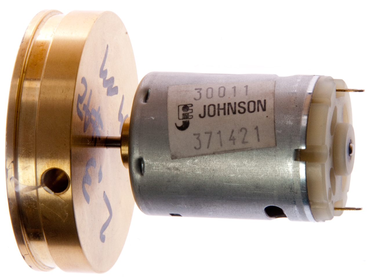
The motor used for this test and the video below is the RS-555PH.
The back EMF constant that show a linear relationship between motor speed and voltage. It can predict the no mechanical load speed of a motor or the generator output at a given RPM when there's no electrical load.
Kv (RPM/Volt) is the RPM divided by the Voltage when there's no load. (Pretty close to when the motor is running at no load).
This is also the relationship between RPM and Back EMF when there's no external load on the motor, i.e. as measured by a DMM.
If a load is applied then the Back EMF is in a voltage divider where the generator internal resistance and the load resistance cause a voltage drop.
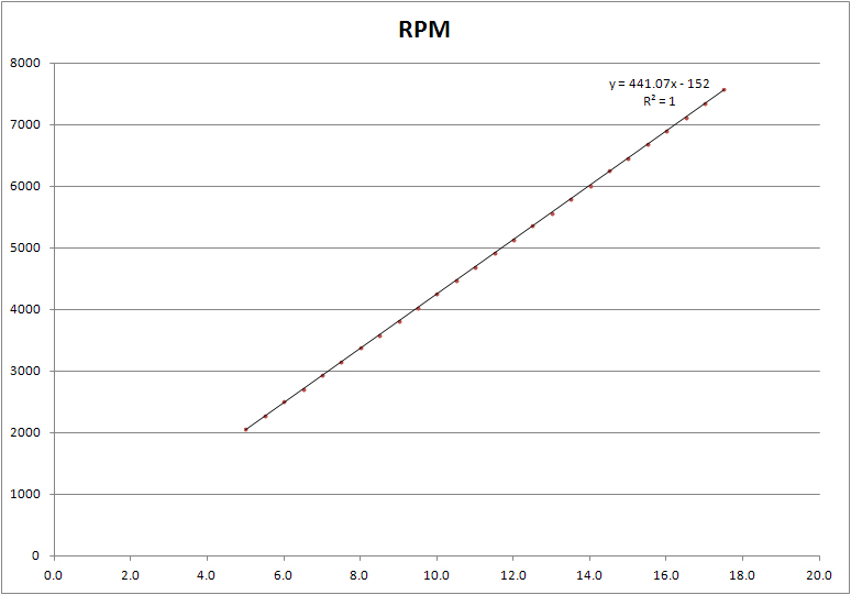
In order to get some statistical averaging I tested the motor from 0 (silly) to 17.5 Volts in 0.5 Volt steps.
It turns out that this RS-555PH motor will not turn over at 0.5 Volts, even when the flywheel is turned by hand, so the first data point is at 1.0 Volts.
But the data points below 5.0 Volts when plotted do not fall on a straight line, but from 5.0 to 17.5 Volts the points fit a straight line well (R2=1)
RPM = 441.07*V - 152
Kv (RPM/V) =441 RPM/Volt = (441 Rev/min Volt) * (1 min/60 sec) = (7.3 Rev/Sec)/Volt = 46.18 Radians/(Volt Second)
Ke = 1/Kv = 0.0217 (Volt seconds)/Radian
Calculate Torque Constant
Here's the magic part that only applies to DC PM Motors
Kt = Ke (when both are in SI units)
Kt = 0.0217 (Newton meters)/Amp
Solving the equation for RPM = 0, gives +0.34 Volts as the starting voltage. Not sure about way, let me know.
This may be a measure of the "cogging" (Wiki).
Note this offset may be what keeps the straight line from going through the nominal operating point.
The RPM you get from using the straight line at 12 Volts is different from the actual RPM at 12 Volts.
RPM = 441.07*Volts - 152
R2=1
The data sheet for the Mabuchi RS-555PX- shows 4500 RPM at 12 V or 375 RPM/Volt.
There are two torque points on the data sheet:
Max efficiency 3960 RPM, 0.95 Amps, 19.4 milli-Newton meters (0.0194 Nm) or Kt=0.0204 Newton meters/amp)
Stall: 0 RPM, 7.0 Amps 162milli-Newton meters (0.162 Nm) or Kt = 0.0230 Newton meters/amp
Note that both torque constants are very close to 0.02 Newton meters/amp.
Stall prediction
From the Kv measurements at 12.0 volts applied to the motor the RPM was 5134 and the current was 0.21 Amps (rough because from power supply, not DMM).
So the calculated back EMF would be 5134 / 441 = 11.64 Volts.
The voltage drop across the armature (and brushes) is 12.0 - 11.64 = 0.358 Volts.
The armature resistance is about 0.359 V/0.21 Amps = 1.706 Ohms.
The predicted stall current is about 12 Volts / 1.706 Ohms = 7.03 Amps (the same as the data sheet).
The predicted stall torque is 7 Amps * 0.0217 (Newton meters)/Amp= 0.153 Nm very close to the data sheet value of 0.162 Nm).
Winding Difference
Here is an example of two motors with the same basic part number (RE-140SA) but with different windings.
These were tested using the metering on the Agilent E3617A power supply so the data is not as accurate as when the DMM is used.
Also it takes many minutes for the motor current and RPM to stabilize. This is not an orthogonal measurement, i.e. the thing that's being measured changes very slowly as the independent parameter is changed.
RE-140SA-2270
Does not turn at 1.0 volts so tested from 1.5 to 3.0 volts. It takes several minutes for the motor RPM and current to settle after an increase in drive voltage.
This is consistent with the very low torque constant (Kt).
Kv = 4980 RPM/Volt R2=0.9777(over 10,000 RPM at 3 volts)
Kv = 83 Rev/Sec Volt = 521 Radians/Sec Volt
Ke = 1/Kv = 0.001918 (Volt seconds)/Radian
Kt = Ke = 0.001918 (Newton meters)/Amp = 1.9 mN m/Amp
This is a Mabuchi data sheet part number so there's some factory data.
Nominal voltage: 1.5 (constant, not over battery life)
no load RPM: 8100 & 0.21 Amps (4980 * 1.5 = 7470) so the flywheel is loading down the motor.
The current with the flywheel is 0.32 Amps, again saying the flywheel is loading the motor.
Stall: 2.74 mN m @ 2.10 Amps or Kt= 1.3 mN m/Amp close to my 1.9 mN m/Amp.
Max efficiency: 0.66 mN m @ 0.66 Amp or Kt= 1.0 mN m/Amp about half my number.
measured 3400 RPM @ 1.5 Volts with 0.32 Amps.
Predicted back-EMF @ 3400 RPM is 0.683 Volts.
(1.5 V - 0.683 V)/0.32Amp = 2.55 Ohms.
Predicted stall current is 1.5 V / 2.55 Ohms = 0.587 Amps and that's about what's observed when the motor w/flywheel is powered up at 1.5 Volts.
Data sheet shows 2.1 Amps stall current.
So the predictions are well within an order of magnitude and in some cases much closer.
RE-140SA-1993
Does start at 1.0 Volts so tested 1.0 to 3.0 Volts.
Kv = 2656 RPM/Volt R2=0.9996 (over 7,000 RPM @ 3 Volts)
Kv = 44.3 Rev/Sec Volt = 278 Radians/sec volt
Ke = 1/Kt = 0.003595 Radians/sec volt
Kt = 0.003595 Newton meters/Amp = 3.56 mN m/Amp
Ki
Ki (Current constant) is the torque divided by the current.
If a specific set of units are used to measure Kv then the numeric value would be the same as the Ki value.
But Kv is typically RPM/Volt or thousands of RPM/volt and so the equality does not work, but it's possible to convert back and forth between the two.
Note: on large DC motors the stall current is much higher than is safe for the motor or the supply wiring and so a multistage starting circuit is used to limit the current to protect the building wiring and the motor.
When I bought some new 7.2 Volt batteries for a Tamiya Grasshopper RC Car it did not start as quickly as the prior owner thought it should.
(YouTube Video). After talking with the factory I bought a different battery and that solved the problem. The internal resistance of the battery is not specified and that resistance is a key factor in limiting the current a motor can draw when starting (stall current). If the battery internal resistance is too high the motor can not develop its rated stall torque, i.e. it looses starting power. It's possible to measure battery internal resistance.
An RS-555PH motor is fitted with a flywheel where the bottom of the pulley grove has a circumference of exactly 6". A string in the grove can be used to measure torque or horse power.
Table From Kv to Ki
These are reciprocal, that's to say that a motor that has a high Kv (many thousands of RPM per Volt) will have a low torque constant and vice versa.
Kv
RPM/Volt
Ke
Radians/sec voltKi
Newton meters/Amp
Ki
mN m/Amp
100
0.0955
0.0955
95.50
200
0.04775
0.04775
47.8
500
0.0191
0.0191 19.1
1000
0.009549
0.009549 9.55
2000
0.004775
0.004775 4.78
5000
0.00191
0.00191 1.91
10000
0.000955
0.000955 0.955
Motor Resistance
From what I've read this is difficult to measure. For example when a DMM is connected to a motor (also a generator) any movement of the armature no matter how small may feed a DC voltage into the Ohm meter and cause an error. There are AC methods to measure resistance, but then the inductance of the windings might effect the reading. So it may take some type of test instrument like an LCR meter that uses an AC method and can separate the real resistance from the imaginary inductance.
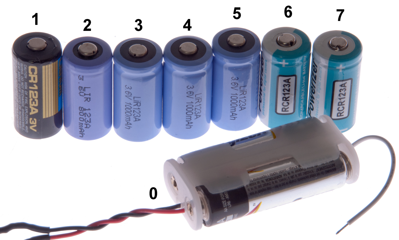
Battery Resistance
I've added this because battery resistance has a huge impact on motor operation (when battery power is used).
No.
Type
Label
Volts
R
(milliOhms)
RPM
RE-140SA-2270
0
Primary
2 ea. Energizer E91
3.0
390
11,400
1
"
Panasonic CR123A
3.04
201
12,700
2
Rechargeable
LIR 123A 3.60 600 mAh
3.71
163
14,600
3
"
LiR123A 3.6V 1000mAh
3.01
355
2400
4
"
LiR123A 3.6V 1000mAh 3.98
9910
0
5
"
LiR123A 3.6V 1000mAh 3.99
8560
0
6
"
Powerizer RCR123A
4.15
72
7
"
Powerizer RCR123A 4.16
78
> 16,000
Shaft Diameter
It seems clear that the shaft diameter depends on the maximum torque rating of the motor.
The flywheels were made to accommodate diameters of: 1.0, 2.0. 3.17, 4.0 and 5.0mm.
A table/plot of Kv v. shaft diameter should have a monotonic shape (linear or square law?). So one way to estimate Kv & Ki is to measure the shaft diameter (assuming the motor designer knows what he's doing).

Videos
Back EMF
This can be demonstrated by connecting the motor to a DMM and the power supply in parallel.
Once the motor is up to speed the power supply is disconnected, leaving the DMM connected across the motor.
The back EMF starts out just slightly lower than the power supply voltage.
Kv (RPM/Volt)
Stall Torque
The stall torque constant is roughly 100 grams/Amp.
The flywheel pulley grove has a circumference of 6.000", diameter is (6/PI) 1.910", 4.851cm. dia, or 2.426 cm radius
So the stall torque constant (Ki) [force * radius/current] or about 243 g cm/Amp or 0.024 N m/amp
This is very close to the Ki value on the data sheet and derived from the Kv measurements of 0.02 Newton meters/amp.
Testing Unknown Motors
Shaft Size
(mm)
Body Size
dia x len (mm)
Electrical Data
RPM vs Voltage line
Kv, Ke
ID
2.3
27.5 x 38
y = 863.5x - 1091.3, R² = 0.9998
Kv= 863.5 RPM/V = 90.4 Rad/Sec VKe =1/Kv = 0.011059 Sec V/Rad = 0.011059 N m/Amp
Ki =11 mN m/Amp
added 11Volt point:
y = 842.36x - 989.86, R² = 0.9993
HC313MG-120
close but different
Related
DC Permanent Motors
Flywheels
Bicycle Science
References
Johnson Motors
Kysan Electronics p/n Search
Mabuchi
Links
PRC68, Alphanumeric Index of Web pages, Contact, Products for Sale