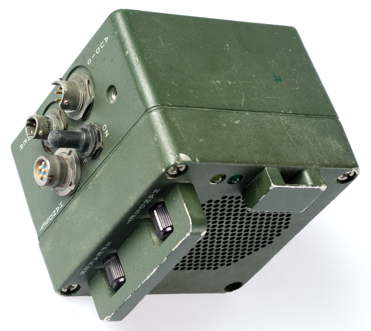
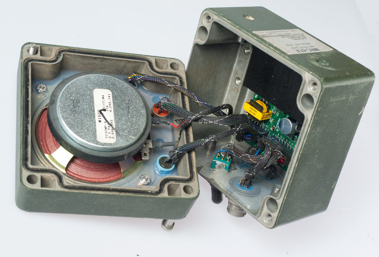
MRC-67A Amplifier-Speaker
© Brooke Clarke 2011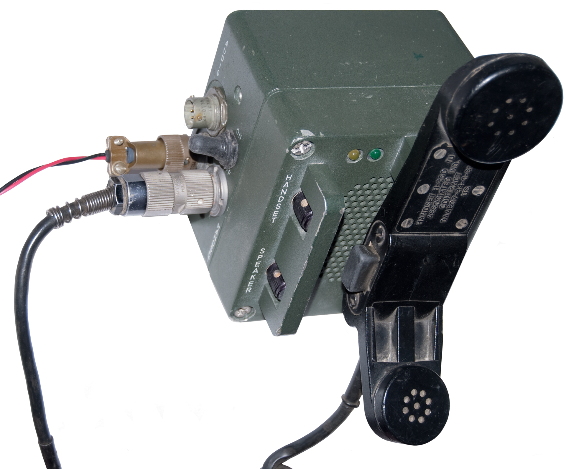
 |
 |
|
ON/OFFToggle switch
HANDSETU-229
type audio
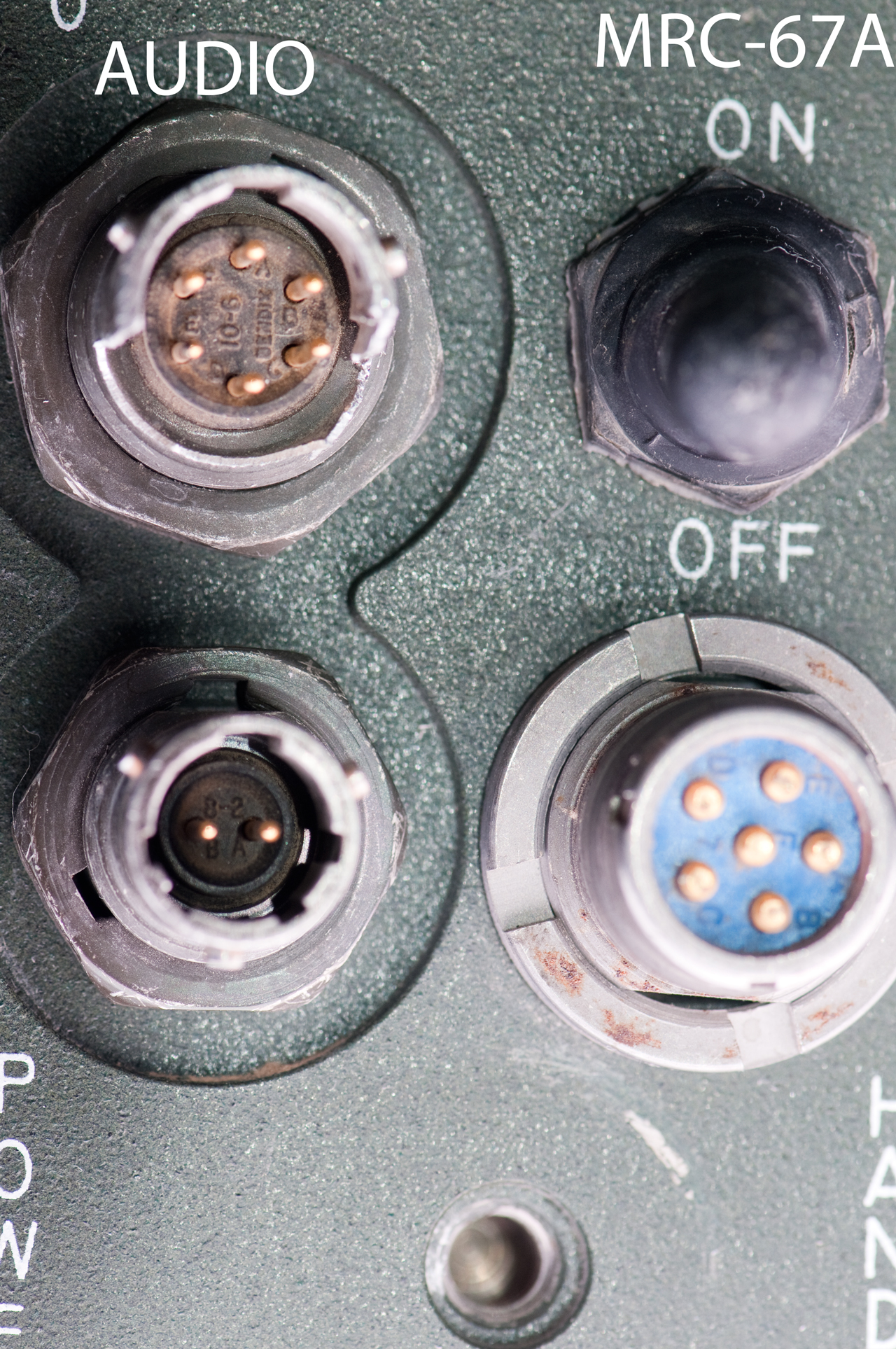
POWERChassis: 2 mail pin
Cable: MS3116 F8-2S A: +10 to 36VDC B: Gnd
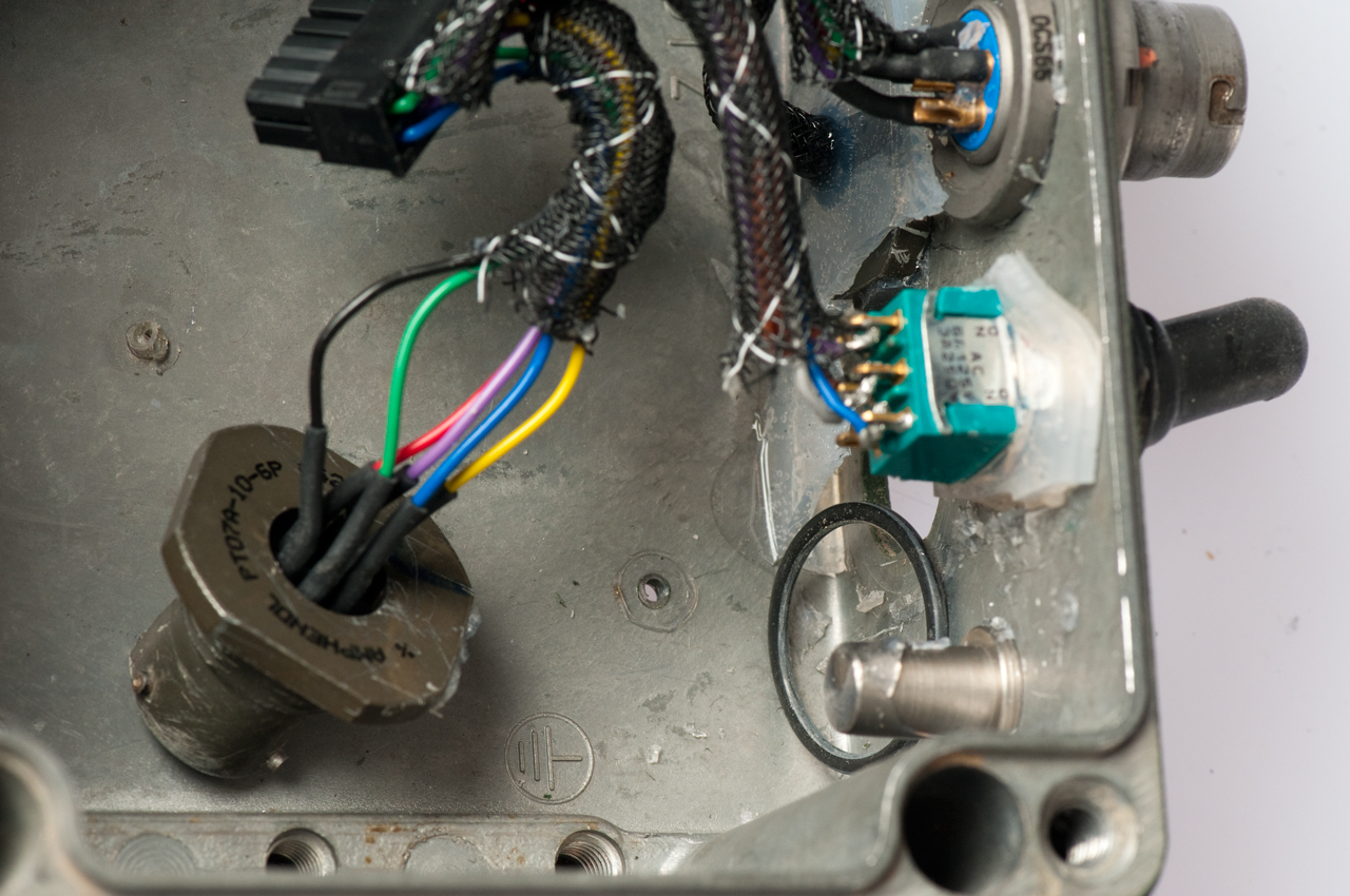
AUDIOChassis: MS3114 E10-6P
(PT07A-10-6P) Cable: MS3116 F10-6S
Handset VolumeTop knob
Speaker VolumeBottom knob
Green LEDDC Power good
Yellow LEDReceive Audio Present
|
 |
 |
| P1- |
1 |
3 |
5 |
7 |
9 |
11 |
2 |
4 |
6 |
8 |
10 |
12 |
| Red |
Vio |
Blu |
Grn |
Blu |
Blu |
Blk |
Yel |
Grn |
Yel |
Vio |
Viio |
|
| Speaker |
S |
S |
||||||||||
| Green LED | L |
L |
||||||||||
| Yellow LED | L |
L |
||||||||||
| Handset Vol | H |
H |
H |
|||||||||
| Speaker Vol | SV |
SV |
SV |
| P2- |
1 |
3 |
5 |
7 |
9 |
11 |
13 |
15 |
17 |
2 |
4 |
6 |
8 |
10 |
12 |
14 |
16 |
18 |
| Grn | Red |
Vio |
Grn |
Yel | Blu |
Blk |
Blk |
Brn |
Blu |
Vio |
Yel |
Gry |
Vio |
Org |
nc |
Red |
Red |
|
| On/Off | A2 |
A1 |
BC |
AC |
B2 |
|||||||||||||
| Handset (E, F: nc) |
A |
B |
D |
C | ||||||||||||||
| Power | B |
A |
||||||||||||||||
| Audio | A |
C | F |
B |
D |
E |
| A1:
Blu |
B1:
nc |
| AC:
Gry |
BC:
Brn |
| A2:
Vio |
B2:
Org |
Back to Brooke's PRC68, Products for Sale, Photo of Military Audio Accessories, U-229 Audio Accessories, Military Audio, Squad Radio, Military Information, Personal Home
page created Nov 18, 2011.