There have been a number of
audio connectors used on military and
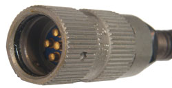
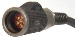
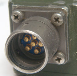
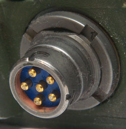
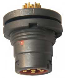
civilian equipment. The U-229 family is the current military
standard audio connector. There are 5 and 6 contact versions
of the connector.
This connector started out as just an audio connector since at the
time radios were all analog in nature. But with the advent
of digital circuitry this connector started handling digital data
in addition to the audio data. Note that data can be
transmitted over radio or wire line audio channels using tones in
the range 300 to 3000 Hz, called Audio Data in the
SINCGARS radios.
Note that I've been trying to figure out how this connector is
used for many years. My
Audio
Connectors page was started in 2000, the
U-229 Audio Accessories page was was
also started in 2000. The thumbnail photo
Military Audio Accessories page is from
2001. This page was done in 2004.
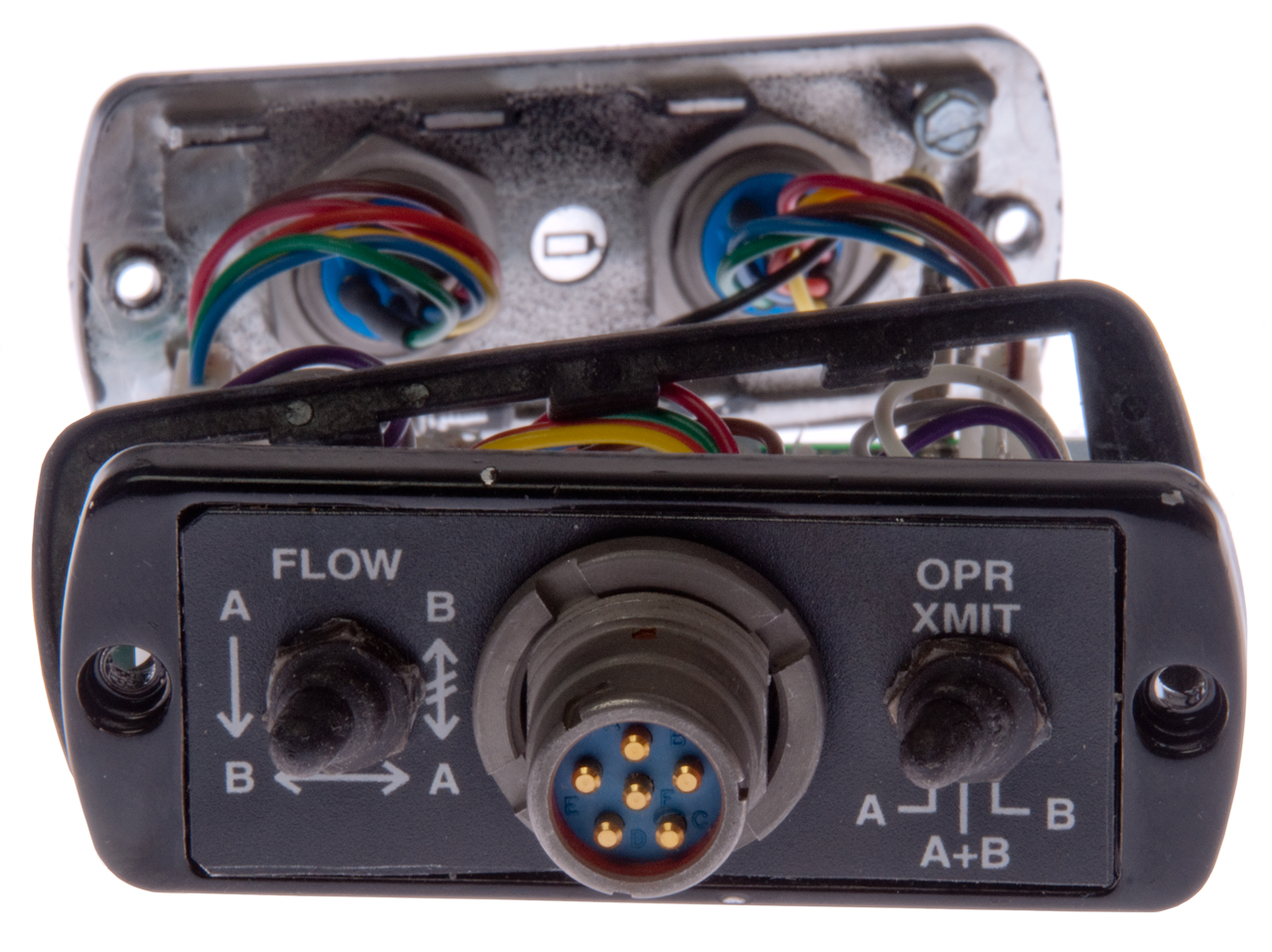
The different uses for the U-229 type connector needed to have
been designed with the idea that although they all used the same
mechanical connection, plugging in a device used for one task into
a jack for another should not cause damage to either. This
seems to be working, an impressive design.
The
SINCGARS,
and probably other radios, have a U-229 family connector marked
ADUIO/DATA.
When an audio accessory is connected, like the
H-250 handset, the above
AUDIO
pin assignments are active.
Note that the SINCGARS radio has two AUDIO connectors, one marked
AUDIO/FILL and the other marked AUDIO/DATA. So the digital
functions for Fill and Data are completely different
circuits. Audio can be used on either connector, but the
digital modes only work on the connector labeled AUDIO/DATA.
Analog
Analog data is like an FSK modem or FAX machine that uses audio
frequencies between 300 and 3000 Hz. The Tacfire and PSG-2/5
may use these tones. This method can be used with either HF
or VHF radios, depending on the baud rate and so is a popular way
to send low speed data. In the SINCGARS these are the AD2
(also called TF for TacFire) and AD1 modes.
Digital
Digital data is like form the UGC-74 teletype, a computer serial
port, etc. The upper speed limit for this type of data is 16
kb/s, which is the rate for the
KY-57
and the maximum rate for the SINCGARS radios. Baud rates
are:
RT-1439: 75, 150, 300, 600, 1200,
2400, 4800, 16000 and for the RT-1523 the rates are: 600, 1200,
2400, 4800, 16000 bps.
MIL-STD-188-114, 6V polar,
NRZ differential.
Definition: (Formerly "RS-449") An
EIA
standard
for a 37-pin or 9-pin
D-type
connector (functional- and mechanical characteristics), usually
used with
EIA-422
or
EIA-423
electrical specifications.
RS-422,
RS-423,
and RS-449 - A Compatible Improvement of RS-232-C.
Note that RS-422 is
differential, but can be directly connected to an unbalanced
RS-232 port and I expect that MIL-STD-188-114 works the same
way. So some interfaces use just one of the differential
lines. When it's an output the unused line is left floating,
and when an input the other line is grounded.
However when a data device is connected and the proper mode has
been selected the pins have new meanings as follows:
Data Connector Pin Functions
For a SINCGARS radio:
A = ground
B = MIL-STD-188-114 Digital Data out of Radio
C = PTT to key radio (ground for Talk) [this is a buss and any
device can ground it]
D = Analog Data Input for transmission or Digital Data Clock Out
E = Digital Data Mode Select - Gnd = Digital Data, Open = voice or
Analog data (handset leaves this pin open)
F = Analog Data Mode Select - (ground for digital data) or Digital
Data for Transmission input (handset leaves this pin open).
Possible Configurations (just a guess)
Mode
|
Data Rate Selector
|
Pin D
|
Pin E
|
Pin F
|
Voice1
|
na
|
Mike in
|
hi open
|
hi open
|
Analog
Data (Tones)
|
baud
rate < 16000
|
Tones
in
|
hi open
|
gnd
|
asynchronous
Digital
Data
|
baud
rate < 16000 |
n.c.
|
Gnd
|
Data In
|
| asynchronous
Digital
Data2 |
any
baud rate
|
n.c.
|
hi open
|
Data In
|
| synchronous
Digital
Data |
baud
rate 16000
|
Clock
Out
|
Gnd
|
Data In
|
I think that when a baud rate is selected, other than 16 kb, that
asynchronous data transfer is used. But when 16 kb is
selected the clock lines are needed.
Note
1 - Note that when both pins E and F are open
(high) the AUDIO/DATA connector on a SINCGARS radio is expecting
pin D to act as a mike input. If low level digital data is
fed into pin D there will be some strange modulation on the
output, but it will not be usable by a receiving station.
Note
2 - Another possible way to differentiate
between asynchronous and synchronous would be to leave pin E open.
If you know please
email me.
Since the
KY-57 would need
to interoperate with a SINCGARS radio in both voice and data
modes, I think it also responds to data on it's AUDIO connector
using the above format.
Typically a special cable will need to be made up, see TM
09726-13.
Since the
RT-1439
uses a separate connector just for retransmit I'm making a new
paragraph here for this function. When a U-229 type audio
connector is used for retransmit ground is on pin A, the audio out
from the radio is on pin B, PTT on pin C and audio in on pin D
just like a standard audio connector. The special signal
needed in addition is a squelch closed signal to drive the PTT on
the other radio (note PTT is a ground true signal so I called the
output signal squelch closed meaning not squelch open asserts
PTT). Pin E is used for the retransmission output on the
PRC-25,
PRC-77,
RT-246, RT-524, R-442 RETRANS with the
Mk-456 Retransmission Kit. The
SINCGARS RXMT connector also uses pin
E for the retransmission output and in addition uses pin F as an
A/D select (Analog pin open and Digital when grounded).
The
VRC-12 series radios may also use
AUDIO pin F for the retrans keying output.
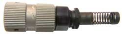
The most common problem is a dry
O-ring. This will make it difficult to mate and to
uncouple. I like Radio Shack Lube-Gel which is an oxygen
free Silicon grease (PTFE). There are other Silicon greases
that probably work the same, but the ones I've found locally cost
at least twice as much.
There is an O-ring lubricant sold for use on paint ball guns but
so far I have not been able to find out what it is, so can not
make a recommendation. I have the bottle in a ziploc bag in
the freezer to see what happens. After a few days it's still
a liquid. But no MSDS from the maker.
(NSN 5330-00-905-6032)
NAME: ITEM NAME O-RING
ADVN: CROSS-SECTIONAL HEIGHT 0.055 INCHES MINIMUM AND 0.061 INCHES MAXIMUM
ADYT: CENTER HOLE DIAMETER 0.605 INCHES MINIMUM AND 0.615 INCHES MAXIMUM
MATT: MATERIAL RUBBER CHLOROPRENE CLASS CR
This has been reported as being a metric 1.5 mm by 15.5 mm OD
Chloroprene (generic Neoprene).
A Buna-N version is available from McMaster Carr as p/n
9262K636
Cross Section
|
Center Hole
|
0.061 /
0.055
|
0.615 /
0.605
|
| 1.5 mm
= 0.059055" |
15.5 mm
= 0.610236 |
This looks good. I received the O-rings and they do work.