DAGR - Defense Advanced GPS Receiver
© Brooke Clarke 2008 - 2025
Background
Firmware Versions
GPS Signals
M-code
Crystal
Frequencies
Major Influences
DAGR (Polaris Guide)
GB-GRAM (Polaris Link)
docs
Capabilities
Classical PVT
Applications
Gun
Laying System (North Finding, Surveying)
Single
Receiver Method
Dual Receiver Method (Sub mil)
Dual Polaris
Azimuth Determination
DAGR & Polaris Az
Fire Support (Target Location,
Waypoint Determination)
Close Air Support (CAS-9 Line Brief)
Jammer Finder
Spoofing
Compass
Carrier Phase Data
Time
Differential Corrections
PLGR-II
Comparing PLGRII and DAGR
External Antenna Jacks
Data Transfer
DAGR, Polaris, PLGR
Reprogramming (Polaris SW Versions)
Polaris
Variants
Batteries
Four AA Batteries
Memory Backup Battery
J4 External DC Power
(DAGR & Polaris)
External Power Consumption vs. Input Voltage
Stock Turck PKG3
DAGR Specific
J1 & J2 D-Sub 15
Pin Connectors
Have
Quick & 1 PPS J2 Cable
DAGR/PLGR to DAGR/PLGR Cable
Mystery
Cable
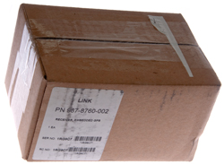
Shipping
Container
Applications
Azimuth
Determination
Averaging
Zero Baseline Testing Single Receiver
Method
Survey Equipment
Outdoor Zero Base Line Walk
Compass
Time Display
Operating Modes
Cold Start
Maps & Images
SV Messages
Mounting
DAGR
Personnel Case
Antenna
Trimble 28367-40
Trimble 17572-100
AeroAntenna
Technology AT575
AeroAntenna
Technology AT2775-42 with the
Choke Ring
Sensor Systems S67-1575-58
Lucent
KS24019L112C
RA-1 Magnetic Mount Remote Antenna
Power Splitter
Breakout Box
DC Power
SeaLINK
USB-RS422
Scratches on LCD Plastic
Rockwell Patents
Purchasing Polaris
Glossary
References
Links
Background
The first military use of the GPS
system was around 1990 in the desert wars where the SLGR (
Trimpack) was used. It started
out as a three channel L1 CA code (i.e. civilian) receiver.
A few years later the
PLGR was
introduced. It's a 5 channel L1 receiver that can be used
with both the CA and P (when keyed) codes.
The diagram below shows the evolution of the Rockwell GPS
receivers. I think the PLGR III was an experimental receiver
that was not fielded or if it was only in small numbers.
 |
The MicroDAGR (pdf)
and it's civilian version the MicroGuide (pdf)
were introduced in 2013.
These appear to be Android operating system based much
smaller versions of the DAGR.
BUT . . . they do not have the 15 pin VGA type
connectors and instead use some USB or other
connector. This is a problem because of interfacing
to other hardware devices. USB-C came out in 2014 (Wiki) so
I doubt it's part of the Micro/DAGR and that's also a
problem.
|
Firmware Versions
as of July 2010
DAGR
3.1
984-2461-
|
DAGR
3.2
984-3006-
|
MWO
Release Date
|
Features Added or
Improvements
|
-009
|
-na
|
Oct 2004
|
Original DAGR 3.1
|
-011
|
-001
|
11-5820-1172-20-1
31 Mar 2005
|
Original DAGR 3.2 w/minor
updates to 3.1
|
-012
|
-002
|
11-5820-1172-20-2
31 Jan 2007
|
Improved under canopy
reception, CAS function, better mapping, etc.
|
-015
|
-005
|
11-5820-1172-20-3
27 Mar 2008
|
Gun-Laying Azimuth
function, WMM2005 update, LRF
interface functions
|
-016
|
-006
|
11-5820-1172-20-4
30 Mar 2009
|
Improved multi-path
performance, bubber alerts, DAGR-to-DAGR transfer, low
battery warning, etc.
|
-017
|
-007
|
pending
|
Signal processing
enhancements for low-power signals, improved Mission
Planning in DAGR Map Toolkit, improved data transfer for
'hot start' of other SAASM devices, etc.
|
GPS Signals (Wiki)
I suspect that a Software Defined Radio type architecture is
used. This means that the DAGR/Polaris can receive the in
development L1C, L2C, L5 and M codes with just a firmware
upgrade. Also there are a number of GNSS (
Wiki)
signals that probably can also be received.
When the receiver is reprogrammed it probably will still have the
same number of channels but how they are allocated in frequency
and code is TBD.
Link Designation
|
Name
|
Freq (x10.23) MHz |
Code
|
Reference
|
L1
|
Everybody
|
1575.42
(154)
|
C/A
WAAS P(Y)
|
IS-GPS-200D |
L1C
|
Civilian
Quasi-Zenith
Satellite System |
"
|
BOC(1,1)
TMBOC
CNAV-2 |
IS-GPS-800 |
L1M
|
Military |
"
|
M MNAV |
|
L2
|
Military
|
1227.60
(120)
|
P(Y) |
IS-GPS-200D |
L2C
|
Civilian |
"
|
CM CL
CNAV
|
IS-GPS-200D |
L2M
|
Military
|
"
|
M MNAV
|
|
L3
|
Nuclear
Detonation
Detection System
(Wiki)
|
1381.05
(135)
|
|
|
L4
|
being
studied for Iono correction
|
1379.913
(1214/9=134.888)
|
|
|
L5
|
Safety
of Life |
1176.45
(115)
|
I5
Q5
CNAV
|
IS-GPS-705 |
WAAS (
Wiki)
is for the Americas. The military WAGE (
Wiki)
is either global or area specific. There are similar
augmentation systems for other parts of the world.
The L5 signal allows for ionospheric corrections making aircraft
(and all other) systems much more accurate. Another aspect
of Safety of Life is signal integrity allowing the user to know he
has a good solution and when he doesn't. WAGE is only
available after the GPS crypto key is loaded.
M-Code
It turns out that Russia has jammers with a range of maybe 10
miles in Ukraine that prevent the classical military GPS
systems (L1, L2, C/A, P(Y)) from working. The M-code may
be a solution.
The DAGR is not capable of receiving the M-code (
Wiki)
signals. M-code does away with the fixed data frame format now
used and instead uses data packets. This allows much more
freedom in how the space vehicles are configured. I'm
guessing that over a hot spot, like Ukraine today, the signals
coming from the SVs will be very different that what's transmitted
over the CONUS. It turns out that the whole infrastructure
that supports GPS will need to be upgraded to support
M-code. As of Aug 2024 this has not been completed, maybe by
the end of 2025?
Overview of the GPS M Code Signal (
betz_overview.pdf)
-
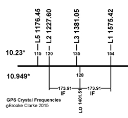
Crystal Frequencies
The 10.23 MHz crystal and it's harmonics are shown in the
table above and in the illustration below. Also shown
below is the 128th harmonic of the 10.949297 MHz
crystal used in the Rockwell Collins GPS receivers (see Polaris Link below) in order to
center the LO between L1 and L2 so that a single LO can be
used for both frequencies with the same IF frequency of 173.91
MHz.
Major Influences
- When GPS was a proposal it would have failed to be funded if
it were not for the Nuclear Detonation Detection System (Wiki).
(First launch 1978 Feb 22, so the proposal stage may have been
in the mid 1960s?)
- Prior to the 1 September 1983 shoot down of KAL007 (Wiki:
President Ronald Reagan ordered the U.S.
military to open their Global Positioning System
(GPS) to civilian use.) GPS was a secret and stealth
technology. That's to say the signal on the Earth's
surface is below thermal noise, so if you don't know where it
is and how to demodulate it, you will not know it's there.
- Wiki: In the 1990s, the FAA started
pressuring the military to turn off SA permanently and it was
on 1 May 2000.
- The Safety of Life L5 signal, see above, is driven by the
FAA.
DAGR (Polaris Guide)
Note case is a green color.
The DAGR is the current (accepted 2004, current 2008)
receiver. It's a 12 satellite L1 (12 chan) & L2 (12
chan) receiver that can be crypto keyed.
It has many improvements when compared to the
PLGR.
As of Oct 2008 there are two versions.
AN/PSN-13 p/n 822–1873–001
Firmware: 984-2461-011
and
AN/PSN-13A p/n 822-1873-002
The "A" version has a faster serial port to allow the use of USB
to serial converters and it has another 1 PPS output.
Firmware: 984-3006-001
The DAGR is
procured
under specification SS-M/V-600A, SS-M/V-600B, SS-M/V-600C as of
2007.
Polaris Guide HNV-1660
SPS Standard Positioning Service (SPS marked)
Note case is gray.

|
PSN-13A DAGR
Precision Positioning Service (PPS not marked)
Note case is green.

|
Menu\System\About\Enter
(HWver)\Enter as seen when Function Set is Basic.
"Start Reprogrammer"
is not an option here.

Also see Applications & Jammer Finder
|
PSN-13A DAGR front removed (6 screws)
This receiver does not power up at all. DOA
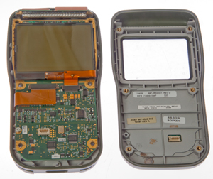
|
Menu\System\About\Enter (HWver)\Enter as
seen when Function Set is Advanced
-or-
Menu\System\About\Enter (HWver)\<dn arrow (SWver)\Enter
as seen when Function Set is Advanced
"Start Reprogrammer"
is an option here.

|
PSN-13A DAGR Top PCB open (1 screw)
Notice two antennas since L1 & L2.

|
|
PSN-13A Back Inside
two antennas at top backed by combiner & RF amp has
single coax to mother board. Other coax is from
external ant.
Components on flex circuit are power supply filtering.

|
PSN-13A Motherboard bottom
RF processing under metal top shields, Lowest metal shield
is marked ARM.
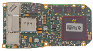
Near the lower left corner of the big black chip there's a
Honeywell HMC1052 2-axis Hall bridge magnetic sensor.
|
PSN-13A Motherboard top
Small white socket is for front panel keyboard.
 |
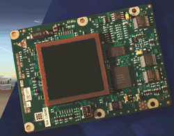
GB-GRAM (Polaris Link)
GB-GRAM
|
In addition to the handheld DAGR there is a
12 Channel printed circuit board version called the Ground
Based - GPS Receiver Application Module (GB-GRAM).
Note
a
Ground
Based
application
will
have
velocity, acceleration and jerk values much less than
those encountered in air and space craft and a GPS can
exclude the higher values making for a better
solution. More importantly GPS receivers
rated for air or space usage have more ITAR controls on
their distribution.
The military DAGR and GB-GRAM are CCI items that can not
be sold to civilians, but the Polaris Guide is the
civilian version and the Polaris Link is the civilian
version of the GB-GRAM.
|
Polaris Link
p/n: 987-8760-002
New In Box (NIB)
|
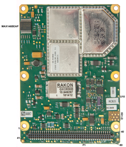
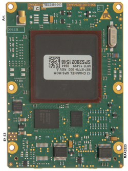
Polaris Link p/n: 987-8760-002
|
Polaris Link p/n: 987-8760-002
Single antenna connector since L1 only
|
|
The Polaris Link 12 Channel SPS (Standard Positioning Service)
board uses a Rakon 10.949297 MHz unit oscillator.
Documents
Spec 963-3036-101.pdf
Performance Specification for the Rockwell Collins, Inc. (RCI)
PolarisTM Link GPS Receiver 4 May 2007
Appendix D contains the pin out for the 80 pin
connector.
Polaris Link ICD 963-0792-102A.pdf
Interface Control Document for the Rockwell Collins, Inc.
(RCI) Polaris™ Link 24 September 2007
5230809425DesignersGuide.pdf
Polaris™ Link Designer’s Guide The Embedded GPS Solution
for Surface Applications 2007
Capabilities
Classical PVT
The classical military uses for GPS are Position (including
waypoints and Routes), Velocity and Time (PVT) and the DAGR has
all the capability of the
PLGR in this
regard. But in addition it can do more.
Applications
While trying to see what was in the Applications menu of the
Polaris SPS it jumped into Jammer Finder mode.
That was because after a cold start the Function Set is "Basic".
In order to get access to all the Applications you need to
change the Function Set to Advanced:
Menu \ Menu \ System \ Select Function Set \ Advanced.
Gun Laying System, Civilian: Azimuth
Determination
This is listed first since it's the feature that I'm most
interested in. Wiki says: "Gun laying is a set of
actions to align the axis of a gun
barrel so that it points in the required direction."
Since both bearing and distance between the two locations is
calculated this can be used as a surveying
method.
GLS will shortly be called Azimuth Determination for both the
DAGR and Polaris. This way it's OK for the Polaris to have
Azimuth Determination.
Real Time Kinematic (Wiki: RTK)
is the surveying term for a GPS receiver that tracks while it is
being moved. But in the surveying application there's a
radio link from the base station to the rover and the actual
position of the rover is known. The North Finding system
does not need to know the actual position of either point.
6181274
Satellite navigation receiver for precise relative positioning
in real time, MIT, Jan 30, 2001, 342/357.04 ; 342/357.08 - is a
similar patent but includes a radio link for code and carrier
phase corrections. The next generation Rockwell GPS
receiver may have RTK capability, but it takes more channels
since L1 and L2 must be on separate channels.
Single Receiver Method
Using a single DAGR with a survey grade GPS antenna
attached to the top of a pole over a stake and then moving it to
another stake you can determine the bearing and distance between
the stakes. This would allow surveying using a single
DAGR. Accuracy of 3 mils (1 mil at 1 km = 1 meter, in
NATO countries it's 1/6400 of a circle). 3 MILs is about
10 arc minutes of angle. Note that the SIN(3 MIL) * base
line length is an estimate of the error in the length part of
the measurement. In 100 feet that's about 3.5 inches
radius.
The method used is covered in patent 5999123 and involves carrier phase
tracking rather than differential corrections. That's how
they get such good accuracy. Rockwell has a number of
patents relating to the detection of carrier phase cycle slip
and precision carrier phase tracking methods which would help in
this application. For example excluding some satellites
from the beginning if they have carrier phase characteristics
that make cycle slip hard to detect.
The accuracy can be improved by minimizing the time of the
measurement because many of the error sources change at a slow
rate.
The accuracy can be improved by using a long base line.
The above two accuracy improvements work against each
other. The longer the base line the more time it takes to
move the receiver.
See zero baseline test results below for the
Polaris Guide civilian receiver.
5999123 Time-relative
positioning for static applications, Rockwell
International , Dec 7, 1999, 342/357.08
This is a method based on
tracking the carrier phase as a single receiver is moved from
one stake to another. The path between stakes does not
need to be along a straight line, but the view to all the
satellites being tracked must not be blocked. i.e. it
does not work near buildings.
| 5021792 |
System
for determining direction or attitude using GPS
satellite signals |
Jun 4, 1991 |
| 5266958 |
Direction
indicating
apparatus and method |
Nov 30, 1993 |
| Kit, Azimuth Determination Single DAGR
Receiver 987-6279-002 (NSN N/A) |
- The AD single receiver kit is used in the
calculation of the azimuth
- Installation mount, pole clamp for installation
mount, antenna, antenna cable and bag are included
|
Dual Receiver
Method (Sub Mil)
The Master/rover is programmed. The Slave/base GPS
control panel does not need to be operated.
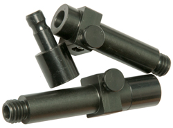
2022 April - The antenna/pole adapter so far is hiding from
me. It's the missing part in order to do the dual
receiver method in the field.
|

The requires a couple of Antenna/Pole Adapters
NSN: 5985-01-527-3372
p/n: 987-6315-001
The large thread at the bottom center of the RA-1 is NOT a
standard tripod 1/4-20 thread but is instead a
10-32. This makes it a problem to mount the RA-1
on a survey range pole, hence the above adapter. Let me
know where to get the adapter. |
Using AT-575 survey antennas
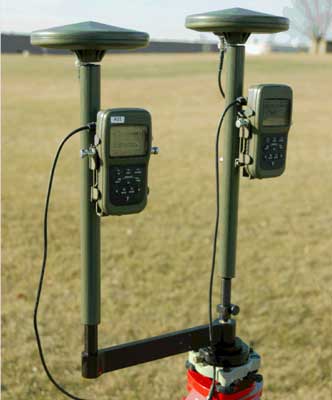 |
First generation system used AT-575
antennas.
now using RA-1 antennas
From TM 11-5820-1172-13 pdf page 435

|
Kit, Sub-MIL Azimuth Determination (AD)
Dual DAGR Receiver 987-6280-002
(NSN 5985-01-549-7219)
- The sub-mil AD accessory kit is used to increase
accuracy over the AD method of calculating the
azimuth
- Antennas, antenna cables, quick disconnect
DAGR-to-DAGR cable and case is included
|
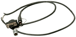
Note the cable shown is a single piece,
not a quick disconnect.
|
DAGR-to-Survey Antenna Cable (9.5 inches
with TNC connector) 987-5015-002 (NSN 5995-01-549-8449)
- For use with survey antenna (013- 1962-040)
- TNC plug (M) and right angle SMA plug (M)
- 9.5 inches
|
|
DAGR-to-Survey Antenna Cable (19 inches
with TNC connector) 987-5015-003 (NSN TBA)
- For use with survey antenna (013- 1962-040)
- TNC plug (M) and right angle SMA plug (M)
- 19 inches
|
|
Quick Disconnect Cable Socket
988-7042-002
NSN 5995-01-549-8447
- The DAGR/DAGR/PLGR cable provides for connection
between two DAGRs or between a DAGR and a PLGR
- 15-pin D-sub plug (F)
- 4-pin circular socket (F)
- 20 inches
- Transfer data includes: setup, waypoints, routes,
alerts, time, satellite data, position data and maps
- Intended use with azimuth determination system
(987-6280- 002)
|
|
Quick Disconnect Cable Plug
988-7043-002
NSN 5995-01-549-8451
CAGE: 13499
Mfr. 47Q1 0948
- The DAGR/DAGR/PLGR cable provides for connection
between two DAGRs or between a DAGR and a PLGR
- 15-pin D-sub plug (F)
- 4-pin circular plug (M)
- 40 inches
- Transfer data includes: setup, waypoints, routes,
alerts, time, satellite data, position data and maps
- Intended use with azimuth determination system
(987-6280- 002)
Belden
9927 (0.209", 5.31mm OD)
4-contact Lemo type
|
 |

|
DB-15
|
J1
|
J2
|
Lemo
|
2
|
S_Mux
|
1PPS_IN_RTN |
1
|
|
|
|
2
|
14
|
COM3_XMT |
COM1_XMT |
3
|
15
|
COM3_RCV |
COM1_RCV |
4
|
This wiring seems odd. I was expecting
DB-15 pin 3 (GND) not the 1PPS return DB-15 pin
2. Maybe that was a problem with this
cable?
|
|
Seco 5111-00 Quick Disconnect GPS Prism
Pole Adapter
|
|
This provides about the same accuracy as the AG8 gyroscope + Theodolite
(or Wild ARK-1
gyro) system but is much more rugged, smaller, lighter and less
expensive than the fragile AG8. But the AG8 does work in
underground locations where there is no GPS signal so probably
the gyro based systems are still being used for some
applications.
In the dual receiver method you specify a walk time with the two
receivers next to each other and cabled together so they can do
a precision time sync. After you have moved the rover to
the out post and the walk time expires both receivers make and
record a single measurement at the same instant. Then when
the rover GPS is brought back to the master GPS and they are
cabled together, an L1 carrier phase calculation is made
to determine the difference between the master and rover
locations. The improvement comes about because both
measurements are made at the same time. In the single
receiver method there is a time difference between the
measurements.
Accuracy in the 0.5 mil area or around 1 arc minute of angle.
The slave receiver is left on the starting tripod and the master
receiver is walked to the remote stake and stays there,
accumulating data, until the preset walk time expires.
Then the master is returned to the base location and reconnected
to the slave, where the computations are done to determine the
remote stake distance and bearing.
During the walk between stakes a clear view of the sky must be
maintained but the walk does not need to be in a straight line.
Breaking lock with a satellite degrades the result and if less
than 4 satellites it will fail the procedure.
Antennas for Azimuth Determination
They say survey grade external antenna(s) is (are) required for
both methods.
The first possible reason for the survey grade antennas is that
when a lesser antenna, like the RA-1 is
used multipath during the walk causes one or more satellites to
break lock making the method non operational. Survey grade
GPS antennas typically have choke rings below the antenna to
prevent multipath, but you could mount the RA-1 (or maybe the
DAGR/Polaris) over a ground plane to achieve the same
result. The two (AT-575, AT-575 on SECO pole) antennas
shown in the photo at left do NOT have choke rings.
A second possible reason is that Maybe the reason
has to do with keeping the antenna up above the person carrying
it during the walk. But that can be done using a pole and
GPS mounting bracket.
In the manual illustration they show two of the RA-1 antennas
being used, but the older photo shows a couple of AT-575 survey
type antennas.
Dual
Polaris Azimuth Determination
Menu \ Menu \ Applications \ Az Determination
A list of way points appears, just select the first one then
press ENTER to get to the setup screen.
At this point if a data cable is connecting two Polaris
receivers both screens show that Dual Receiver mode has
started.
The walk time started at 35 seconds.
Polaris Azimuth Determination pages
To move between these pages you can use the up/down arrow
or the Page/Quit keys.
The default units can be changed by pressing Enter and then
selecting the sub-menu item to change the units.
I think the pages shown as Fig 10 through Fig 14 are the same
for single or dual receiver modes.
Note the default units for everything are not what I'd like
to see, so you might want to change them before making a
measurement. Although I was able to change them after
the test was complete, but you may want to change them first
so that you can see if the results make any sense as you go.
Dual Polaris GPS Azimuth Determination
Fig 10

|
|
Fig 11
 |
|
Fig 12
 |
|
Fig 13
 |
|
Fig 14
 |
|
First steps in Dual Polaris receiver Azimuth Determination.
The key thing is how many satellites are in view. So
choosing the time of day to make the determination is
important.
Fig 1

|
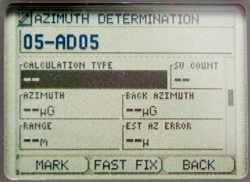
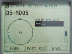
My Polaris shows:
Azimuth Determination
01-AD01
Status:
Tracking: 2 of 10
Use [Enter] to continue
Last Modified:
--
New Polaris shows:
Azimuth Determination
in progress
Do Not Move
the Receiver (i.e. this is the base receiver)
[Quit] to abort calculation
|
Fig 2
 |
My Polaris shows
Azimuth Determination
01-AD01
Status:
Tracking: 4 of 9
Use [Enter] to continue
Last Modified:
-- |
Fig 3
|
|
Fig 4
 |
My (rover) Polaris. The rover is in
control of the survey.
The base Polaris just sits there.
|
DAGR & Polaris Az
It turns out that they work together to determine the azimuth
and distance between two stakes. This first test was
done with an external antenna on each receiver sitting on a
window sill facing South and the data cable left connected
between the DAGR and Polaris throughout the test.
Fig 1
Polaris at left is rover. Base unit is linked.
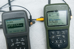 |
Fig 2
Use [Enter} upon Reaching Point 2
 |
Fig 3
Reconnect Receivers to Complete Calculation.
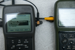 |
Fig 4
Results of calculation.
0.01m should be 0.00 meters since the antenna was not
moved. So a 1 cm error.
 |
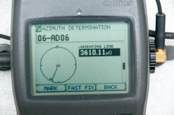
Fig 5
Orienting Line
This is a random number since there was no antenna
movement.
 |
|
Triple Receiver Method?
This is NOT supported on any DAGR as far as I know, but may be
on some systems, like on ships.
5021792 System for determining
direction or attitude using GPS satellite signals
This is a system that uses three
GPS receivers and three antennas.
Maybe a future enhancement on the dual receiver method, i.e. 3
Receiver method
The antennas are used:
First in a straight line
Second two of them are interchanged
Third one of them is moved away from the line by the distance
between the remaining two.
| 3766556 |
CHANNEL
SWITCHING
PHASE - for canceling IF non linearities
|
Oct 1973 |
| 4719469 |
Direction-determining
system - two fast switched antennas and interferometry
|
Jan 12, 1988 |
| 4845502 |
Direction
finding
method and apparatus - two antennas on rotating
platform are combined in balanced mixer
|
Jul 4, 1989 |
| 4881080 |
Apparatus
for
and a method of determining compass headings, Navy -
uses two antennas, ant switch and one GPS receiver
|
Nov 14, 1989 |
Fire Support (DAGR: Target
Location, Polaris: Waypoint determination)
The Polaris Guide WayPoint Determination application appears to
be the same as the DAGR Fire Support application.
This was also supported with the PLGR. By using a
compatible Laser Range
Finder cabled to the DAGR (or manual input of range,
bearing and elevation angle to the target) you can get the
coordinates of a target. This requires that the Laser
Range Finder sends at least the magnetic bearing and distance to
the target and better is the addition the elevation angle.
So far I haven't found LRFs on the open
market that have a range of more than about 1 km whereas the
military LRFs may be good for 10 km. The Vector binoculars
that include Laser Range Finding, Magnetic Compass, elevation
angle inclinometer and RS-232 data cost over $10,000 on the used
market. There are only a very few Laser Range Finders with
RS-232 output.
An alternate way to get target location would involve taking
multiple sightings from a different locations (maybe even from a
moving vehicle) where you only know magnetic bearing and
elevation angle. Then triangulate the readings. Note
by using more than two sightings averaging can be used to
improve the precision of the target location. The DAGR
does support multiple sightings of the same target.
There have been some tragic accidents when the soldier operating
the DAGR called for fire support and instead of giving the
target coordinates gave his own coordinates.
6064942
Enhanced precision forward observation system and Method,
Rockwell Collins, May 16, 2000, 701/213 ; 342/118;
342/357.01; 342/357.06; 342/357.08; 434/1; 701/207 - employs
multiple measurements to reduce the CEP
| 5736960 |
Atomic
clock
augmented global positioning system receivers and
global positioning system incorporating same |
Apr 7, 1998 |
| 5739786 |
GPS
transfer initialization system |
Apr 14, 1998 |
| 5757316 |
Attitude
determination
utilizing an inertial measurement unit and a plurality
of satellite transmitters |
May 26, 1998 |
Low cost astronomical orientation
sensors are available that can tell you the magnetic
bearing and elevation angle to any target. For example the
Clestron
SkyScout or Mead mySKY.
Vector 21
|
Vector
|
Function
|
DAGR
|
1
|
Gnd
|
3
|
Gnd
|
2
|
Trig
|
na
|
|
3
|
Trig
|
|
|
5
|
Data
|
14
|
Tx
|
7
|
Data
|
15
|
Rx
|
RS-232 9600 8N1
Data Format:
Zdddddd[CS]<CR>
Z: d: dist, a:Az, e: Elev;
C: Compass err, R: Range err, M: Main board err
|
Vector 21 Binocular Interface Cable
w/Remote Firing Button
NSN: 6150-01-5657-440
p/n: 234-300-38V-0001
p/n: 300-38V-0001-00
was: CA/F-2.5-05R
CAGE: 0UW80
Ashbury VECTOR 21 15 Pin Remote Fire
DAGR/PLGR Cable
Connectors:
Vector:
Fischer
WSO 1031 A012-41+
DAGR J2: DB-15f
|
Vector
IV
|
|
|
 |
|
|
There are civilian LRFs made for
golf and sporting applications with ranges up to about 1 km,
most are a few hundred yards. But there are also
civilian LRFs that have long ranges. Very few have data
output that can couple to the DAGR/Polaris Guide.
Note: The data format is not NMEA (
Wiki),
but a proprietary Leica format.
Vector 21 -
Ashbury
International, p/n: CA/F-2.5-05R - Vector 21 to
PLGR/DAGR Interface Cable w/Remote Firing Switch (
photo),
Tact3-S Tripod "For use with devices equipped with a magnetic
compass."
Leica Vector IV
Litton Mark VII - 7.3 x 18 day optics, 4 x 50 image
intensifier, Nd:YAG laser, eye-safe 1.57
micron
Riegl LASERTAPE FG21 - up
to 2500 meters
The military LRFs typically have a max range of about 10 km.
AN/GVS-5 (MX-9838) Nd:YAG 1.06
micron) hand held fielded 1980 - Class 4 Non-Eye Safe, only
usable in daytime
AN/PVS-6 Mini Eyesafe Laser Infrared Observation
Set
(MELIOS), only usable in daytime
MLR 30 - 20 km range, 1.064 microns
MLR 40 - 20 km range, 1.54 microns
LH30 - 80 m to 20 km
LH40C - erbium:glass laser, 1.54 microns, built in compass
& inclinometer
Leica Geosystems ZVBA
Brashear LP MLRF 100 - 1.54 microns, mounts on personal
weapons
AN/PEQ-21B Common Laser Range Finder (CLRF) - similar in
magnification and field of view to the M-22 binoculars, built
in compass & inclinometer, GPS interface
AN/AAS-37
AN/AAS-38 Nite Hawk
LRM 2500 CI
- 2500 m, built in compass & inclinometer
LRB 25,000 25
km - 1.54 micron eye safe,
YouTube:
ACE3 MicroDAGR and
Vector21 Tutorial | ArmA 3 - while intended for a video
game I think the instructions also apply to the real Vector 2
and DAGR.
Close Air Support (CAS-9 Line Brief)
This is a DAGR only application. The Search Grid
application in the Polaris Guide is very different.
Needless to say calling for CAS must be done correctly to
avoid fratricide.
See Ref 14.
The 9 Line items are:
1. Initial Point (IP),
2. Heading IP to Target,
3. Distance IP to Target,
4. Target Elevation,
5. Target Description,
6. Target Location (MGRS or ...),
7. Type of Mark,
8. Location of Friendlies,
9. Egress (Relative to Target).
Jammer Finder
While trying to see what was in the Applications menu of the
Polaris SPS it jumped into Jammer Finder mode.
That was because after a cold start the Function Set is
"Basic".
In order to get access to all the Applications you need to
change the Function Set to Advanced:
Menu \ Menu \ System \ Select Function Set \ Advanced.

|
I'm guessing that this was
because there were three Wi-Fi routers very close.
Tried outside and still get Jammer
Finder?
|
|
|
Polaris Guide Applications Menu when in
Advanced Function mode

|
Advanced Function Set Applications on
Polaris Guide:
WP Calculation (same as DAGR Fire Support)
Jammer Finder
Az Determination (same as DAGR Gun Laying)
Search Grid (mowing the lawn between two way points)
|
DAGR Applications Menu when in Advanced
Function mode
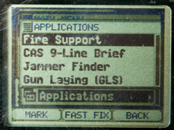
|
Advanced Function Set Applications on
DAGR:
Fire Support (LADS
Army.mil)
CAS 9-Line Brief (Close Air Support, Wiki,
Program
Pacer Speak)
Jammer Finder
Gun Laying (Azimuth Determination) |
|
Advanced Function Set "About" on Polaris
Guide
Menu\System\About\Enter (HWver)\Enter as seen when
Function Set is Advanced
-or-
Menu\System\About\Enter (HWver)\<dn arrow
(SWver)\Enter as seen when Function Set is Advanced |
Spoofing
Spoofing is very different than jamming (Wiki).
Jamming, when effective, prevents the authorized user from
making use of the signal. Spoofing sends false signals
to the authorized user, which in the case of GPS will cause
the location and/or time to be wrong.
GPSJAM.org
- Ukraine with date turned off, so when you look.
World Map.
HackRF - HackRF One
- Docs
-
eBay search term: "Portapack H2 Mayhem Firmware" - Saymlove
Electronic Store -
PortaPack
-
SV Message
Carrier Phase Data
The DAGR supports carrier phase data output. This is the
method used by surveyors to get very high levels of
precision. To use the carrier phase data for surveying you
need to convert it into RINEX format and then use post processing
software to remove the integer ambiguity. RINEX conversion
software is not currently available (Oct 2008). Also it's
not clear if the Polaris Guide (civilian DAGR) supports carrier
phase on just L1 or on both frequencies.
Time
Frequency hopping radios need the current date and time accurate
to less than a second. The Polaris supports both Have Quick
(
Wiki) and
SINCGARS time formats.
Differential
Corrections
There used to be GPS receivers on the coastlines of waterways,
operated by the US Coast Guard, transmitting differential
corrections (Wiki)
to improve the accuracy of GPS of ships in or near ports.
These were long wave transmissions. The long wave
transmissions had a range on the order of 100 miles so only
applied to a local area. Another way to get the same
correction data was to have a specialized GPS receiver, like the
Ashtech Z12,
that not only can receive and use the L2 phase information
without knowing the crypto key for the L2 data, but also
generates correction data that can be broadcast using UHF
radios. One name for this is Real Time Kinematic (Wiki).
CDDIS
disseminate Broadcast Corrections for GNSS satellite orbits and
clocks in real-time in RTCMv3 format -
Post processing is used in surveying GPS to combine the digital
data recorded in the field with data on the actual GPS satellite
orbit data (not the predicted ephemeris data used in GPS
receivers) to determine the precise location of the GPS
antenna. This can result in data accurate in the millimeter
region.
I have not seen any mention of post processing in the manuals for
military GPS receivers. I suspect that the Rockwell binary
control protocol has a provision to do this, but so far have not
seen a copy of the commands. If you have a copy please
let me know.
Another way to get differential corrections is the Wide Area
Augmentation System (Wiki:
WAAS)
which should provide 25 feet accuracy for aircraft.
Garmin
2018 says it gives <3 meters, but currently (2022) they
do not talk about it. This is a satellite based system and not
anywhere near as accurate as systems where the corrections are
generated close to the GPS receiver using them.
PLGR-II
The PLGR-II was made for Special
Operations and some foreign governments (Australia,
UK?). It's a 12 channel L1& L2 receiver.
Montgomery
Design page about PLGR and PLGR II. "MDI worked with
Rockwell to adjust the surfaces of their prototype unit,
minimizing the potential for cavitation."
There are three versions:
SofTouch Standard green case - 1 meter underwater
Dive Capable black case - 10 meters operational (20 meters
survive)
Deep Dive gray case - 24 meters operational (36 meters survive)
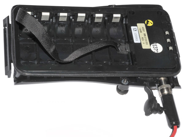
Batteries
The removable battery tray can hold up to 8 AA cells. There
is a menu item for Alkaline or Lithium cells and for 6 or 8 cells.
(not sure which 6 to install for this option).
The memory battery is the 3.6 V 1/2 AA just like the DAGR.
After installing the batteries the SV Status page shown ALM AGE:
99 DAYS. But after more than a half hour later the ALM AGE:
drops to 1 DAY when four satellites are being tracked.
Memory Battery: Interstate Batteries
LIT2830
UPC: 656489 043368 - SAFT LS14250 3.6 Volt Li-SOCl
2
Comparing PLGRII
and DAGR
Once any GPS receiver has locked onto one satellite it can then
download the almanac data for all the other
satellites. That takes a little less than 15
minutes. Once that's happened the ALM AGE: will change from
some number between 2 and 99 days to 1 day. Prior to taking
these two photos the almanac was made current. The key
difference of the PLGRII is it's heavier and the buttons take much
more force to activate, probably both of those differences are
because this PLGRII can be operated down 10 meters and stored at a
much greater depth in water. The DAGR is only specified for
1 meter of water.
The PLGRII uses an 8 AA cell battery tray with the option of a 6
AA tray that has an external DC power connector. If you
don't have the optional 6 AA battery tray you can not use external
DC power.
Outdoors

|
Indoors

|
PLGRII External Antenna Jack
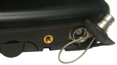
The PLGRII external antenna connector is a waterproof
type. I expect the mating connector looks just like
the plug shown here. It's 6.17 mm (0.243")
O.D. Now to find out what it is.
This is the same O.D. as the 75 Ohm SMB, but should be 50
Ohms and the SMB male pin does not look to be in the
correct location.
|
DAGR External Antenna Jack
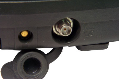
The DAGR External antenna connector is the very common SMA
(3mm). Notice the nut on the external antenna cable
will be recessed into the pocket so you can not tighten it
with your fingers. There is a "Spinner" available
for this. It's a plastic wheel with fingers that
snap onto the hex nut.
|
PLGR
II Rechargeable battery Holder p/n 988-3123-003
made in 2002
holds 6 each AA size rechargeable batteries (the stock
battery holder carries 8 AA cells).
There is also an external power connector that will NOT
accept the standard PLGR power plug.

|
External
Power
Connector on PLGR II 6 cell battery holder
The connector appears to have the correct threads for the
stock PLGR power plug, BUT the plastic case is too small
to clear the threaded nut on the plug.
A laptop power plug will not work again because the
plastic is too close to the socket centerline.
It appears to be a design defect. If you know of a
power plug that works let me
know about it.
|
They both work about the same outdoors and indoors.
Menus
Holding down MENU gets you to the Quick Menu page. Use the
arrow keys to select and ENTER to goto that menu.
When in Quick Menu is PAGE is pressed the menus rotate as:
Quick Menu -> Operations Menu -> Setup Menu -> Data Menu
-> WPT/RTE Menu -> Calc Menu -> SV Menu -> Apps Menu
-> Quick Menu
Setup Menu
Use the arrow keys to select and ENTER to goto that menu.
RECEIVER
|
UNITS
|
NAV-SETUP
|
INIT
|
USR-DTM
|
I/O |
USR-COORD
|
SUBMODE |
KOI-18
|
|
KEYPAD
|
P
|
INIT POS/PRECISE
CLEAR
Lat
Lon
EL:
GS:
TRK:
The Title line POS or PRECISE can be selected and CLEAR activated.
Lat, Lon, Elevation, Ground Speed and Track can be initialized.
Pressing PAGE brings up the crypto key input in either
Hex or
Decimal notation.
KOI-18
Paper Tape Load
Select LOAD then pull tape.
LOAD
QUIT
Data Menu
Use the arrow keys to select and ENTER to goto that menu.
NAV
|
RCVRSTAT
|
POS
|
SVSTAT
|
RCVD SCRNS
|
TSS
|
POS RPT
|
ZERO/CLR
|
|
P
|
Help Menu
Note: to get to the Help
menu from the Quick Menu instead of pressing down arrow four
times just press up arrow once.
HELP
TAB:[A]
If an arrow key is pressed the focus will jump down into the
lower list.
If ENTER is pressed, then up or down arrow the letter after TAB:
will increment or decrement and the list will change being
centered on the new letter.
Once the correct TAB:Letter has been selected press any arrow
key to move the focus to the center of the list of topics.
Now press ENTER and notice that to the left of the current topic
an Up and Dn arrows appear. Now pressing UP or DN arrows
scrolls the list.
Waypoint Route Menu
Use the arrow keys to select and ENTER to goto that menu.
WPTNEW
|
RTEEDIT
|
WPTEDIT
|
RTECOPY
|
WPTCOPY
|
RTECLEAR
|
WPTCLEAR
|
ALERTS
|
WPTSTATS
|
|
WPTGROUPS
|
P
|
Receiver Hardware Status
Pressing PAGE:
RCVR HW STATUS -> RCVR SW STATUS -> CONFIG STATUS ->
RCVR HW STATUS
Data Transfer
Send To:[com-a] [com-b]
Type:[all] rcvr setup] [targets] [submode
setup] [user coord] [time] [user dtms]
[units setup] [sv data] [mission data] [all]
SEND
QUIT
Operations Menu
Use the arrow keys to select and ENTER to goto that menu.
WPTNAV
|
RTENAV
|
MARK/MOB
|
SKIPWPT
|
UNITS SEL
|
REVRTE
|
TRACK-MODE
|
HSF-CFG
|
GOTO
|
SEND
|
SUBMODE SEL
|
P
|
SUBMODE SEL
Submodes: 1 Foot, 2 Gnd Veh, 3 Para HAHO, 4 Aircraaft, 5 Maritime,
6 Dive, 7 Survey, 8 Spare
ACTIVATE
QUIT
HSF-CFG History File Configuration
Calculate Menu
Use the arrow keys to select and ENTER to goto that menu.
DISTANCE
|
LRF
|
FROM
|
|
BEARING
|
|
INTERSECT
|
|
|
P
|
LRF
Requires stored Laser Range Finder data
Applications Menu
Use the arrow keys to select and ENTER to goto that menu.
JAMMER FINDER
|
|
SELFTEST
|
|
TARGETING
|
|
|
P
|
JAMMER FINDER
SELFTEST
Targeting Menu
NEW
|
VIEW
|
CLEAR
|
WPCOPY
|
DEFINE
|
SETUP
|
Space Vehicle Menu
SVSTAT
|
SV SELECT/DESEL
|
DOP-CALC
|
SV-SCHED
|
Tailored Screen Sequence Page
It depends on the selected submode.
Data Transfer
This is supported between two GPS receivers of the same type
like a DAGR-DAGR data transfer, or between different GPS
receivers, either PLGR, DAGR or Polaris.
DAGR, Polaris, PLGR
Left to Right:
DAGR (Internal Antenna),
Polaris (w/antenna on window sill),
PLGR (w/antenna on window sill)
All running on external power.
|
 |
This is done using a DB-15f Serial
Data Cable. This cable will fit the DAGR, PLGR and
Polaris.
The transfers between like units and between the DAGR and PLGR
in either direction are factory supported. But the
transfers between the Polaris to or from the DAGR/PLGR are not
documented.
There are three scenarios where data transfer is used: Setup,
Gun Laying (Az determination) and Reprogramming.
Setup
The idea is to transfer as much of the information from the
source GPS to the target. This is mainly used to bypass
the 15 minute delay in loading a complete ephemeris. But also
includes things like the settings and display unit preferences.
DAGR -> DAGR (factory)
|
PLGR -> PLGR (factory)
|
Polaris -> Polaris
(factory)
|
DAGR -> PLGR (factory,
works)
|
PLGR -> DAGR (factory)
|
Polaris -> DAGR
|
DAGR -> Polaris (works)
|
PLGR -> Polaris
|
Polaris -> PLGR
|
Reprogramming (Polaris SW
Versions)
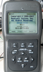
My Polaris is an older version
Copyright 1989 - 2007
Hardware Ver: 0111
Software Ver:811-0573-001 |
"Like New" condition unit on loan
Copyright 1989 - 2009
Hardware Ver: 0111
Software Ver: 811-3093-001 |
Differences
|
Ext DC supply from push-on
 |
Ext DC power from screw-in
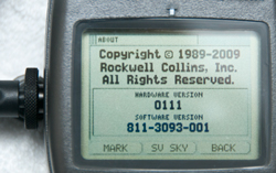 |
they are the same Hardware version, which
is a requirement to reprogram the software.
|
 |
 |
In the Communications menu the 2007 SW
supports PPS, HQ and SINCGARS.
The 2009 SW only has PPS.
|
Reprogramming the 2009 version Polaris GPS back to the 2007
version
Fig 1 Start Reprogramming
 |
Fig 2 Start Reprogramming
 |
Fig 3 WARNING!
Reprogramming will
clear all data on
the other receiver
 |
Fig 4 NOTE!
Reprogramming Software Application
Types Are Different
[enter] to continue
[quit] to cancel
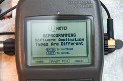 |
Fig 5 Reprogramming In Progress
No Other Functions Available Until Complete
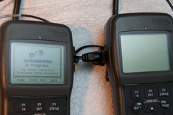 |
Fig 6 System\About: now 2007 Version
 |
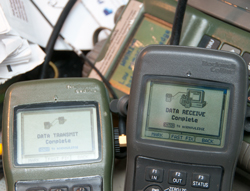
Fig 7 Data Transmit/Receive in
Progress
To save the 15 minutes waiting for the new
software to acquire all the satellite data & to get
into English units a data transfer was done.
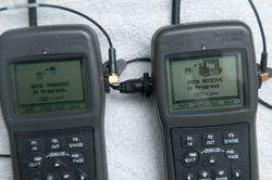 |
Fig 8 Data Transmit/Receive Complete
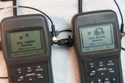 |
Fig 9 AC power supply:
NSN: 6130-01-521-3157
13499ASSY987-4975-001 Rev F
Mfr: 47VQ1
1252
--------------------
Input: 100 - 240 VAC
Output: 12VDC 1.0A
 |
Polaris
Data Sheet (Rockwell
Collins)
Variants
Software
Department of Commerce
- Standard
- Situation Data Advospr (SDA) based upon DoC Standard
Department of State ITAR Controlled - CAT XV(F)
- Military Use
- Military Use Link (MUL) CoC Standard + Call for Fire, CAS 9
Line, Gun/Mortar Laying
- Situation Data Advisor (SDA) based upon Military Use Link
Ref. Situational
Awareness and Communication Experiment for Military Operations
in Urban Terrain: Experiment 1, Elizabeth Redden &
Cynthia L. Blackwell, Oct 2001. - mainly about Situational
Awareness (SA). Note that the DAGR and Polaris support both
raster images and vector images that can be used to enhance SA.
Ref. Moving
Map and Situational Awareness Capabilities of the DAGR, Gary
L Bachman, Rockwell Collins, 2005 - makes use of "ArcMap™
component of the Commercial Joint Mapping Toolkit (C/JMTK)" and
the GPS Map Toolkit (GMT) for a PC. only supports maps
having a WGS-84 horizontal datum. "Waypoints and other
non-map features comply with MIL-STD-2525 DoD Interface Standard,
Common Warfighting Symbology [2] and FM 101-5-1 Operational Terms
and Graphics [3]. Map feature symbology (associated with vector
maps) complies with MIL-DTL-89045 [4]."
Batteries
Main battery pack plus memory hold -up.
In TM 11-5820-1172-13, pdf page 520, Table 22-1 Common Battery
Types:
Table 22-1. Common Battery Types
| NOMENCLATURE |
Size
|
Voltage
|
RECHARGEABLE |
BATTERY USE |
BATTERY
TYPE |
APPROXIMATE
BATTERY
LIFE * |
STORAGE
TEMPERATURE ** |
| Lithium |
AA
|
1.5
|
No |
Main |
L-91 |
16.5 hours |
–40 to +60 °C
(–40 to +140 °F) |
| Alkaline |
AA
|
1.5
|
No |
Main |
W-B-101 |
11.5 hours |
–18 to +55 °C
(0 to +131 °F) |
| Nickel Metal Hydride |
AA
|
1.5
|
Yes |
Main |
NH–15 |
10 hours |
–40 to +50 °C
(–40 to +122 °F) |
Lithium
|
½ AA |
3.6
|
No |
Memory |
LS14250 |
8 months |
–60 to +70 °C
(–76 to +158 °F) |
* The approximate battery life values are based on
continuous mode of operation and operating at room temperature.
Battery life will vary depending on temperature and what mode of
operation the DAGR is using. Colder temperatures may decrease
battery life. Operating modes other than continuous may increase
battery life.
** These storage temperatures are for the individual batteries
only. The DAGR, stored with primary and/or memory batteries
installed, is limited to the operating temperature range in
Paragraph 15.2.2, unless further restricted by these storage
temperatures
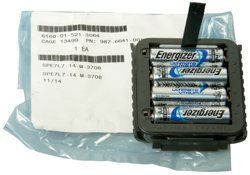
Four AA Main Batteries
 |
All the printing is inside the battery
compartment.
Notice that the title: Receiver, Hand Held SPS
The "SPS" means Standard Positioning Service" i.e. the
legal to own civilian model.
SPS also appears on the lower right of the front panel.
When installing the AA batteries it's best to lower them
into the battery holder while holding level. If you
tip the battery and try to install it one end then the
other it's a very tight fit.
Don't forget to put the removing strap unter the cells.
Energizer
L-91 Lithium 1.5 V Primary NSN: 6135-01-333-6101 -
these have more capacity and work at temperatures where
Alkaline batteries fail. the L-91 also has a shelf
life of 20 years.
|
Memory Backup Battery
2022 Feb: warning about low memory battery. Installed new
one. Be careful when ordering the battery since some of
them come with leads welded on each end. It takes some filing to
remove the nub.
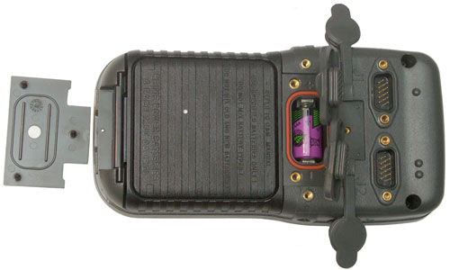 |
The White dot on the memory battery cover
and the white dot on the main battery cover are the
vents. Single bump connector is J1, two bump
connector is J2.
Memory battery is 1/2 AA size 3.6 Volt Lithium.
Radio Shack 23-026 aka:
3B26TC, 3B33TC, 3B955TC, 29045, ER3S, G3 ER3STC, LS3,
LS14250 NSN: 6135-01-435-4921
TO4, TL-5101, TL-5101/S, TL5111/S, TL5112, TL5112/S,
TL5151
Note there is also a 3.0 Volt Lithium 1/2 AA size battery,
but it probably will not last as long.
There is no pull strap for this battery and it's a very
tight fit, so a small screwdriver may be needed to get it
out.
|
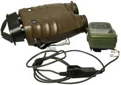
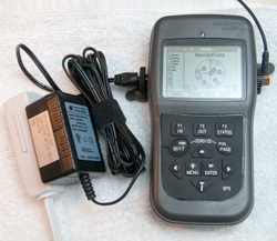
J4 External DC Power
Polaris (DAGR) GPS receiver with
Turck PKG3M6S90S Cable
 |
This is the connector the Rockwell
documents recommend as of 2008 BUT, it is very difficult
to install and remove because the stock nut is almost
completely surrounded by the recessed pocket so you need
strong fingernails to install it.
External Power Consumption vs. Input Voltage
12 Volts seems to be the lowest power drain, hence the
voltage on the AC supply.
Volts
|
ma
|
mw
|
<7.x
|
0
|
0
|
8
|
129
|
1032
|
10
|
99
|
990
|
15
|
65
|
975
|
20
|
52
|
1040
|
25
|
44
|
1100
|
The DAGR/Polaris switching power supply draws about the
same power independent of fluctuations of the input
voltage. |
Polaris (DAGR) with DAGR
specific Cable

|
This cable was made for the DAGR, but may
be very expensive. The problem is there are really
two nuts, the one shown above is on the cable and
another nut is installed over it. The outer nut is
not tight against the internal nut so after it's been
snugged when you wiggle the outer nut you feel
slop. That may be because someone who has
not been properly trained over tightened it and that
may lead to a broken plastic case.
The other problem is that the nut makes a rattling noise
when the receiver is shaken. That might consume a
lot of someone's time trying to find where the rattle
was located. Note the outer nut is in reality a
finger driven socket wrench.
Plastic finger driven socket wrenches are used on more
modern cables.
J4-1 = Ground = Brown
J4-3 = Positive = Blue
J4-4 = no connection (or ?)
|
|
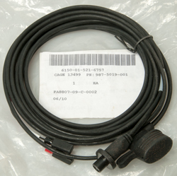
DAGR External Power Cable Fused (5m)
987-5019-001
NSN: 6150-01-521-6757 |
- Use to connect a DAGR to an external power source
- DAGR connection can be secured to prevent
inadvertent removal
- Lugs installed on source end of cable
- 3-pin power plug (F)
- In-line fuse holder installed
- 5 meters
|
 |
DAGR External Power Cable, Fused (2 m)
987-5009-001
NSN: 6150-01-521-6755 |
- The DAGR-to-external power cable, fused provides for
connection between a DAGR and an external power source
- 3-pin power plug (F)
- 2 meters
|
|
DAGR Cigarette Lighter Power Cable
987-5008-001
NSN: 6150-01-521-2548 |
- The cigarette lighter power adapter provides for
connection between a DAGR and a cigarette lighter
- DAGR connection can be secured to prevent
inadvertent removal
- 3-pin power plug (F)
- In-line fuse protected
- Coiled cord
|
|
DAGR AC Power Adapter
987-4975-001
NSN: 6130-01-521-3157 |
- Connects the DAGR to an AC power source
- Compatible voltage: 110 to 240 volts
- Two prong, North American style plug
- 3-pin power plug (F)
- Operates on 50 or 60 Hz
- 3 meter cord
Input: 100 - 240 VAC
Output: 12VDC 1.0A
|
|
Cold Weather Battery Pack
987-7050-001
NSN: 6130-01-530-4652 |
- Cold Weather Battery Pack (CWBP) is an external
power supply designed for extended use with a DAGR
when batteries are the only practical means for power
- 8-AA cells (consisting of two 987- 6641-001), 1.5
VDC
- 3-pin power plug (F) on pendant cable
- 1 amp fuse
- CWBP requires two spare prime power battery
magazines (987-6641-001) that are sold separately
Designed to be used with Molle M16A2 Magazine Pouch or
NSN 8465-01-465-2092 Molle II Mag Pouch
The cable is in my opinion too short and the external
power connector would benefit from a right angle. Normally
cold weather battery systems have a long cord so that
the battery pack can be placed inside clothes to keep it
warm. (RPG-7 sight).
You need the separate Cold Weather Battery Pack Cable to
use this adapter, see below.
Note this adapter takes two battery holders and they are
wired in series so it supplies 12 Volts to the DAGR.
If the same batteries were used for all three battery
holders the run time would be tripled. But I don't
see a use for that.
It's very awkward to stack the adapter next to the DAGR.
|
|
Cold Weather Battery Pack Cable
426-0227-010
NSN: 5995-01-533-3421 |
- Cold Weather Battery Pack (CWBP) cable is an
external power cable that interfaces the CWBP to the
DAGR
- 3-pin power plug (F): P1
- 3-pin power plug (M): P2
- 2 meters
|
|
Molle II
Pouch,Magazine, M16A2,
Double (30 Rounds)
NSN 8465-01-465-2092
DAAK60-97-D-9302
|
Mag Pouch used to hold the Cold Weather
Battery Pack (CWBP)
|

|
Spare Prime Power Battery Magazine 987-6641-001
NSN: 6135-01-521-3064 |
- Spare prime power battery magazine is
interchangeable with the prime power magazine that is
provided with the DAGR
- 4-AA cells, 1.5 VDC
note: Using Energizer L91 Lithium primary battery since it
has many advantages.
------------------------
These are probably on the market because the rubber gasket
is old and cracking.
This makes it difficult to install or remove the battery
magazine.
The same thing happens to the gasket in the U-229
audio connector.
Replacement O-Ring is 3/32" x 3" -149 size - a dab of
Silicon grease will prevent this. Also getting a
material, like Viton (Wiki),
that does not biodegrade is a good idea. (rubber
biodegrades in air or water.)
|
|
Adapter Cable PLGR External Power
987-5020-001
NSN: 6150-01-521-3510 |
- The cable adapter PLGR external power provides for
connection between a DAGR and a PLGR external power
cable
- Right angle plug (M) - ?
- 3-pin DAGR power plug (F)
- 8 inches
|
J1 & J2 D-Sub 15 Pin Connectors
The fifteen contact connector on the DAGR is the same one that's
on the
PLGR. Most of the
functionally is the same as for the PLGR. For example the PC
cable is the same for either the PLGR or DAGR. They are not
exactly the same, but are very close. The 15 pin High
Density D-Sub connector is the same one used for PC video monitors
(Wiki:
VGA connector).
The computer monitor cable has DB-15m connectors on both ends and
so will not mate to the DB-15m connectors on the DAGR. But,
an HD15 video extension cable has an HD15F connector on one
end. You can just cut off the HD15M connector to have a
ready made cable.
Another problem is that when the DAGR is in the mount there is not
much room behind it, so a normal DB-15 connector hood will stick
out the back too far to allow the mount to be used. If you
know of a hood that can be installed to the left or right
let me know. The Right Angle
type connectors have the angle going up or down which is good, but
there still isn't a commercial sideways shell.
Note PLGR J2 is very close to DAGR J2 (although there are small
differences). See the DAGR manual J1: Tbl20-1, J2 Tbl20-2.
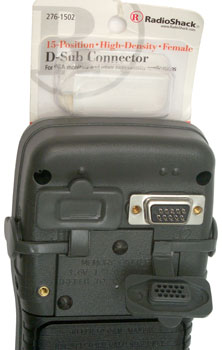
The Radio Shack 276-1502 is a "15 Position High Density Female
D-Sub connector with solder cups that fits the DAGR and PLGR
allowing you to make up your own cables. Jameco 164823
is much lower in cost.
Note one bump over J1 and two bumps over J2. Seems strange
that they didn't put three bumps over J3 and four bumps over J4.
In the photo it's not easy to see all three rows of pins on the
connector, but they are very clear on the bottom of the dust boot.
The PLGR used a fifteen contact size D-Sub shell to hold the
external antenna coax. That seemed a waste of space and the
DAGR uses a recessed SMA RF connector and two fifteen contact
interface connectors. Each of which can be setup to do
various things.
J1 Functions
- COM3 with mandatory hardware handshake (RTS/CTS)
- RS-232 2-way coms (300 to 76800 baud), or
- Time Fill for SINCGARS
- 1 PPS In & Out
- Key Fill on DAGR
- Accept Differential GPS (DGPS) corrections
- Output NMEA sentences
- Input Laser Range Finder (Mk VII or Other)(data format TBD)
J2 Functions
- COM1 RS-232 2-way coms (no handshake)
- COM2 (no handshake)
- RS-422 2-way coms, or
- RS-232 2-way coms
- 300 to 115200 baud
- Time Fill for Have Quick
- 1 PPS In & Out
- Map Up or Down Loading to PC
- Remote On - Off switch (details TBD, probably open or gound
connection)
- COM1 or COM2 can Accept Differential GPS (DGPS) corrections
- COM1 or COM2 can output NMEA sentences
- COM1 or COM2 can input Laser Range Finder (Mk VII or
Other)(data format TBD)
DAGR/PLGR J2 Pinout - 15 pins
Pin
|
Function
|
Characteristics
|
1
|
1 PPS Time Mark In
|
Input Z: 50 Ohm
Pulse width: 15us - .1s
Voltage WRT Gnd:
Logic 1: 2.5 - 5
Logic 0: 0.0 -0.8 |
2
|
1 PPS Time Mark In Return
|
Reference |
3
|
Ground
|
Reference
|
4
|
Serial Data Port Out RS-422
A
|
Voltage
(A WRT B)
Logic 1: +2 to +6
Logic 0: -6 to -2
Load: >= 100 Ohms
|
5
|
Serial Data Port Out RS-422
B
|
6
|
1 PPS Time Mark Out
|
Load: 50 Ohms
Pw: 20 us
Voltage WRT Gnd:
Logic 1: 3 to 5.0
Logic 0: 0 to 0.5
|
7
|
HAVE QUICK out
|
Voltage WRT Gnd
Logic 1: 300us @ +4.5 to +5.5
followed by 300us @ 0 to +0.5
Logic 0: 300us @ 0 to +0.5
followed by 300us @ +405 to +5.5
Sink/Source: <= 0.5 mA
Data Period: 600 +--2 us
|
8
|
Remote ON False
|
Power On: Ground
<=100 Ohms @ 0.5 mA
Power Off: Open
>= 50 k Ohms
|
9
|
Serial Data Port In RS-422 B |
Voltage
(A WRT B)
Logic 1: +0.2 to +6
Logic 0: -6 to -0.2
Input Z: >= 200 Ohms
|
10
|
Serial Data Port In RS-422 A |
11
|
1 PPS Time Mark Out Return
|
Reference
|
12
|
External Programming Voltage
|
WRT Gnd: 12 +/-0.5
300 mA Max
|
13
|
Serial Data Port Buffer
Enable False
|
Jumper to Gnd
<= 1 Ohm @ 100 mA
|
14
|
Serial Data Port Out RS-232
|
Voltage WRT Gnd
Logic 0: +5 to +25
Logic 1: -5 to -25
Load >=3k Ohms // <=2500pF
|
15
|
Serial Data Port In RS-232
|
Voltage WRT Gnd
Logic 0: +3 to +25
Logic 1: -3 to -25
Load: >= 3k Ohms
|
Other references:
SS103190 & SS110990: HAVE QUICK
ICD-GPS-153: 1PPS, Remote Off, NMEA, RS-422,
TBD port Functions
DAGR/PLGR to/from DAGR/PLGR
data set loading (soon firmware cloning)
Reprogram DAGR firmware
Each COM port can be setup to
support:
Inputs: ICD-153, Local Area DGPS, NMEA
Outputs: ICD-153, NMEA

|
This screen is the same on the Polaris
and DAGR.
|
Have Quick & 1 PPS J2 Cable
This cable has the 1 PPS output on the BNC connector and the Have
Quick data on the wire pair. The 1 PPS can be used as the
trigger source for the scope and the have quick data then starts
at the trigger point. BUT, the
HP54501A
Scope can not display the seconds data because of
limitations in the window function. The problem is that
there's a preamble on the Have Quick data that's about 1/4 second
long and there's a 20:1 relationship between the main time base
speed and the fastest possible window speed.
I think a way around this is to use the SRS
DG535 as a delay generator
triggered from the 1 PPS on this cable and use it's output to
trigger the scope. Now the scope time base can be set to a
rate that will allow a number of samples to occur during each 600
micro second bit time. The plan is to have just the unit
seconds (and maybe part of the tens of seconds bits on the screen
and compare to a digital clock that turns over on the UTC second
edge. Unfortunately the DAGR/Polaris does NOT change it's seconds
time display on the UTC edge, but can be off by up to a second or
slightly more so you really don't know the time by just looking at
the display. Seeing the Have Quick data should show that
it's very accurate.
Shipping Container
Received in double box. This is the inner box with a very
cleaver cardboard fold, it's not shrink wrap, you can remove the
Polaris after unfolding.

In addition to the Polaris there was a two page packing slip.
Order placed 17 Oct 2008 received 14 Jan 2009, pretty close to 3
months.
No batteries or other paperwork is included with the unit.
This is the same box used to ship the DAGR.
Polaris Applications
2022 Feb - both the Polaris Guide and DAGR jump to Jammer
finder when the Applications menu is selected.
This is caused by being in the default Basic Function Set which
was the case since the receivers had not been used for a long
time and needed new batteries.
In order to get access to all the Applications
you need to change the Function Set to Advanced:
Menu \ Menu \ System \ Select Function Set \
Advanced.
Azimuth Determination, North Finding,
Survey Mode (mil speak: Gun Laying System)
Once in the AZ Determination page proceed as follows:
4AK = 4 Arrow Keys
- Press Menu and scroll to Create New, press Enter
- With the name highlighted, press Enter and 4AK select the
letters and numbers for you chosen name then 4AK to move to
SAVE and press enter.
- With the Walk Time highlighted press Enter, 4AK to set
between 1 and 180 seconds, then press Enter
- The display will ask you to press Enter to start the
process. (Prior to this the receiver should have been
in Continuous mode and locked on a number of satellites, but
if not then you will need to wait here). You can't
start until at least 4 satellites are being tracked, more is
much better because while you are walking you may loose some
and if the total number goes below 4 then you need to start
over.
- After you are stratified with the number of starting
satellites press Enter and the display will switch to the
walk time count.
- Walk to the second point and when in position press Enter
while holding the receiver still, it will take maybe 5 to 10
seconds to determine position 2. (takes about the walk time
again)
- When it's done press the down arrow to proceed.
- The data defaults to military units. Changing the
units in the main Menu does not effect this page, so 4AK
highlight each field press Enter, and select which units to
change, for example the bearing change to degrees and the
reference change to True, distance in Miles and feet, etc.
The first result window shows:
- Single Receiver Method (I think you need to connect a
second receiver in order for this to change, it's not a
menu choice)
- Azimuth: 62.29 deg True
- Back Azimuth: 242.29 deg True
- Range 47.02 Feet (0.01 feet is approximately 1/8 Inch!)
- Estimated Azimuth Error: +/- 000.49 deg.
- Press the down arrow to move to Point 1 Information
- 10 S 405008 East
-
37905 North
- 988 Ft MSL
- Press the down arrow to move to Point 2 Information
- 10 S 485021 East
- 443379
North
- 987 Ft MSL
Questions:
Is it better to carry the receiver so the LCD is vertical or
should the LCD be level? LCD level both for compass and GPS
reception.
Where inside the receiver is the internal antenna located? just
above the LCD.
Thoughts
Using a choke ring antenna would prevent multipath and so you
would not loose as many satellites. Once a satellite
looses lock it is removed from the solution because after it
relocks the cycle count is no longer valid.
17 Apr 2009
Zero Baseline Testing Single Receiver
Method
A way to test the accuracy of the azimuth determination system
is to NOT move the antenna. In this case the
roof top GPS antenna was used for
both the first and second positions. If the Azimuth
Determination procedure is run using a fixed antenna the result
should be a distance of zero with an arbitrary angle.
Things that can be varied are the
receiver mask angle.
Zero degrees
increases the number of SVs but also allows for more multipath
errors.
It’s also location
dependant.
The walk time is
controlled by making the setting greater than the actual time
and then pressing ENTER at the desired test time.
Note there is no display in the results that will tell
you the actual walk time so there’s a few seconds of error in
the estimate of the actual walk time.
The
number of SVs can be controlled to a small extent by when the
test is run since the satellite configuration changes with a 12
hour cycle.
The Walk Time input for the single receiver method just sets the
maximum allowed walk time, so it's best to just use two up arrow
presses to set it to 180 seconds. The actual second
measurement is made when you press ENTER at the second
location. My guess is that when the ENTER is pressed the
first time the DAGR starts logging carrier phase data.
When ENTER is pressed the second time the DAGR does the
calculations involving processing the logged data. So the
time it takes to process the data depends on the actual walk
time and is very close to half that time. For example if
the walk time was 2 minutes it will take 1 minute to process the
data.
Plot of Range error in Inches vs. Walk time in Seconds
What's not shown is the number of SVs used for the
solution. When the test is started there may be 8 to 10
SVs being tracked, but once any of them drop out they can not be
used in the solution so it's not uncommon to loose one or two
sattelites by the time the test has finished. Maybe
because of the change in number of SVs and/or different DOPs the
test results are not easy to nail down, but you can see there's
a definate relationship between walk time and
accuracy. A very rough rule of thumb might be:
Accuracy (Inches) = Walk Time
(Seconds) / 20
For example at 20 seconds the accuracy varies from 1/2 Inch to 2
Inches.
At 60 seconds it varies from slightly more than 2 Inches to
slightly more than 5 Inches.
The accuracy seems to get better than the rule of thumb when the
walk time exceeds 2 minutes. I'm not sure of this is real,
or not?
The problem with trying to use walk times near 180 seconds is
that the DAGR aborts the measurement at 180 seconds instead of
making a measurement. It's impossible to have a walk time
of more than about 175 seconds because the pressing of ENTER has
some time delay before it stops the test.
So for the single receiver method the possible angle accuracy
depends on how quickly you can move the DAGR while not blocking
any SVs. These are just calculations that have not yet
been tested.
If normal walking speed is three miles per hour (4 feet per
second), then after 180 seconds the baseline would be a little
under 800 feet (241 meters).
An
error of 9 inches in 792 feet is 0.054 deg (3.26 arc min) or
0.96 Mils.
If a running person traveled at 8 miles per hour (12 feet per
second) then at 180 seconds the angle would be 9/25344 or 0.0198
deg or 0.35 Mils.
If a car averaging 30 miles per hour moved the receiver and the
test lasted 2 minutes the expected accuracy might be 0.0054 deg
or 0.096 Mils.
Survey Equipment to support Single
Receiver Azimuth Determination
SECO makes a
number of poles used to support either GPS antennas or prisim
retro reflectors that are suitable for this application and have
some very handy features. Since minimuzing the walk time
is important a system where the antenna is just plugged in
rather than locted is important. Although SECO makes a
number of clamps to hold survey data collectors they don't have
anything that's DAGR specific so I'm going to try and modify one
of their plain pole clamps to allow the stock DAGR mounting
bracket to be attached. (13 April 2009)
Part of Azimuth Determination Setup
SECO Pole (see: Tripods:
Range Poles)
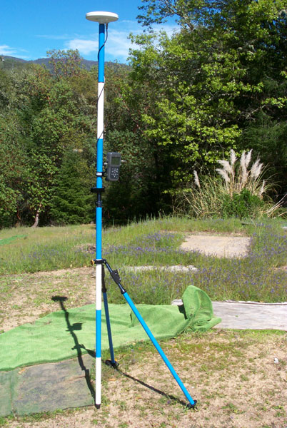
The Pole and bipod
are standard SECO (Survey Equipment Co) items. This is a
very modular system where all the pole sections have 5/8-11
female threads on both ends.
A friction clamp is holding the DAGR standard mount with a 10-32
screw and flat washer making the connection. The left
mounting hole in the DAGR mount is used so that the back
connector area is clear of the pole.
Just below the DAGR there is a circular bubble level (black
object to left of pole).
Just below the bubble level is a quick disconnect fitting.
The black pole is attached to the pole above and can be lifted
off the lower pole.
The lower pole is fitted with the bipod. The upper part of
both bipod legs has a lever actuated length adjustment to allow
easy plumbing of the pole.
Rather than spend a lot to get another of these pole setups, I
just got a male
quick connect pin with
a 5/8-11 female thread to put on top of my
existing
surveying tripod for the second location.
The pole plus bipod arrangement has an advantage over a tripod
in that the distance between the GPS antenna and the mark on the
ground is a fixed distance. That's not the case with a
tripod.
This setup breaks down to a much shorter length and fits into a
carry bag.
DOP Planning
Yesterday (17 Apr 09) there were 7 satellites being tracked but
after moving the receiver 33 paces away and returning to the
pole the error message was poor satellite geometry. So
some planning needs to be done before hand to chose a time when
the geometry is good. Trimble has a free program called
"Planning" to do this.
Trimble Planning Software
Downloads -
They also have a web page where you can get current GPS data.
GPS Data
Resources - Almanac files
Outdoor Zero Base Line Walk
21 Apr 2009 - Choose 11:45 to 12:05 window and tried two
walks.
The first for about 2 minutes resulted in a no solution, poor
DOP message.
I'm guessing that if I walk too
close to my house some sats are blocked and dropped and the
remaining sats don't have a good enough DOP. So to
access some locations the path may need to be curved to keep
clear of the house GPS shadow.
The second for about 1 minute resulted in a distance error of
about 4 inches.
28 Apr 2009- It's straight forward to modify the
987-5006-001 mount by adding SECO p/n: 103868-005 (
5198-052
or
5198-056)
and the associated 1/8 x 7/16 spring pin and 1/4-20x1/2 cap
screw. Then it plugs into the p/n 5198-052 Pole Clamp and
can be adjusted for tilt. You can just see the spring pin
below the quick release pin on the mount that mates with one of
the the small holes on the pole clamp. While the clamp was
designed for a range pole, it works fine on a shelf.

Averaging
Procedure
When displaying the current position press:
MENU - scroll to Select Op Mode - press ENTER - scroll to
Average - press ENTER - when a screen to Do NOT MOVE press
ENTER again. Note just below the longitude display the
seconds count will increment once per second until it gets to
32400 (1/2 a day or very close to one orbit of the GPS
constellation, the optimum time for an average).
Results
In good weather the difference between repeated averages that
are 32400 seconds long is 0.01 arc seconds on lat or long and
1 foot in elevation.
April 2015 DAGR with antenna on windowsill (poor view of sky):
Date
|
Lat (N)
|
Lon (W)
|
Elev (ft)
|
7 Apr 2015
|
39:11:24.30
|
123:09:50.57
|
na
|
7 Apr 2015
|
39:11:24:.32
|
123:09:50.57
|
924
|
8 Apr 2015
|
39:11:24.28
|
123:09:50.57
|
927
|
8 Apr 2015
|
39:11:24.31
|
123:09:50.52
|
927
|
9 Apr 2015
|
39:11:24.29
|
123:09:50.55
|
931
|
10 Apr 2015
|
39:11:24.29
|
123:09:50.54
|
933
|
11 Apr 2015
|
39:11:24.28
|
123:09:50.54
|
934
|
| 11 Apr 2015 |
39:11:24.33 |
123:09:50.49 |
916
|
| 12 Apr 2015 |
39:11:24.28 |
123:09:50.54 |
926
|
13 Apr 2015
|
39:11:24.29 |
123:09:50.53 |
926
|
| 13 Apr 2015 |
39:11:24.30 |
123:09:50.52 |
930 |
Compass
This is a 2D compass and so has major errors if the LCD face
is not perfectly level. There should have been a small
bubble level built into the receiver. You can set the
compass to display bearings referenced to either the magnetic
North pole or True Bearings based on the corrections in the
World Magnetic Model (Wiki,
Sensors)
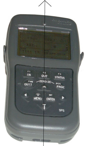
|
DAGR Polaris Guide GPS Receiver Compass Sights
There is a raised North arrow just above the center of
the display.
The down arrow is a raised button with a bearing
fudicial line on
the bottom that acts as the rear sight.
In the upper right of the display is the compass
bearing ddd.d.
I find even with the receiver on a table it's
difficult to set it to better
than a few tenths of a degree. The display in
the photo shows
000.2 deg
NOTE: The receiver needs to be held so that the
plane of the LCD is
horizontal. Any tip left, right, front or back
will introduce an error
in the compass reading. Best to use the compass
with the receiver
resting on a non ferrous table or in the mount (with
the mount horizontal).
I'm guessing this type of a calibration corrects for
hard iron (nearby magnets) as well as soft iron (metal
that distorts the Earth's magnetic field.)
That means that the calibration should be done as
close to how the magnetic compass will be used.
So, for example, you should not calibrate on a wood
table if you plan to use the compass while carrying a
rifle or other iron material. If it will be
mounted in a vehicle that vehicle should be driven in
a circle to do the calibration.
|
The DAGR/Polaris Guide has in built-in magnetic compass.
In addition there's a built in World Magnetic Model which
needs as inputs the current date, Lon, Lat and
Elevation. Since this is a GPS receiver that knows all
those inputs the local magnetic deviation is known and so you
can choose to have the compass display referenced to: Magnetic
North, True North or Grid.
Calibrate
It seems that you need to calibrate the compass just prior to
using it. This needs to be done away from metal objects.
MENU, MENU, Display Setup, ENTER, scroll to INTERNAL COMPASS,
ENTER, ENTER (highlights a field) scroll to ActiveDisabled and
use arrow keys to select ACTIVE, ENTER. Scroll down to Last
Calibrated, ENTER, scroll to Select Time Zone, ENTER, scroll
to your time zone, ENTER.
ENTER, scroll to CALIBRATE while holding receiver level press
ENTER and start rotating so the bearing rotates in a full
circle. Watch the display to see if you get a good cal.
Use
The Compass is in the Navigation Displays menu on the Position
page with one press of the scroll down arrow.
Once on the Present Position page press ENTER, then use the
arrow keys to highlight the compass display and select the
bearing reference (I like True which is something other
compass designs can not do).
The receiver needs to be kept level while using the compass,
like on a table or surveying post.
Power Consumption
In the DISPLAY SETUP compass menu there's an option for Enable
or Disable the compass. The manual says the receiver
draws more power when the compass is on than when it's
off. With external power I'm seeing a 2 ma current
savings when the compass is turned off (2 ma * 13 V is 26 mw)
Time Display
The DAGR / Polaris Guide POSition page, when scrolled down,
shows the current time and date. But, the displayed time
is often in error by 1 second. This is in my opinion a bug
in the Rockwell Collins firmware. All my other receivers
that display time have the seconds change at the UTC second
boundry. The Trimble Scoutmaster even displays the tenths
of a second correctly, see image below.
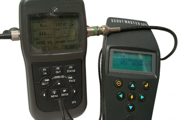
The Polaris
Guide (DAGR) is showing the time as 0852:00 but the time is
really 0852:01.0 as shown on the Trimble Scoutmaster to the
right.
An interisting thing about the Scoutmaster display is that the
date is shown as:
WED 06 Sep89
That's off by 1024 weeks, i.e. the GPS week rollover problem.
I wonder what the DAGR/Polaris Guide will show in 20+ years?
Internal Magnetic Compass
The Internal Magnetic Compass does not have tilt
compensation. The compass can be found at <press and
hold POS> then <down arrow> to see the compass (you may
need to press Enter and arrow keys to highlight the compass, the
Enter and activate it since the normal mode is not continous
operation). I found that the first calibration was no
longer working by turning in a circle and noting that the
display did NOT show the expected 0 to 359.9 deg range but
instead showed numbers around 160 degrees plus or minus maybe 30
degrees. After a simple calibration it was working fine.
To check for tilt:
Face magnetic North (or magnetic South) and tilt up or down
about 10 degrees and note the change in reported bearing is only
a few degrees.
While holding the receiver level, Face magnetic East (or
magnetic West) then tilt up or down about 10 degrees. This
causes about a 10 degree error in the bearing because there is
no internal tilt compensation.

The
Suunto Vector wrist instrument has a bubble level (just above
the 7 in 337) on it's face to aid in holding it level.
The small rectangle in the upper left is the barometric pressure
history.
"N" for North which is the closest of the three letter compass
points.
337 degrees magnetic bearing.
The black bar below the bearing has a band at the right end
below COMP for compass mode.
The modes are left to right: Time, Alti, Baro, Comp
3:57 local time.
On the very outer circumference at the top is a single black
tick. Opposite it are three ticks. These form a
North pointing arrow.
The Bezel was set to the local magnetic devation years ago and
you will see that the North Arrow is pointing very close to the
"N" on the bezel. So the line from 6:00 to 12:00 is
pointing close to True North.
See:
Experiment Relating to the Vertical
Component of the Earth's Field for a similar experiment to
that above for the Polaris/DAGR.
Operating Modes
When MENU is pressed (from any of
the Position pages) one of the choices is Select Op Mode.
The choices are:
Continuous -a new fix each second
Standby - no satellite tracking to conservi battery power, but
data input and all other operations can be done
Fix - get a single fix then go into Standby
Average -
In average mode the Present
Position page shows Averaging nnnnn under the L/L info, but
the max number of averages is limited to 32400 seconds, i.e. 9
hours. Seems strange that it's not one orbital period of
a GPS satellite or longer. For example after 32400
averages on my house antenna the position was:
Surveyed Position
|
39:11:24.5833 N
|
123:09:50.4842 W
|
Polaris
|
39:11:24.63
N
|
123:09:50.51
W
|
Delta (7.3 feet)
|
0.0467"
|
-0.0258"
|
Time Only - all the effort is put
into getting the time BUT in any mode the time display can be
off by 1 second. i.e. you don't know the time to a
second.
Cold Start
When the Polaris Guide (DAGR) is
powered up with an external antenna it takes 30 seconds to lock
on 4 or more satellites. Immediately after the Satellite
display shows that almanac is 29 days old. It may be that
with an older almanac it would take longer.
I think the PLGR-PLGR cable can be used to bootstrap a cold
DAGR/PG from one that's currently tracking satellites.
This includes position date and precision time.
Maps & Images
The DAGR & Polaris can make use of .gpm map files and .???
images files. The map can be zoomed in or out.
The civilian map loader is Rockwell p/n 811-1213-006.
ESRI has a number of mapping
products that may be related.
The
USGS has free maps for
download in the store. For Ukiah they have the 7.5 minute,
30 minute and 1x2 degree maps.
The county planning office has a GIS system and has made custom
paper maps for me. It may be that case that they can also
make a custom electronic map that can be loaded into the Polaris?
|
DAGR
|
Polaris
|
GPS Map
Toolkit Software
|
984-3095-xxx
|
822-1213-006
|
The Toolket includes both the Map Creator and Map Loader.
July 2009 -xxx is -006. Price for the Polaris is $751 but I think
also requires a multi thousand dollar
ESRI GIS software pcakage in
order to use it.
To use the Map Creator the PC also needs:
Commercial Joint Mapping Toolkit
(C/JMTK) ArcObjects software
National Geospatial-Intelligence Agency (NGA) map data
Support of raster maps: Compressed Arc Digitized Raster Graphics
CADRG) and
Controlled
Image Base in C/JMTK
The map capacity of the DAGR is limited to 32 MB max and 100 items
max. Each item can have up to 16 characters in it's name.
Raster maps are used with the image viewer and vector maps with
the situational awareness window.
Maps can be loaded from a PC to the DAGR/Polaris, between two
receivers, or from the receiver to the PC.
SV Messages
Each satellite sends a message. To see these Advanced Functions
needs to be turned on.
SV messages are under SV in the menu system.
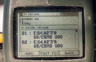
|
Note Almanac Age: 1day
|

|
Taken about 1:45 pm
2025 Jan 10
SV 13 & SV14 with good signal strength
|
Mounting

|
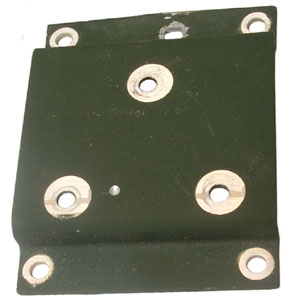
|
Mounting Bracket
The spring loaded pins will stay retracted if rotated.
marked p/n: 907-5006-001
Strange that there's no provision for a padlock.
|
Mounting Bracket Adapter
This adapter bracket has the same four hole pattern as the
plastic PLGR mount. So by using this bracket you
can mount a DAGR in the same holes
that held a PLGR.
The top center hole was made by a prior user.
marked p/n: 987-5177-001
may also be: p/n 987-5007-001
|
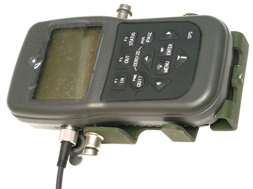
Polaris in military DAGR mount
The threaded hole at the bottom center is for a ground
connection.
|
DAGR Locking Mount p/n: 987-5019-100
|
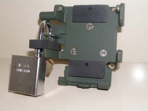
|
DAGR Personnel Case
p/n: 987-5010-001
NSN: 5895-01-521-3111
Front Pocket: Spare battery magazine with batteries.
Rear Pocket; DAGR (or Polaris)
Center Pocket: Quick Reference Guide GTA07-06-003 (pdf:
print at 65%), DAGR-DAGR Cable, Spare Memory
battery.
Flip Down Personnel Case
p/n: 021-0801-040
NSN: 5895-01-586-5644
Antenna
Internal
The internal patch antenna is at the top facing up so the receiver
should be laying flat so the antenna can see the sky.
External
In order to detect the external antenna and not cause an antenna
fault warning message it needs to draw 15 to 60 ma from the
nominal 3.3 Volt supply.
3.3 V / 15 mA = 220 Ohms max to 3.3 V / 60 mA = 55 Ohms min.
Trimble
28367-40

|
Seems to work OK. It
has an SMA connector mag mount.
L1
Volts
|
mA
|
1
|
5
|
2
|
10
|
3
|
14
|
3.188
|
15
|
4
|
17
|
5
|
20
|
|
Trimble
17572-100 16240-00
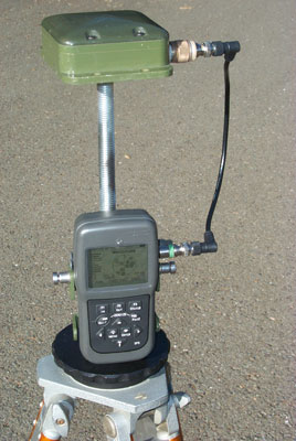
|
This is a survey grade
antenna with 5/8-11 threads.
A couple of tie-wraps holding the DAGR mounting bracket
to the threaded rod.
L1 or L1/L2?
Works well at about 37 mA.
Volts
|
mA
|
1
|
9
|
2
|
20
|
3
|
37
|
3.047
|
37
|
4
|
98
|
5
|
150
|
|
AeroAntenna Technology
AT575-75AW-TNCF-000-RG-36-NM
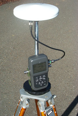 |
This is a survey grade
antenna with North Arrow and 5/8-11 threads.
The threaded rod is rrequired since the TNC connector on
the antenna would otherwise hit the black tripod adpter.
L1
AT575-75
Frequency: 1575 +/- 5MHz(L1)+ Glonass
Polarization: Right Hand Circular
Axial Ratio: 3 db max
Gain: 00,12dB,26dB,36dB
Voltage: 00,05,RG(5-18VDC)
Impedence: 50 OHMs
Connector: TNCF,BNCF,NTPF
VSWR: <=2.0:1
Magnet: NM(No)
Finish: Weatherable Polymer
Color: W,O
Weight:13 oz max.
Volts
|
mA
|
1
|
1
|
2
|
11
|
3
|
17
|
3.167
|
18
|
4
|
23
|
5
|
36
|
|
AeroAntenna
Technology AT2775-42
with the Choke Ring

|
Now being used with Ashtech
Z12R GPS receiver, but probably will work with DAGR.
It should be the best antenna so far for North Finding
because of the choke ring lowering multipath fading.
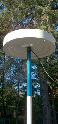
|
Sensor Systems S67-1575-58
 |
This is a passive antenna,
i.e. no gain and is a DC short circuit. The Polaris
Guide protests:
L1
WARNING! EXTERNAL ANTENNA FAULT DETECTED
This is caused by the DC shorted nature of the
antenna. You can see in the photo at left that the
Polaris Guide (DAGR) is working fine with a passive
antenna. All that's needed is a series resistor
choonen to present the minimum acceptable power
consumption to make the receiver happy and allow the
passive antenna to be used. |
Garmin GPSIII Plus Antenna
|
This is a DC open antenna
so the receiver does not know it has an external antenna
attached. Tried to fool the receiver by pointing it
up and covering the top with my hand while not coverning
the external antenna, but this caussed a jamming warning
message. A DC load would needs to be added to try
it. |
KS24019L112C
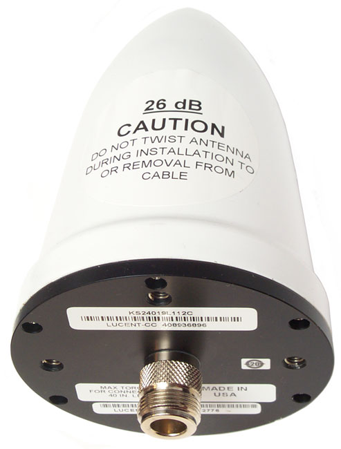
|
Lucent Quad-Helix GPS
Antenna KS24019L112C
5" tall x 3 1/8" dia.
Type-N male connector
4 helicoil inserts in ____" square pattern.
26 dB gain at ______ to _____ DCV.
|
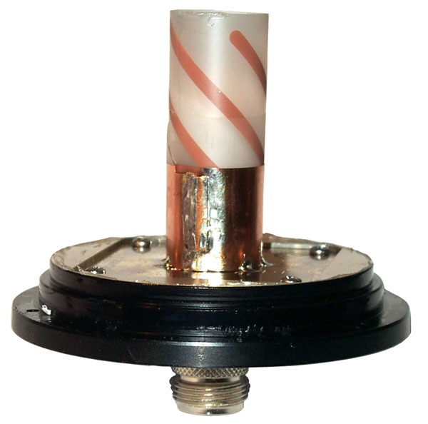
|
The RF amp is below the
ground plane plate.
With a Fluke 87V DMM in diode mode the
antenna Vf (1 ma) reads 1.65 V.
|
RA-1
Magnetic Mount Remote Antenna
Can be used for Gun Laying, i.e. known phase center.
p/n: 13499-013-1981-010, NSN: 5985-01-502-6692
Commercial model: AT2775-1030-SMAF-000-03-26-IM
 |
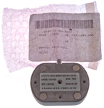 |

|
|
4: magnets (random polarity)
3: 6-32 tapped holes
1: 10-32 tapped hole
0: 1/4-20 tripod holes
|
A 10-32 x 1/4" socket head cap
screw uses a 5/32" hex bit. In a pinch a 4mm
might work. A 4mm ball head works.
|
DC Checks:
Fluke 87V DMM -
|
Red
Center
|
Black
Center
|
Diode
|
0.897 V
|
0.567 V
|
Ohms
|
0.648 M
|
346.7 k
|
DAGR antenna cables for the RA-1
are:
|
When the voltage gets to 2.6 V or higher
the current limits to 35 ma. Only tested up to 5 V
but may work with higher inputs???? Let me know if you know the
upper limit.
Volts
|
mA
|
1
|
3
|
2
|
24
|
3
|
35
|
3.167
|
35
|
4
|
35
|
5
|
35
|
|
DAGR to RA-1 Cable (5m with SMA connector),
p/n: 13499-987-4640-001, NSN: 5995-01-504-1762
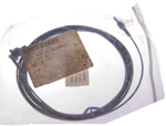
|
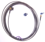 |
DAGR J3 Antenna SMAf
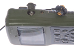
|
DAGR with RA-1 and 5m cable

|
|

p/n: 988-9389-001
NSN 5935-01-534-6963
WANTED:
Name of manufacturer who makes this SMA thumb whee
"Spinner". Let me know.
It may be DCX-CHOL,
have RFQ in the works 22Aug22
|
DAGR to RA-1 Cable (10m with SMA
connector), p/n: 13499-987-5016-001, NSN: 5995-01-521-4244
|
|
DAGR to Helmet Antenna Cable, p/n:
13499-987-7002-001, NSN: 5995-01-521-6753
|
|
SMA DAGR Spinner
p/n: 13499-988-9389-001, NSN: 5935-01-534-6963
Name of manufacturer who makes this SMA thumb whee
"Spinner". Let me know.
|
|
Commercial SMA Wrenches that fit into DAGR
Antenna connector hole. But these are tools that
will be something seperated from the DAGR and can easily
get lost. The plastic thumb wheel is compact and
attached to the DAGR.
KCR Products - Combined
with torque wrench, patent US7080581
-or-
Mini-Circuits: without torque wrench (but about same cost)
HT-2-SMA |
|
Power Splitter
When the Polaris Guide is getting
it's antenna input from a power splitter, like the HP 58535A
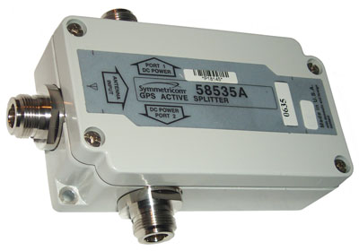
The display shows:
X WARNING
ANTI-JAM ANTENNA
Communication Lost.
Check Cable, Power
and COM Settings
ENTER to Acknowledge
Note: this is different from the open antenna error.
The voltage at the antenna connector (J3) is 3.280 V when there's
nothing connected.
When a 330 Ohm resistor is shunted across the antenna coax the
voltage drops to 3.165 V for a current of 9.6 ma. This turns
off the ANTI-JAM warning.
Breakout Box
Marked: 80063-A3157778
The three terminal pairs are marked:
Ch1 Xmt/Rcv A & B (yellow wire on A, black wire on B)
Ch1 Rcv A & B
Ch2 Xmt/Rcv A & B
This fits either J1 or J2 on the DAGR or the Computer Interface
15-pin connector on a PLGR.
Fig 1

|
Fig 2
 |
Pinout
DB-15
Pin
|
Box
|
Description
|
1
|
|
Ch1 Xmt/Rcv-A
|
2
|
|
Ch1 Xmt/Rcv-B |
3
|
|
Ch1 Rcv-A
|
4
|
|
Ch1 Rcv-B |
5
|
|
|
6
|
|
Ch 2 Xmit/Rcv-A
|
7
|
|
Ch 2 Xmit/Rcv-B |
8
|
|
|
9
|
|
|
10
|
|
|
11
|
|
|
12
|
|
|
13
|
|
|
14
|
|
|
15
|
|
|
The DAGR uses a three terminal power
connector, different from the PLGR's commercial type coaxial two
terminal connector.
 |
The connector is made by TURCK and the
manual says is in their PKG 3M-6 series. But that
connector will not work. The problem is that the
DAGR J4 connector is recessed into a pocket, like the J3
RF connector, and so you can not grab the kunrled part of
the nut as shown in the photo at left. |
 |
Turck will sell a raw connector, but they
are priced about 4X higher than a connector assembled onto
a cable like the one shown at left.
There are at least three versions of the connector
applicable to the DAGR:
- Stock nut as shown at left
- longer stock nut but about the same diameters
- DAGR nut that looks very similar to the spinner used
on the J3 RF connector.
|
SeaLINK USB-RS422
Fig 1 Bag, Cable & CD-ROM
13499 ASSY
426-0228-010
NSN: 5995-01-531-5118
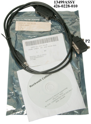
|
Fig 2 Notice (cable) P2 on socket with two
dots.

|
on eBay with the title: "RS-422 to USB CONVERTER CABLE
AN/PSN-13, NSN 5995-01-531-5118"
Under $70 including shipping.
Looks similar to a commercial product the Sealevel Part: 2106
Model: SeaLINK+422, BUT not the same! The
commercial part has a DB-9 connector but the eBay product has a
DB-15 connector that fits the PLGR/DAGR GPS receivers.
Labels
Bag
5995-01-531-5118
Cable Assy
1 ea
C/CA
|
Bag
[bar code]
5995-01-531-5118
CAGE: 13499 PN: 426-0228-010
1 ea
F04701-02-C-0011
F0470102C0111
07/08
|
CD-ROM
Rockwell Collins, Inc.
Software & Manual supporting:
Mfg P/N: 9022
RC P/N: 13499ASY426-0228-010 Rev A
MFR: ONLW9
|
Cable
(pod): 13499ASSY
426-0228-010
(DB-15): P2
(wire): CSA LL80671 AWM IIA/B 80(deg)C 30V FT4 USB
Revision 2.0
USB SHIELDED <28AWG/2C+24AWG/2C>
(UL) Type CM 75(deg)C E129760 SPACE SHUTTLE-D
|
The CD-ROM contains the SeaCOM Version 2.5.13 software for the
USB-RS-422 interface.
Support for Windoes: 95/98/ME/2000/XP
The Setup.inx file contains "Copyright (c) 1990-1999 Stirling
Technologies"
9022.pdf is the SEALEVEL SeaLINK+422 Users Manual
Plugging the USB-A connector into a WIN7 computer results in error
message about drivers.
Serup.exe installs SeaCOM atWIN&: C:\Program Files
(x86)\SeaCOM
DB-15 Connector
Signal
|
Name
|
Pin #
|
Mode
|
GND
|
Ground
|
3, 13
|
|
Rx+
|
Receive Positive
|
4
|
Input
|
Rx-
|
Receive Negative
|
5
|
Input
|
Tx+
|
Transmit Positive
|
9
|
Output
|
Tx-
|
Transmit Negative
|
10
|
Output
|
NC
|
No Connection
|
1, 2, 6, 7, 8, 11, 12, 14,
15
|
|
The modem control signals are biased as follows: RTS is connected
to CTS, DTR is connected to DCD and DSR, and RI is tied inactive.
SeaCOM
for Windows Version 3.7.5. (there is also a Linux
Ver 1.3.2) 32-bit or 64-bit Microsoft Windows 7, 8.1,
or 10
By looking at my USB devices after plugging in the cable I can see
it's at COM10 so that was selected in the SeaCOM Port Manager
software and "APPLY".

|
But do not know how to use the WinSSD
program.
In addition to this program there are other WIN software
packages
that need to be loaded.
|
|
|
Scratches on LCD Plastic
Tried Meguiar's 17 Clear
Plastic Cleaner - but it's only for "fine
scratches". it polished the plastic but did not
remove the scratches.
|
|
|
This is what the screen
looked like after the Meguiar's.
|
|
Next will use Novus #3
Heavy Scratch Remover by hand first, then if necessary
using a buffing wheel on a drill press.
|
|
|
Rockwell Patents
Also See GPS
Patents.
In addition to the patents listed
here Rockwell has many many more. They are heavily into all
parts of GPS including satellites and aircraft systems in addition
to the ground units that are the focus of this web page. In
addition they have patents that make use of GPS for things like
factory automation.
7142159 Pseudolite navigation system, Nov 28, 2006, 342/386
; 342/357.02; 342/357.06; 455/13.2 -
Uses communication satellites with
custom up and down link signal formats to get around jamming or
poor visibility
7230999 Method for extended coherent data demodulation for GPS
receivers, Jun 12, 2007, 375/316; 375/340; 701/213; 701/214;
701/215; 329/304 -
Uses two I&Q signals offset in
time and then differenced.
7190746 Multiple lobe dot product detector for
M-code GPS receivers,
6973150 Cycle slip detection using low
pass filtering, Dec 6, 2005, 375/371; 375/376 -
Works with single antenna systems.
6959057 Method of
enhancing signal tracking in global positioning system receivers
Instead of using a FFT method of
searching for the signal frequency, a filter bank is used which is
faster and more robust
6738015 Vector extended range correlation
tracking of global positioning system (GPS ...
A Kalman filter uses pseudorange
errors to calculate position and velocity corrections in order to
better process weak signal code tracking
6687316 High resolution correlator technique for
spread spectrum ranging system code ...
Multipath mitigation by using three
high resolution correlators, one early, one on time, and one late
allowing interpolation
6683867 Parallel precise
time transfer to multiple GPS units
Often GPS receivers are turned off
prior to a mission to conserve battery power. Then just
prior to commencing the mission are powered up and loaded with
precision time and position data from a receiver that's been kept
hot. When there are many receivers that are off this patent
teaches combining the 1 PPS with the serial data onto a single
data line.
6647080 Carrier phase
initialization with sub-LSB accuracy
A method of computing the command
word to an NCO to get sub-LSB accuracy
6636558 Multipath mitigation approach for spread
spectrum ranging/positioning systems
Multipath is detected as slope
differences prior to and after the correlator peak
6590528 Low cost interference reduction system
for GPS receivers
Multiple antenna system in front of
GPS receiver
6570531 Satellite navigation receiver designed for
compatibility with aircraft automatic landing systems
An attempt to recognize failures by
comparing two GPS solutions
6556167 Direct acquisition of very large PN
sequences in GPS systems
Direct acquisition of the P(Y)
sequence without the Hand Over Word from the L1 C/A code by
breaking up the P(Y) code into a number of sub sequences and
testing all of them. Instead 15000 sub sequences that have
gaps between them are repeatedly tested thus covering the
gaps. 320 seconds should be enough time to search the full
weekk of code. This is an important capability for cases
where the L1 C/A code is not available, like when it's being
jammed.
6501424 Use of GPS
correction data on trans-oceanic route
HF radio is used to send the
airplane differential corrections like are now sent to coastal
ships using LF radio
6421006 GPS augmentation using time offset code
modulation
By offsetting the PN code by a large
amount (hours) relative to the actual GPS time pseudolites will
not interfer with normal GPS operation
6393291 Method and apparatus for deriving a high
rate output in a GPS system
Combines kinematic and differential
corrections to achieve high rate precision corrections
6388611 Method and system for dynamic
surveillance of a remote object using GPS
Combines GPS and TV image to
determine target coordinates
6369752 Direct acquistion of very large PN
sequences in GPS systems
see 6556167 above
6359585 Apparatus and method of determining an
orientation of a GPS receiver
Based on using a directional antenna
in the GPS receiver either in max signal or null methods.
6336076 Long range GNSS ephemeris data transfer method and apparatus
using the same
Pseudolites are sued to transfer
ephemeris data - maybe when the L1 C/A code is not
available/jammed
6336061 System and
method for attitude determination in global positioning systems
(GPS)
Uses two receiver - antenna units
6311127 Satellite navigation system having
redundant signal processing and matched ...
Aimed at aircraft systems that need
to know if they are not working
6307514 Method and system for guiding an
artillery shell
Uses a four segment antenna that can
be electronically steered
6297769 System and method to estimate carrier signal in global
positioning systems (GPS)
A dual receiver approach to attitude
determination
6272174 Multiple frequency bin processing
see 6959057 above
6266009 Method to improve carrier
smoothing of code pseudorange for global positioning and GNSS
receiver implementing the same
By using dual frequency carrier
phase methods the ionospheric variability is reduced
6259400 Fast acquisition of GPS signal corrupted
by doppler or time delay effects
Artillery shell converts GPS to
another frequency which is reconverted back to GPS at a base
station.
6256583 GPS attitude determination system and
method using optimal search space ...
Optimized integer ambiguity
searching
6208289 System and method for monitoring and
reporting GPS pseudo range correction data
A second fixed GPS receiver is used
to test differential correction data before it's sent to mobile
units
6204806 Method of enhancing receiver autonomous
GPS navigation integrity monitoring ...
For aircraft fault finding
6198430 Enhanced differential GNSS
carrier-smoothed code processing using dual ...
Dual GPS frequency differential
corrections
6188353 Interbuilding and urban canyon extension solution for global
positioning systems
Concept for a second positioning
system powered by utility lighting
6166683 System and method for high-integrity
detection and correction of cycle slip ...Dec 26, 2000, 342/357.04
; 342/357.11
Excludes satellites where a cycle
slip would be hard to detect and uses the delta phase from two
antennas to detect a slip
6163021 Navigation system for spinning
projectiles
Magnetic sensor used to generate a
despun reference frame for an INS system and GPS receiver
6098547 Artillery fuse circumferential slot
antenna for positioning and telemetry
see 6307514 above
6069585 Personal direction finding apparatus,May
30, 2000, France
342/443 ; 340/979; 342/147;
342/195; 342/29; 342/417; 342/450; 342/454; 342/455; 367/107;
367/116; 367/124; 367/125; 367/126; 367/99; 381/300; 381/309
Stereo headphones provide an audiable signal to maintain a given
magnetic bearing
6067503 Method and apparatus for compensating unexpected frequency
shifts in positioning receivers
Method to overcome the launch high G
shock that can break lock of GPS receiver in artillery shell
6064942 Enhanced precision forward observation
system and method
6020854 Artillery fuse
antenna for positioning and telemetry
Design compatible with the above GPS
and telemetry antennas
6018314 Method for obtaining PPS accuracy using
an unclassified GPS receiver ...
About limiting the security boundry
inside a GPS receiver to lower it's cost
6016121 Multiple frequency GPS receive operation
using single frequency sequencing
5990831 FFT implementation of digital antenna
arry processing in GNSS receivers
5 more?
5990826 Interbuilding and urban canyon
extension solution for global positioning systems
5943008 Single global positioning system receiver
capable of attitude determination
5940027 High accuracy low power GPS time source
Time of day clock for GPS receiver
(why better than the DS32khz?)
5903654 Method and
apparatus for eliminating ionospheric delay error in global ...
5886665 GNSS local constellation/acquisition
aiding system
5883597 Frequency translation method and circuit
for use in GPS antenna electronics
5883596 ?
5883595 Method and apparatus for mitigating
multipath effects and smoothing ...
5748136 Electronic landmark
enhancement to GPS based navigation systems
5742207 Tracking loop
having instantaneous frequency shift protection
5606732 Direct connect
radio and antenna assembly
5552794 Position estimation using
satellite range rate measurements
5495408 Method and apparatus for signal tracking
using feedback control loop
5488378 Method and apparatus for determining positions on the earth
corresponding to an observed rate of change of satellite range
Cold start position improvement by
using the first pseudorange and doppler shift
5403197 Antenna extender apparatus
Looks like the
PLGR
antenna
Not GPS, but based on IR between
vehicles on digital highway
5202693 GPS signal processing with 5-level
carrier injection demodulation function ...
5021792 System for determining direction or
attitude using GPS satellite signals
"A system for determining spatial
orientation based on the carrier phase of signals received from a
set of GPS satellites. The system comprises an antenna array
including a number of antennas coupled to GPS radio receivers, a
mechanism for reconfiguring the positions of the antennas within
the array and a signal processing module for processing the data
collected by the antennas and the receivers. The mechanism for
reconfiguring the antenna array is adapted for exchanging the
positions of one pair of antennas and for rearranging the antennas
from collinear into non-collinear patterns. Phase measurements are
taken by the antennas and their associated receivers, both before
and after antenna exchange and after antenna rearrangement in
order to provide the data necessary to determine direction or
attitude."
This may be the method used in the dual receiver GLS.
4910525 Audio verification system and technique for GPS receivers,
Mar 20, 1990, 342/418 ; 342/356 -
Rockwell has a patent on making the
Doppler shift from a selected SV into an audio signal.
but based on the issue date doubt
this is currently being offered.
Pruchasing Polaris
Starting Sep 13, 2008 I am trying to
pruchase one or more Polaris receivers. Which ones and what
accessories depend on the quote. On 14 Oct 2008 I learned
that a number of the items that I have asked for quotation are non
standard and must be priced which can take up to a month.
My current thought is to get the Polaris Guide and accessories for
a single receiver North Finding system, except instead of getting
it's case get the case for the dual receiver North Finding System
to that it would be easy to expand to that system. The
operational difference between the single and dual receiver
systems is not yet known, but has been requested.
The long process was expected since when purchasing a battery
adapter for the PLGR a similar thing happened. It took a
very long time to buy a simple part. I think this is because
they are setup to sell to the U.S. Government and need a lot of
paper work to do that so do poorly when trying to sell a simple
item.
Glossary, GPS
MPE Minature PLGR Engine
WAAS (
Wiki)
Wide Area Augmentation System promoted by the FAA, geostationary
satellites transmit GPS corrections similar to RTCM-104
differential corrections
WAGE (
Wiki)
Wide Area GPS Enhancement, military version of WAAS (< 4
meters)
GB-GRAM Ground Based - Gps Receiver Application Module uses the
same SAASM
ICD-numbers
ICD-GPS-060 Have Quick
ICD-GPS-153 Programming serial Interface includes both hardware
and commands
ICD-GPS-200 Signal from satellites
SINCGARS - Single Channel Ground and
Airborne Radio System, frequency hopping mode needs Time Of Day
and date
Have Quick (
Wiki)
(SS110990) - Frequency hopping mode needs Time Of Day and date
NMEA 0183 (
Wiki)
National Marine Electronics Association spec for serial data
messages to allow interoperation of instruments 4800 baud, limited
capability
RTCM-104 (
Wiki)
TTFF
DS101 (Wiki:
Fill
Device)
DS102 (Wiki:
Fill
Device)
PPS (
SPS (<100 meters)
PLGR Precise Time (SS-M/V-500)
SA
AS
SAASM
Codes
Frequency
Channels
TOD Time Of Day
GPS Global Positioning System (
Wiki
has a good treatment)
References
[1] J. Kelly, “SPS
v. PPS: Why Military GPS Applications Require Military GPS”,
presented at ION GPS/GNSS 2004, 21-24 September, Long Beach, CA.
Proceedings pp. 533-543.
[2] MIL-STD-2525B
“DoD Interface Standard, Common Warfighting Symbology”,
January 30, 1999.
[3] FM
101-5-1, “Operational Terms and Graphics”, United States
Marine Corps, September 30, 1997.
[4] MIL-DTL-89045, “Detail
Specification, Geospatial Symbols for Digital Displays
(GeoSym®)”, National Geospatial-Intelligence Agency’s National
Center for Geospatial Intelligence Standards (NCGIS), June 17, 2004.
[5] TC
5-230, “Army Geospatial Guide for Commanders and Planners”,
Headquarters, Department of the Army, August 20, 2003.
[6] “Commercial Terrain
Visualization Software Product Information”,
http://www.tec.army.mil/td/tvd/survey/ survey_toc.html, US Army
Corps of Engineers, April 21, 2005. https://www.agc.army.mil/
[7] MIL-STD-2411, “Military Standard, Raster Product Format”,
Defense Mapping Agency, August 16, 2001. - Sustainability
[8] MIL-STD-2407, “Interface Standard for Vector Product Format
(VPF), Defense Mapping Agency, October 26, 1999. - Sustainability
[9] “Map Projections
– A Working Manual”, United States Geological Survey
Professional Paper 1395, First Edition, 1987.
[10] “An Album of Map
Projections”, United States Geological Survey Professional
Paper 1453, First Edition, 1989.
[11] MIL-C-89038, “Military Specification, Compressed ARC Digitized
Raster Graphics (CADRG)”, Defense Mapping Agency, October 6, 1994 -
Sustainability
[12] “ArcGIS - The Comprehensive Geographic Information System”,
Environmental Systems Research Institute, Inc. (ESRI™), GIS and
Mapping Software, http://www.esri.com/software/arcgis/,
April 8, 2005. $100/year
for personal use - Rockwell
Collins - DAGR
- Polaris
Guide - GB-GRAM
- Polaris
Link -
Ref 13.
Assured PositioningNavigation
and Timing (APNT) - works even when GPS is jammed
Ref
14. Why these aircraft are MORE important than fighters,
40:25 - @10:30:
9-Line-Briefing
Ref
15. Millennium
7 * HistoryTech - 2024Jun30: Ukraine:
Why JDAMs and SDBs are Missing Targets, 30:56 - GPS Jamming
& Spoofing
@03:38
01 What Happened? Excaliber Artillery Round (Wiki),
HIMARS (Wiki), JDAM
(Wiki),
GLSGB (Wiki)
- only worked for a few months then fell out of use
@08:28
02 What is GNSS? (Wiki)
many systems, used for timing in critical applications like
electric grid and cell phones.
@12:59
03 Jamming & Spoofing - spoofing done by playback of encrypted
signal,
@17:46
04 Counter-Measures a drone can act as a high power GPS
satellite (harder to jam) but it requires a specalized GPS
receiver that works with something other than TLEs (Wiki)
@25:47
05 Alternatives - altPNT, Datalinks, like Link 16 (Wiki) (BC: also
easily jammed), Signals of opportunity (also easy to jam or fake),
improved INS (Wiki)
(gyro drift is a problem), Terrain Mapping (Wiki)(no clock
signal), Celestial Navigation (Wiki),
Crustalmagnetics (Wiki)
My comment:
Links
U.S. Army Product Manager, GPS
-
Space and Naval
Warfare Systems Command (SPAWAR) - GPS & Nav
Systems -
Wiki: GPS
- GPS
Modernization - GPS Signals
- Wide
Area
Augmentation System (WAAS)
-
Talon
NAMATH, Link 16(Wiki),
ZOAD, SBIR, and Other (GPS) Code Words - GBU-39 (Wiki)
Orbit
Determination
and
Satellite
Navigation
- Sensor
Systems
for
Satellite
Tracking
- Precision
Modeling
for
Orbit
Determination -
- The
Kalman
Filter:
Applying
the Scientific Method
- Tracking
Geosynchronous
Satellites
with
GPS
SPACEBORNE
GPS INFORMATION SITE
- SGPS
REAL-TIME ORBIT DETERMINATION
Air Force Space Command - High
Frontier Vol 3 Nbr 2 "Global
Positioning System International Challenges and Opportunities in
the 21st Century"
Caltrans -Survey
Manual - Ch 4 Survey
Datums -easy to understand explanation about how NAD83
differes from NAD27 - Ch
9 Control Surveys -
GPS
Explorer - a page to locate GPS reference stations and
geodetic markeres
HawkEye 360
- HawkEye
360 Signal Detection Reveals GPS Interference in Ukraine
-
NavSpark NS-HP-GN5 : PX1125R
L1/L5 RTK BREAKOUT BOARD - GPS L1 / L5;
Galileo E1 / E5a; Beidou B1I / B2a; QZSS L1 /
L5; GLONASS L1; NavIC L5; 1cm + 1ppm RTK accuracy in
seconds - used with Ardunio, 2 required for RTK.; $50 for board,
$40 for chip. -
SURVEY
ANTENNA BASE & ROVER PAIR RTK KIT - $600 - Getting
Started Guide.pdf
Back to Brooke's PRC68, Products for Sale,
Navigation, Military
Information, Personel Home page
page created 3 Oct 2008.
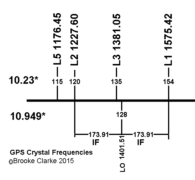
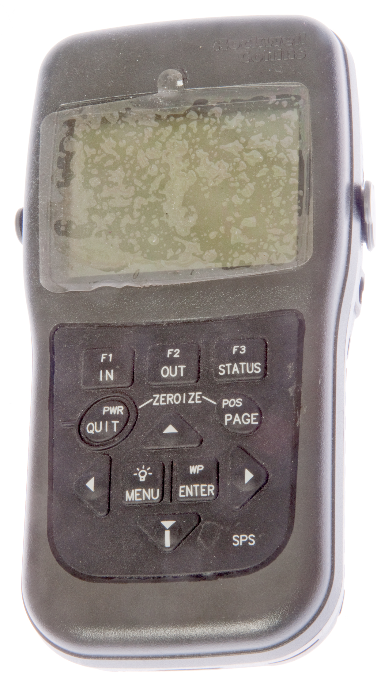
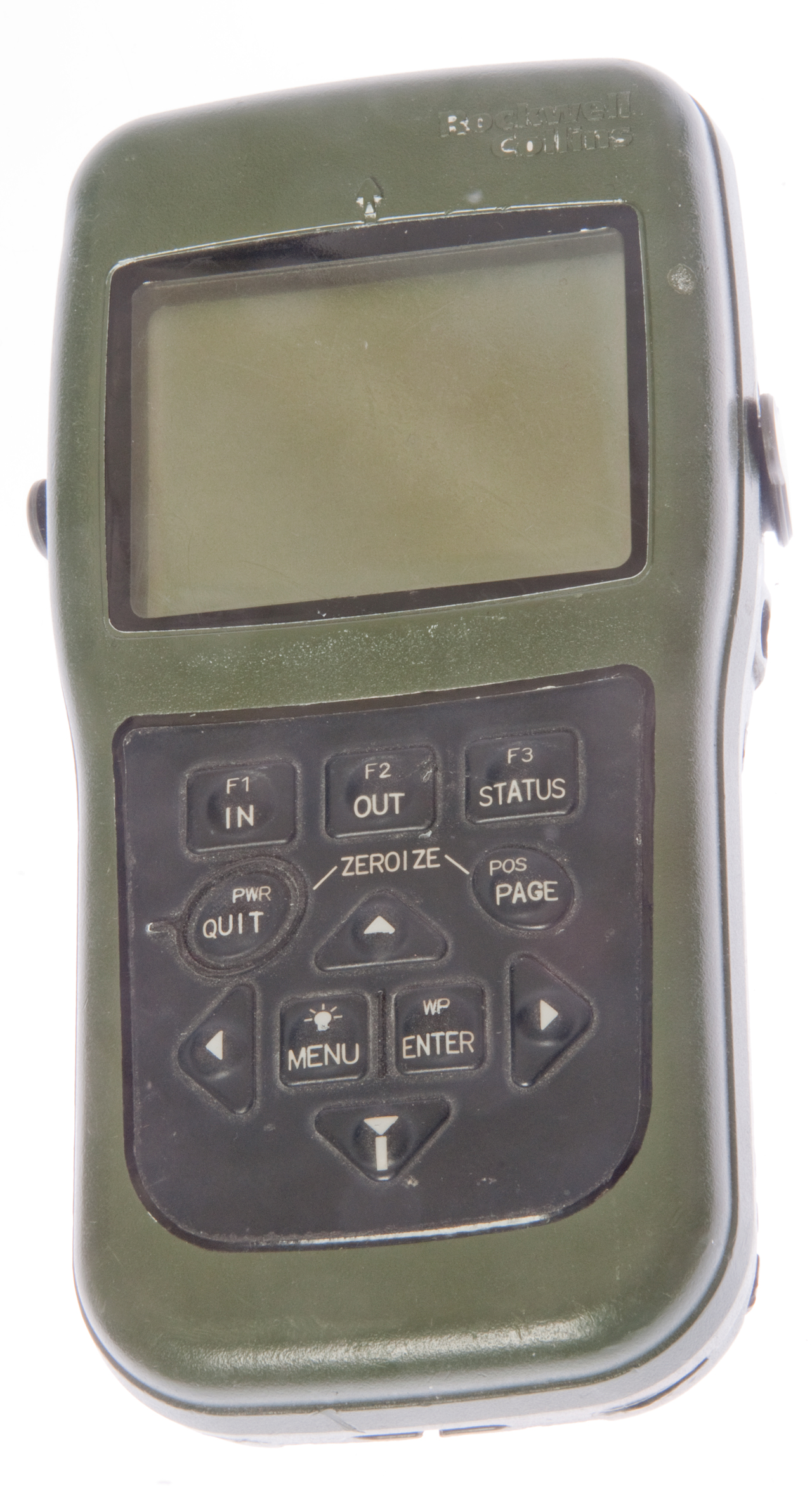
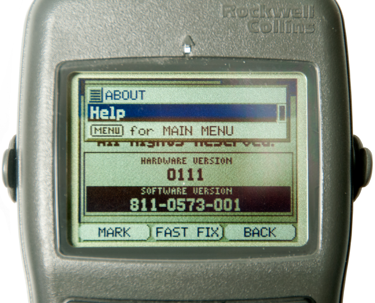

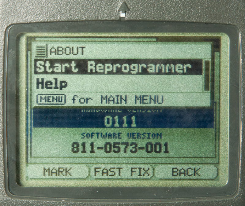
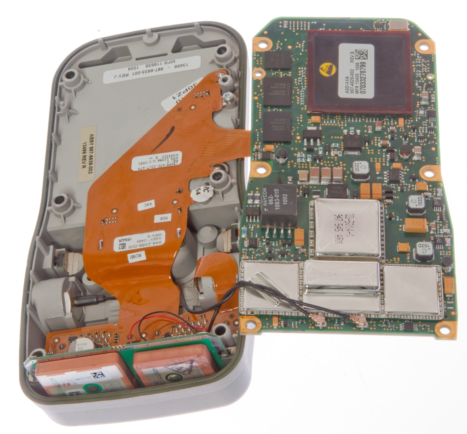
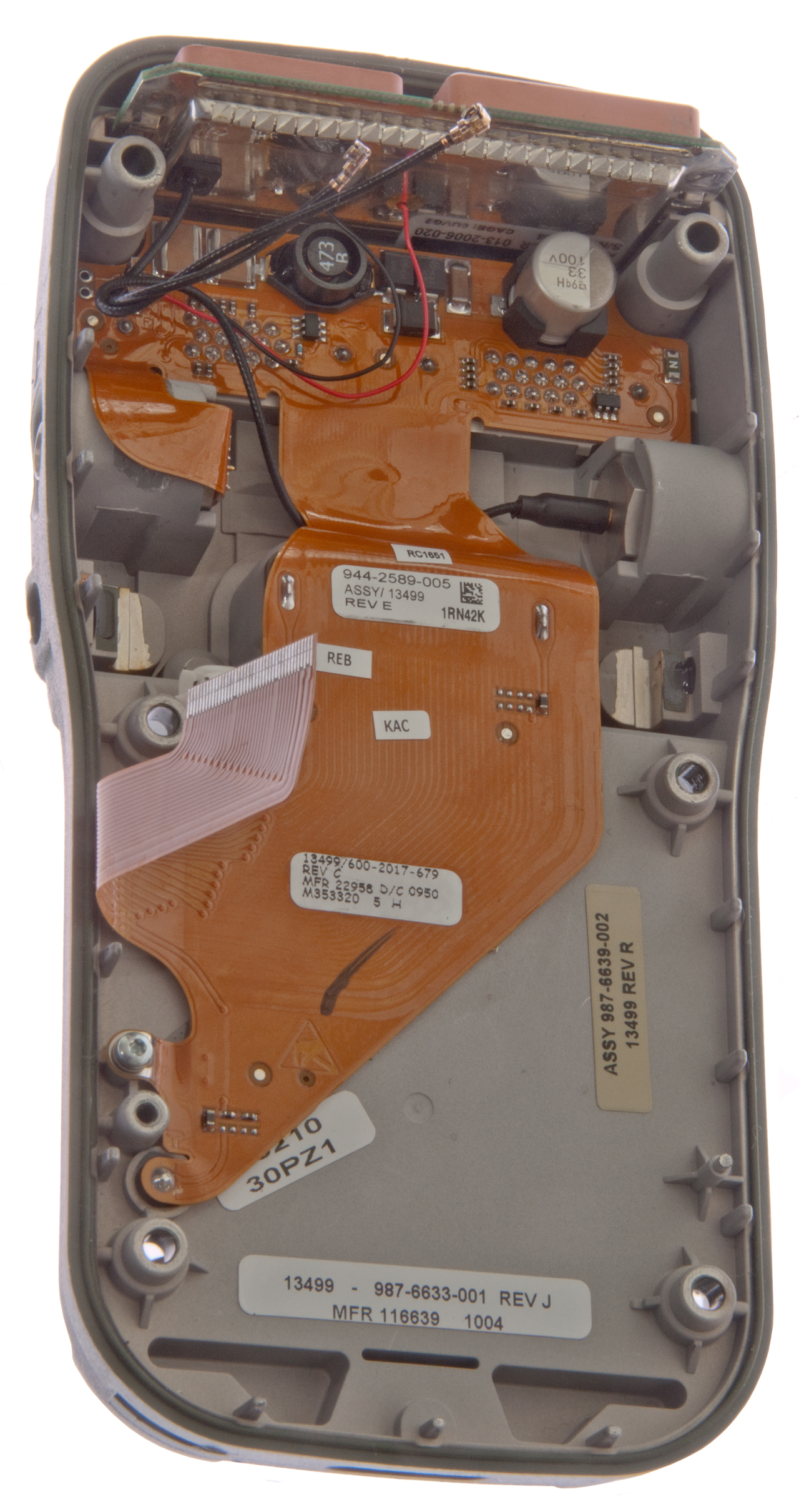

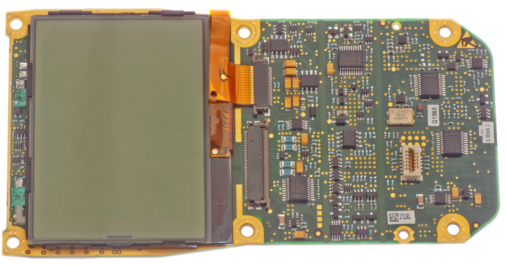


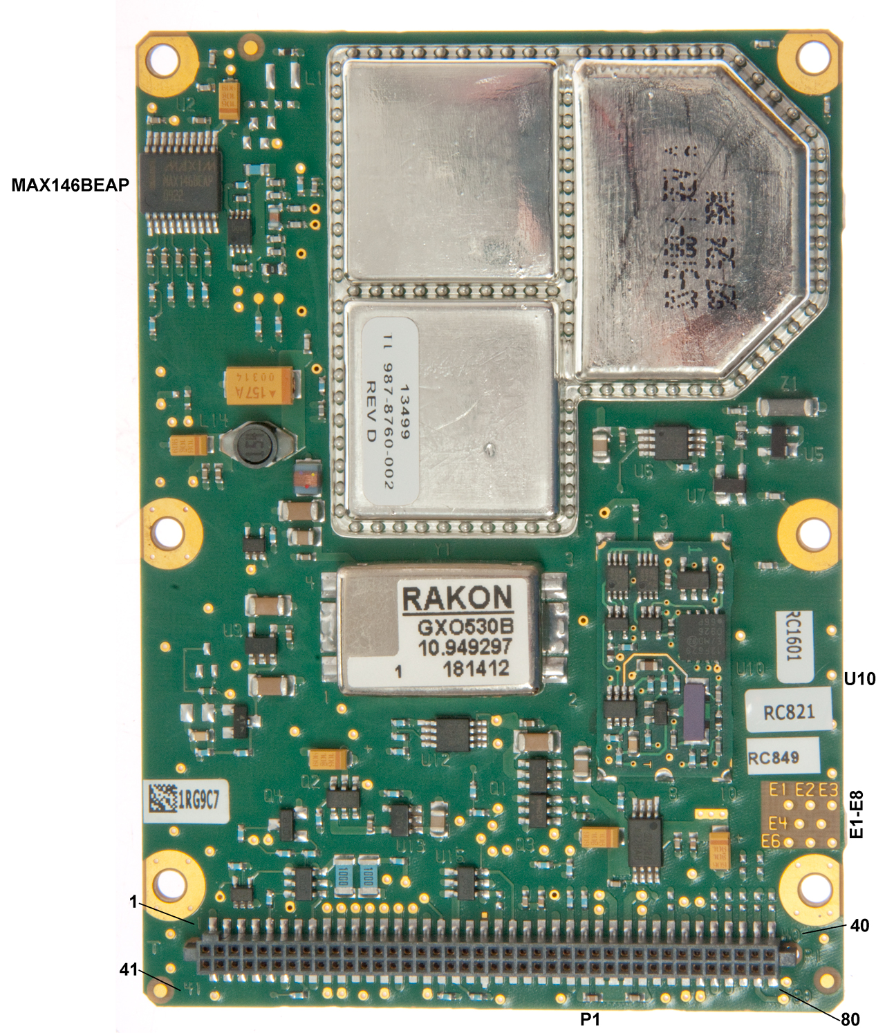

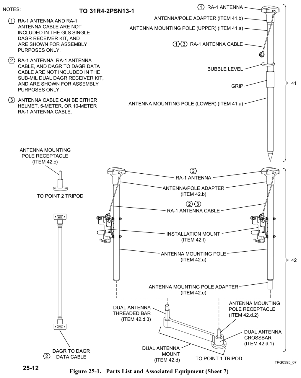
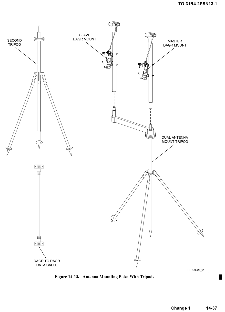


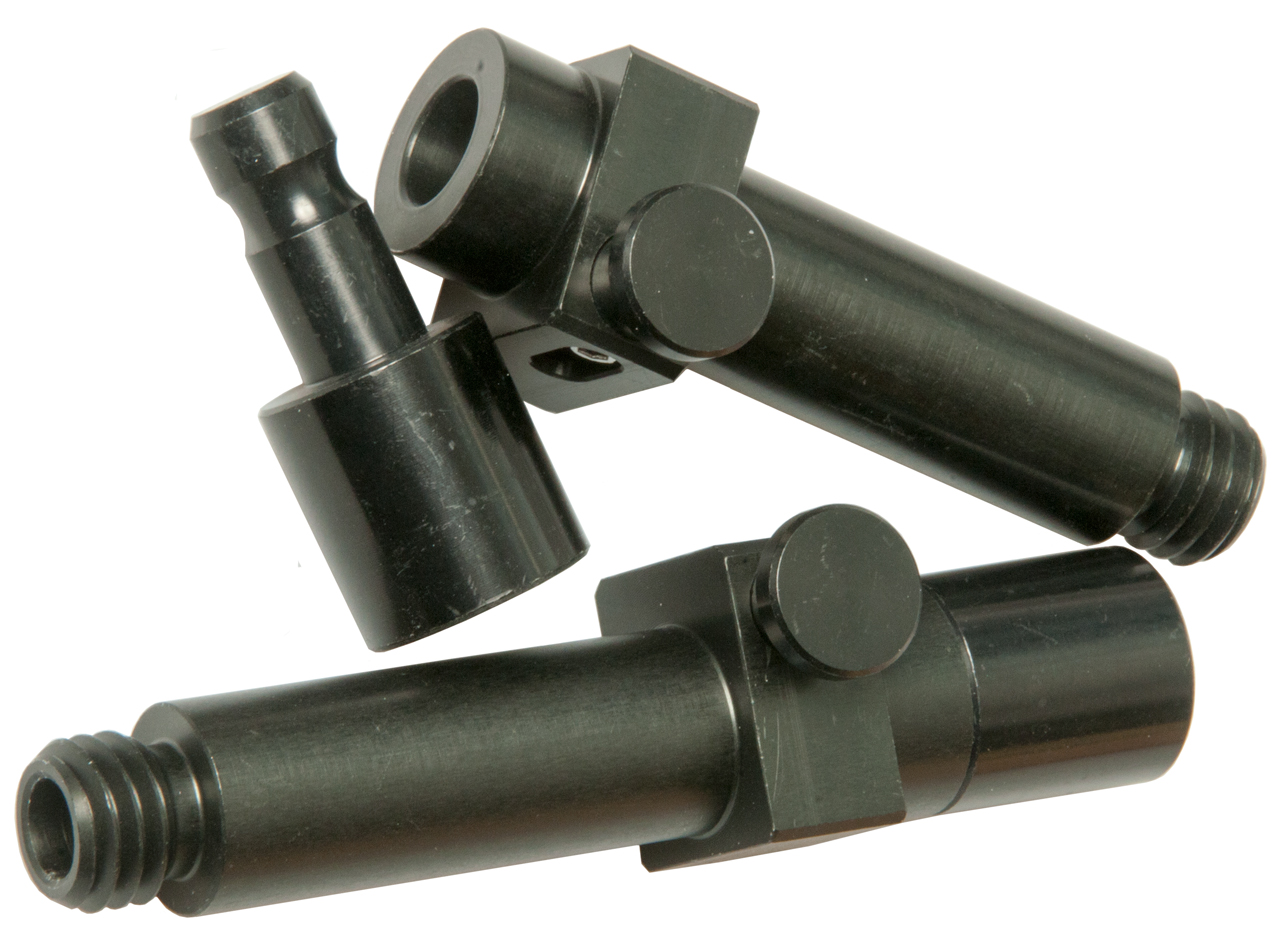
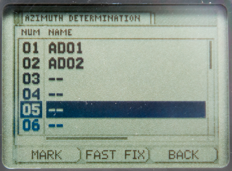
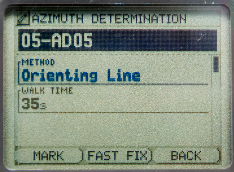
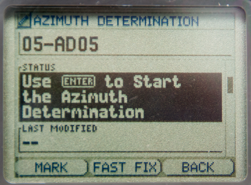


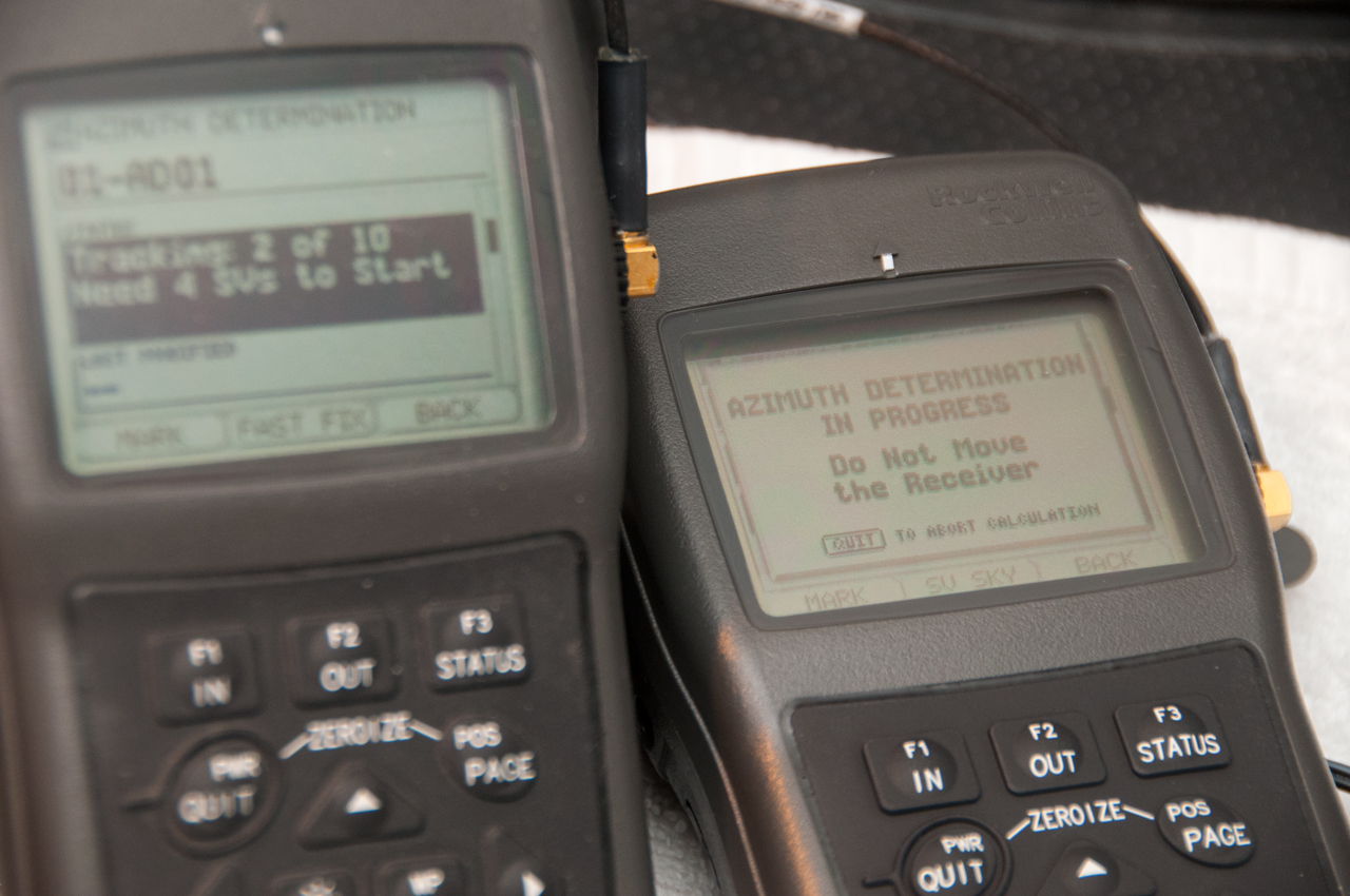


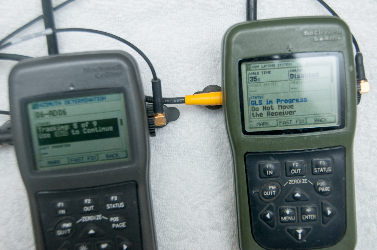
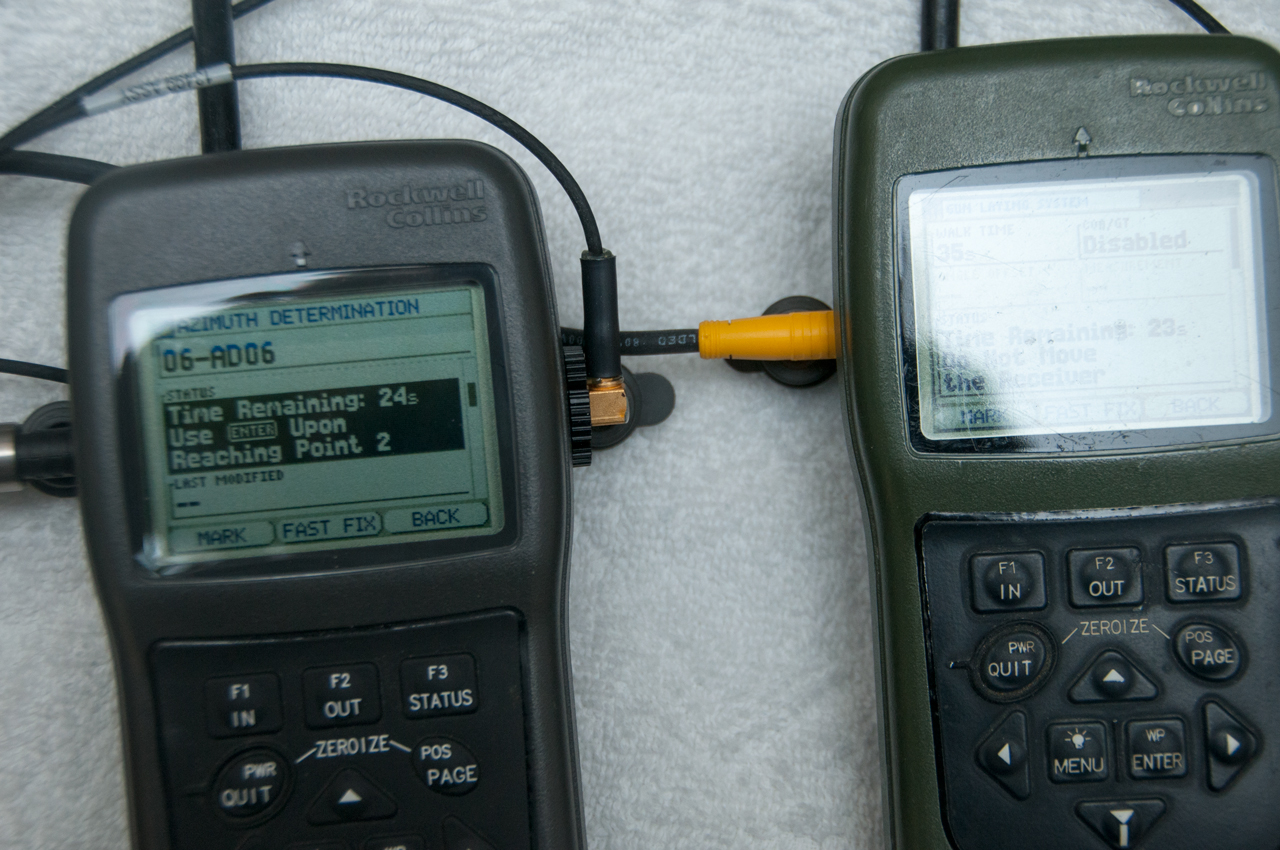


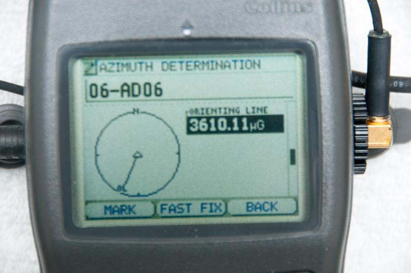


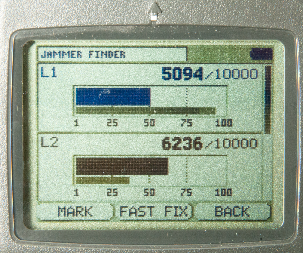


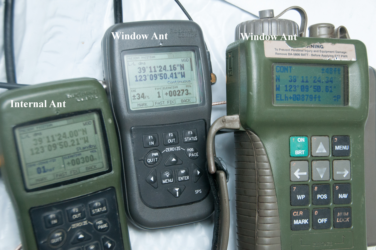


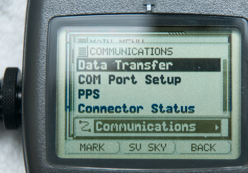
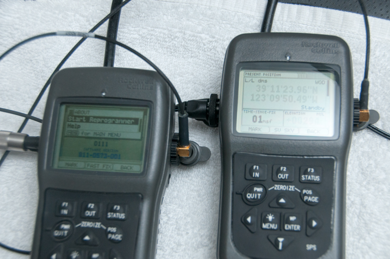
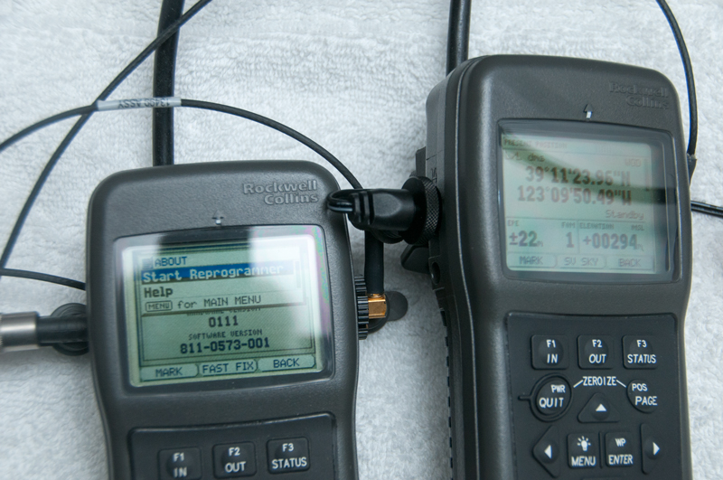
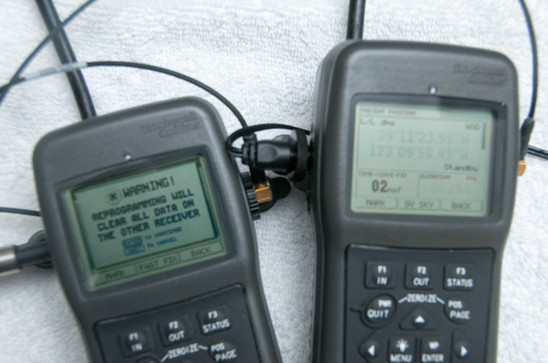


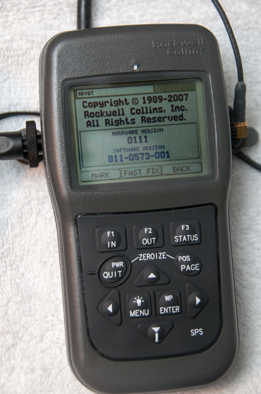
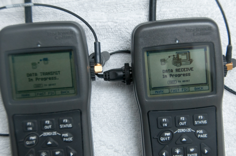


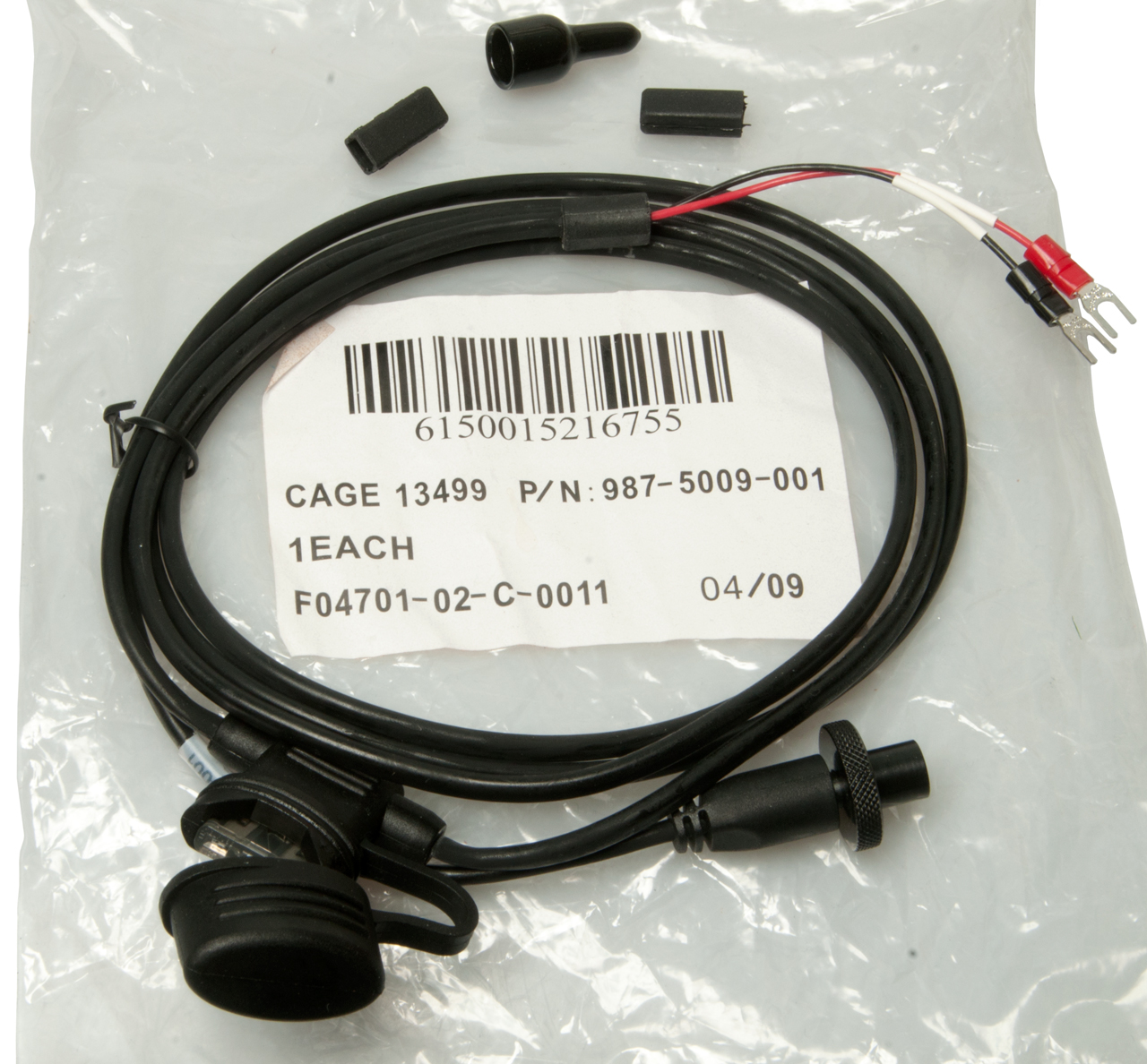

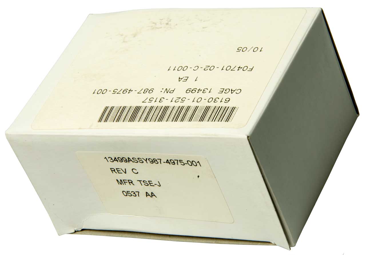


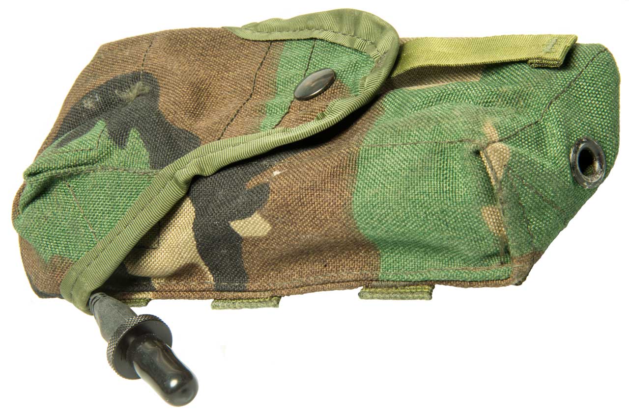
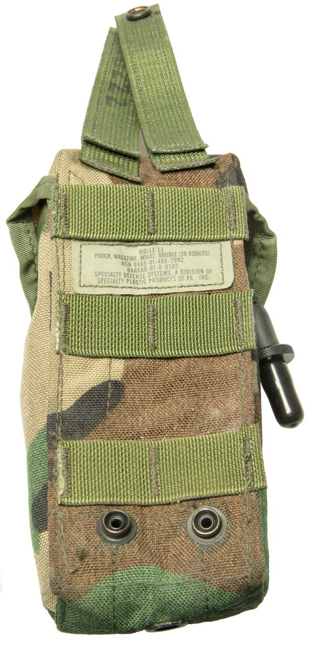
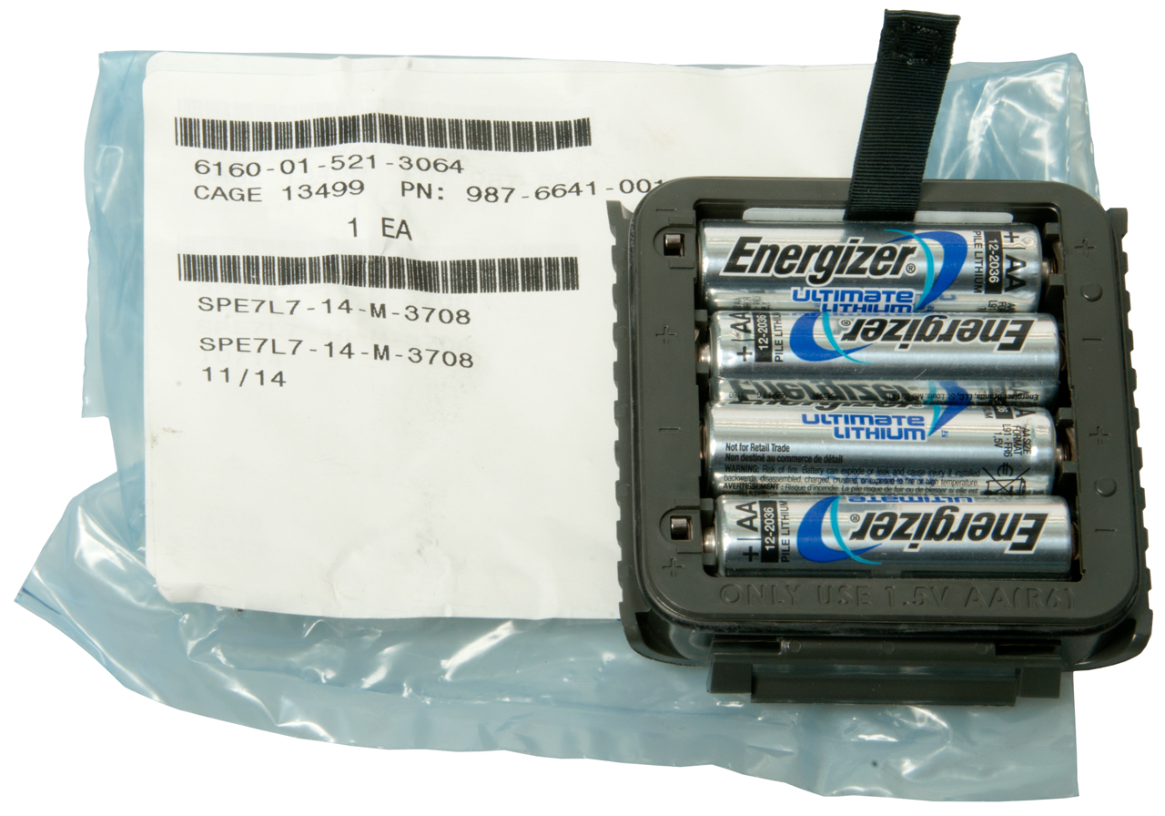
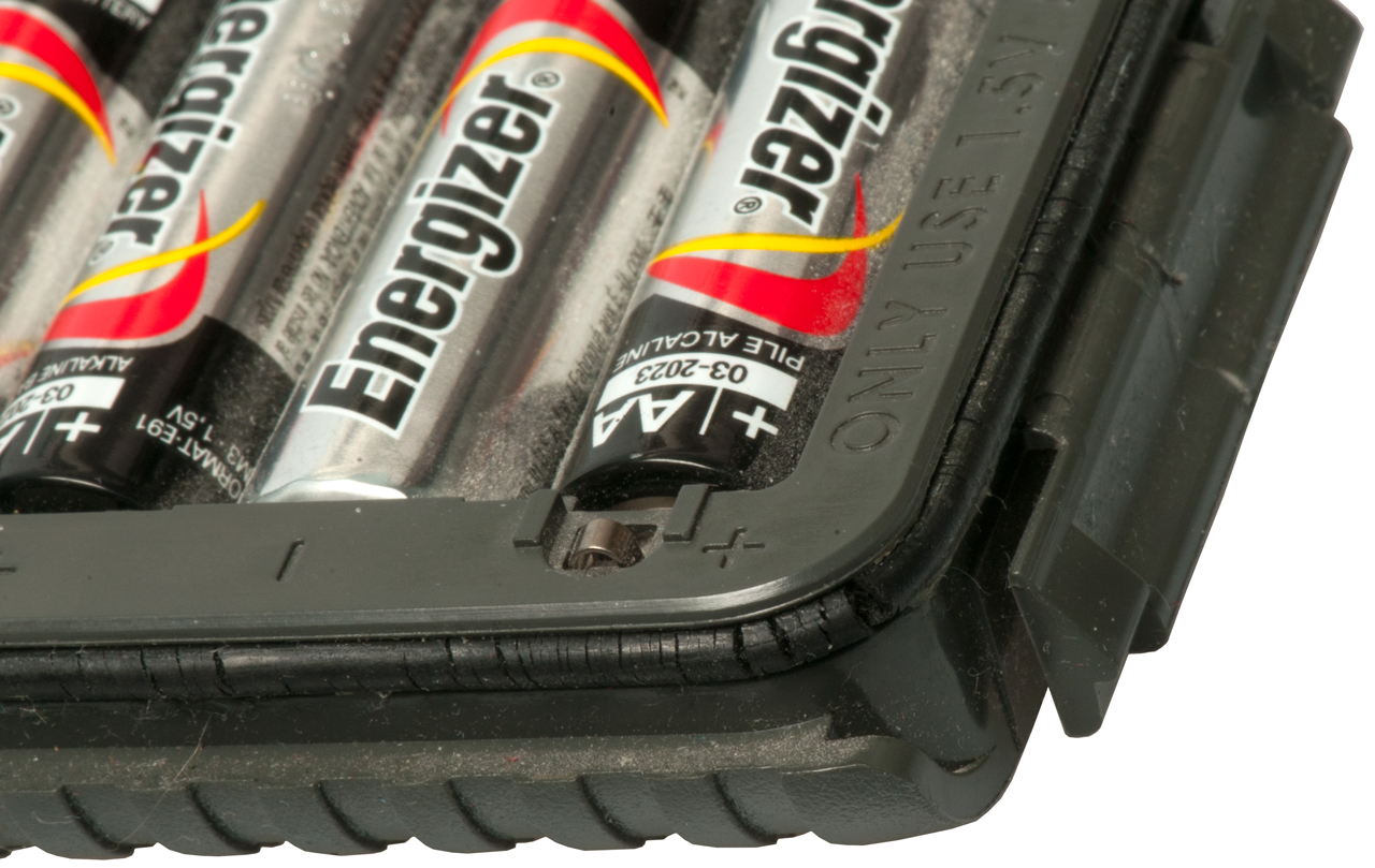
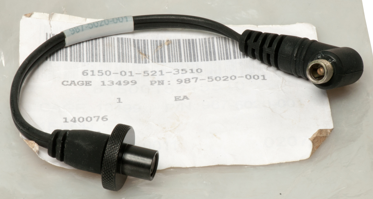

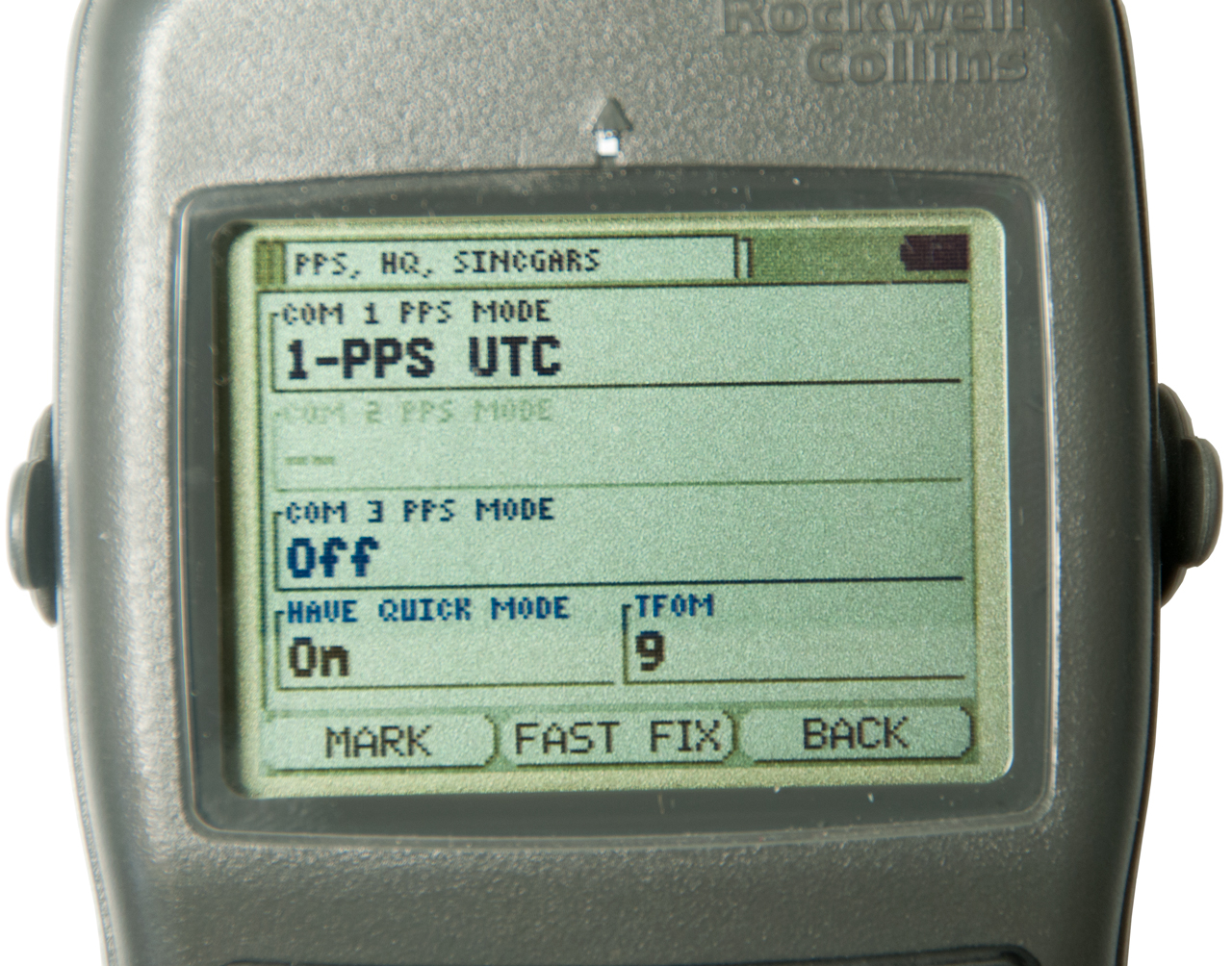
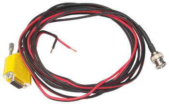

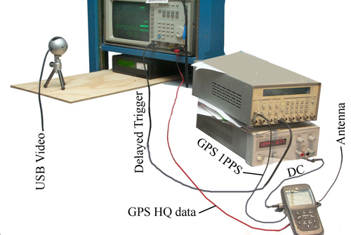
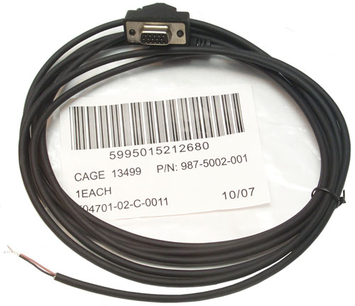


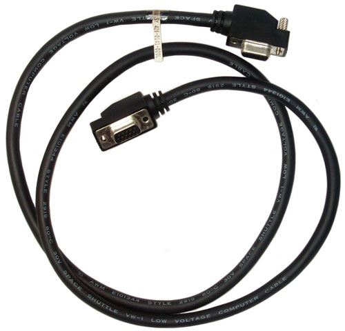
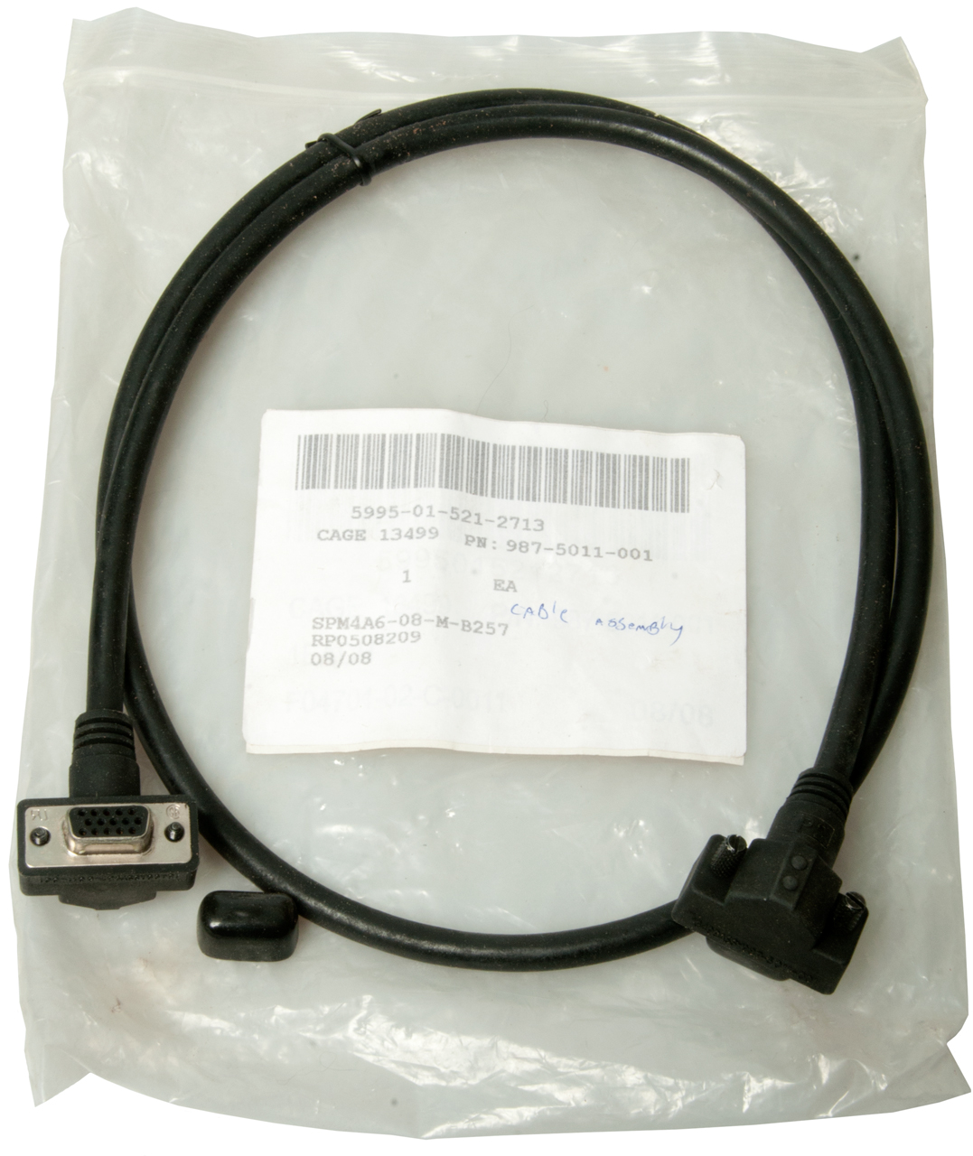


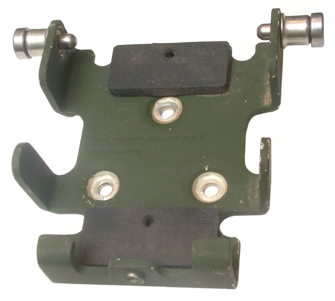
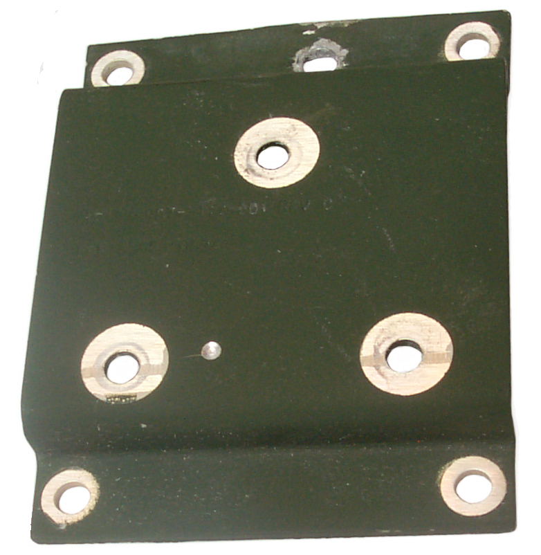
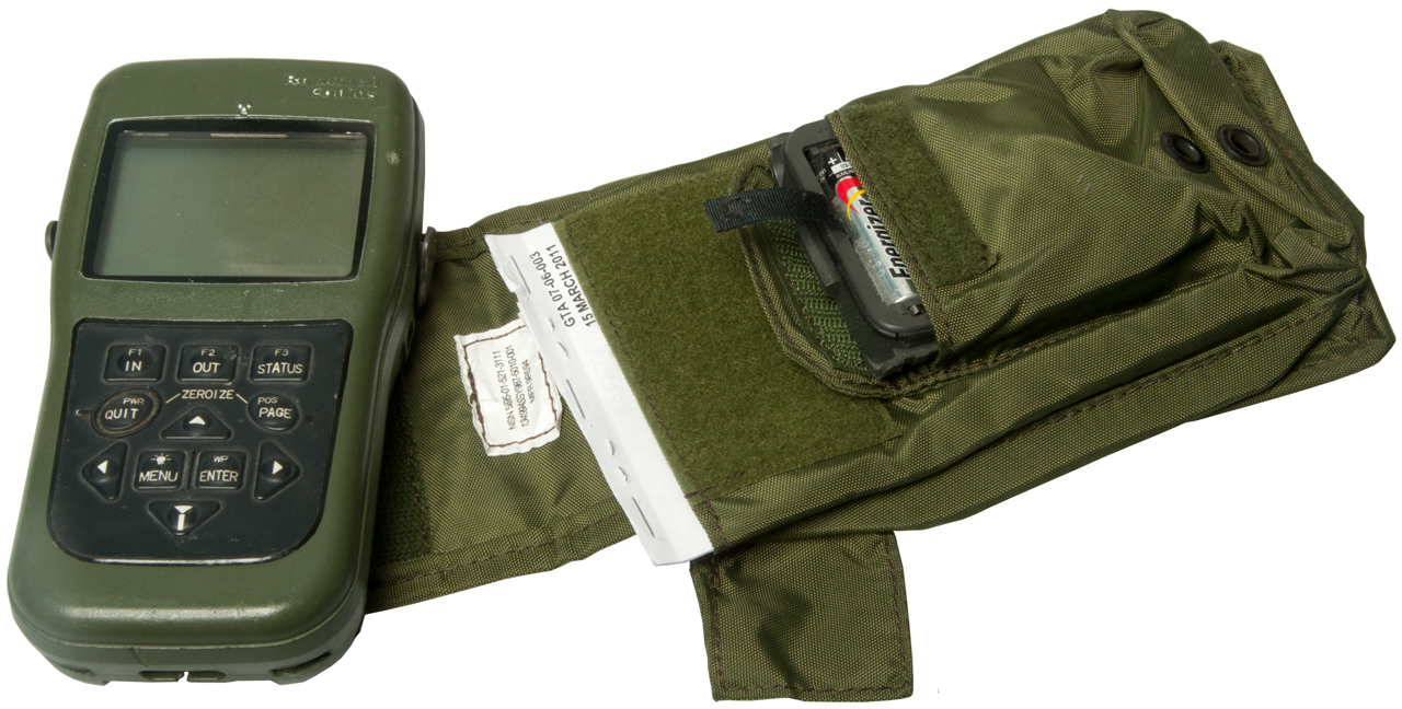
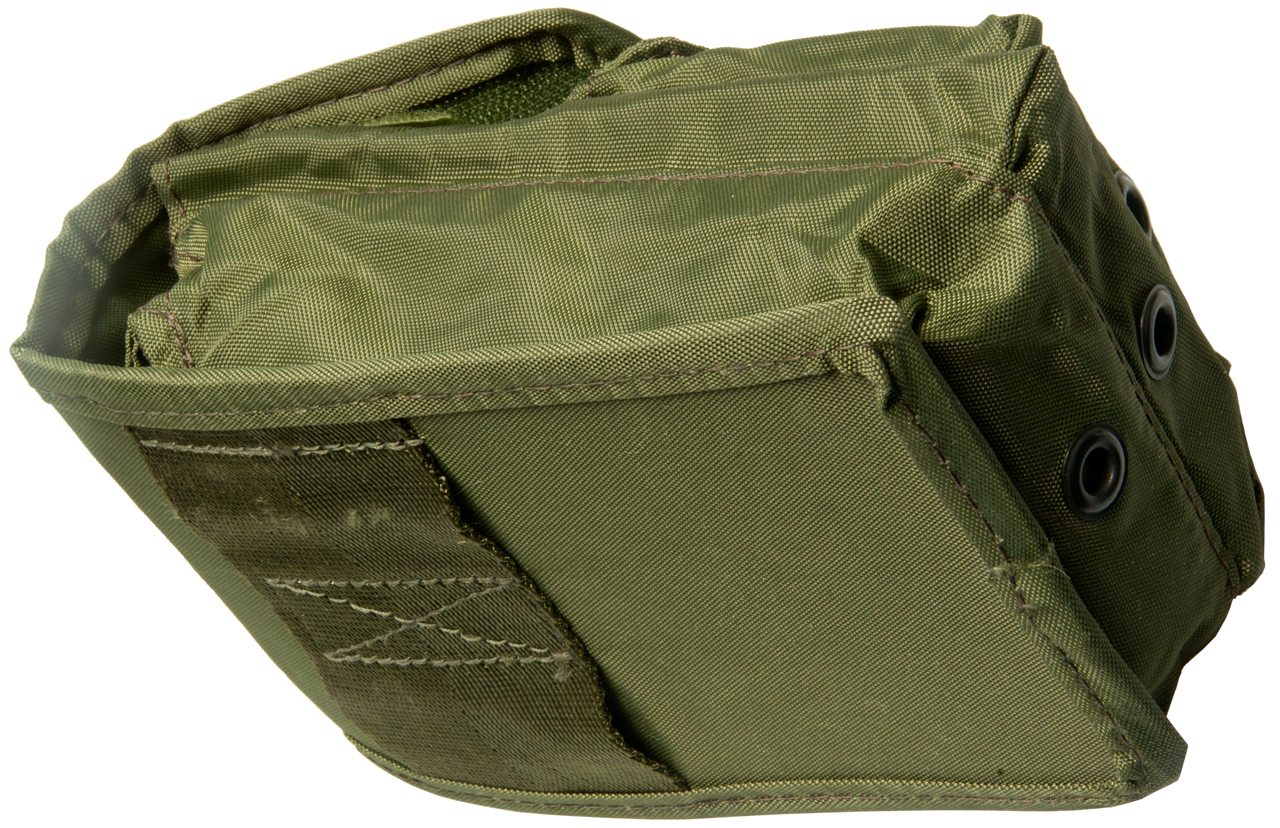
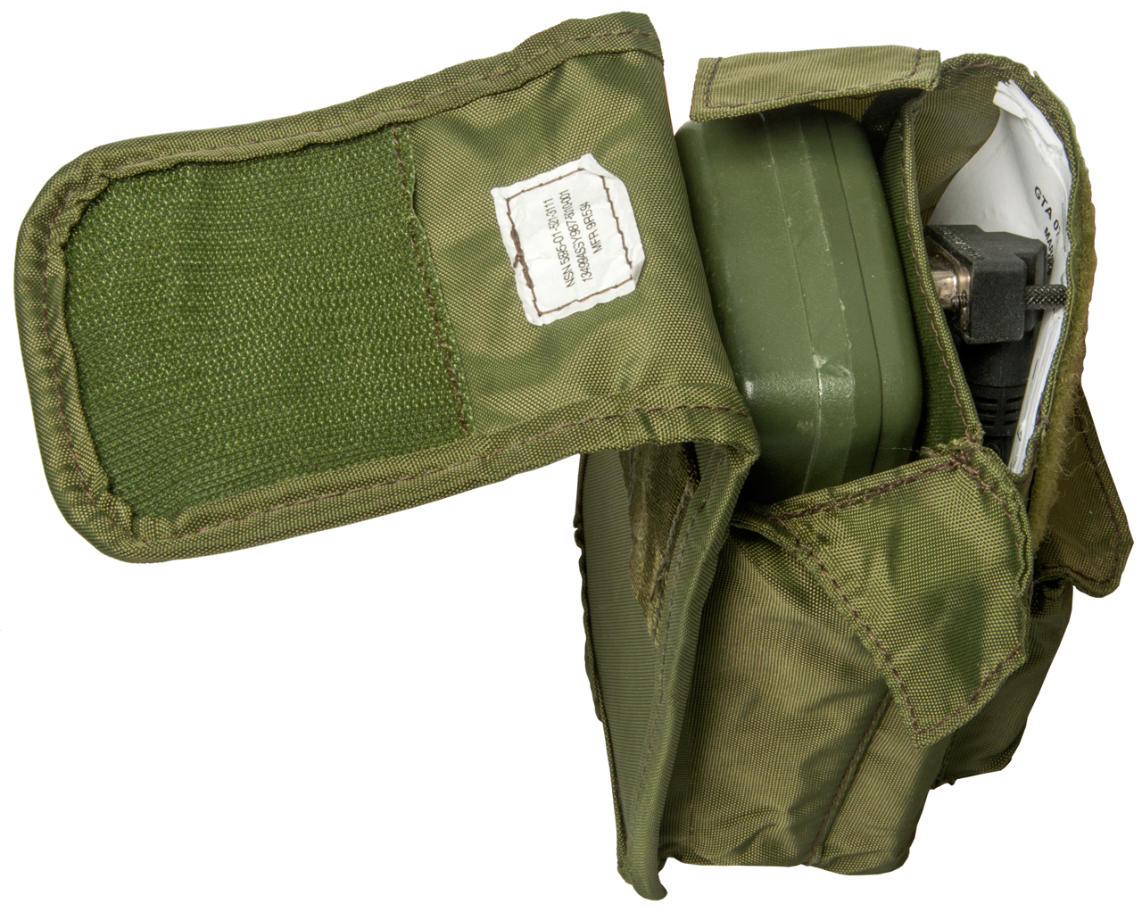


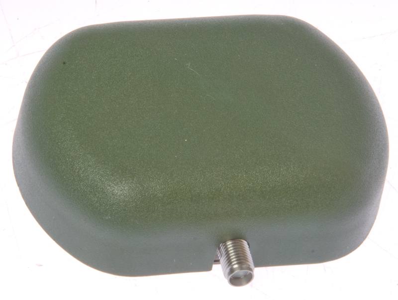


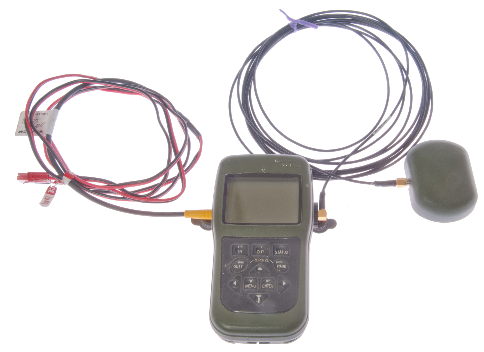

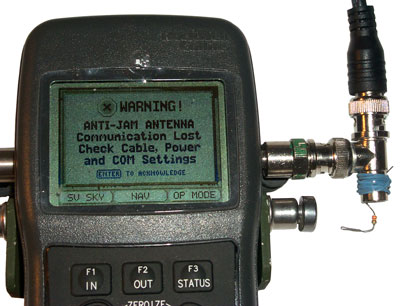
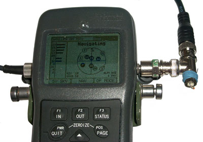
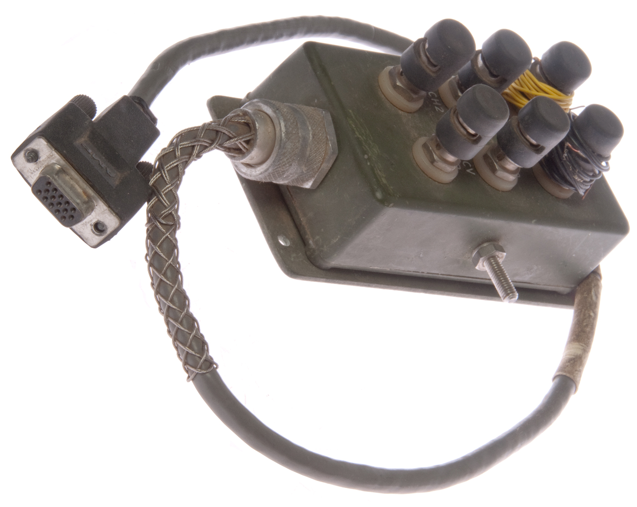

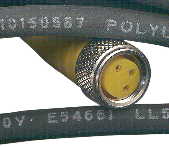
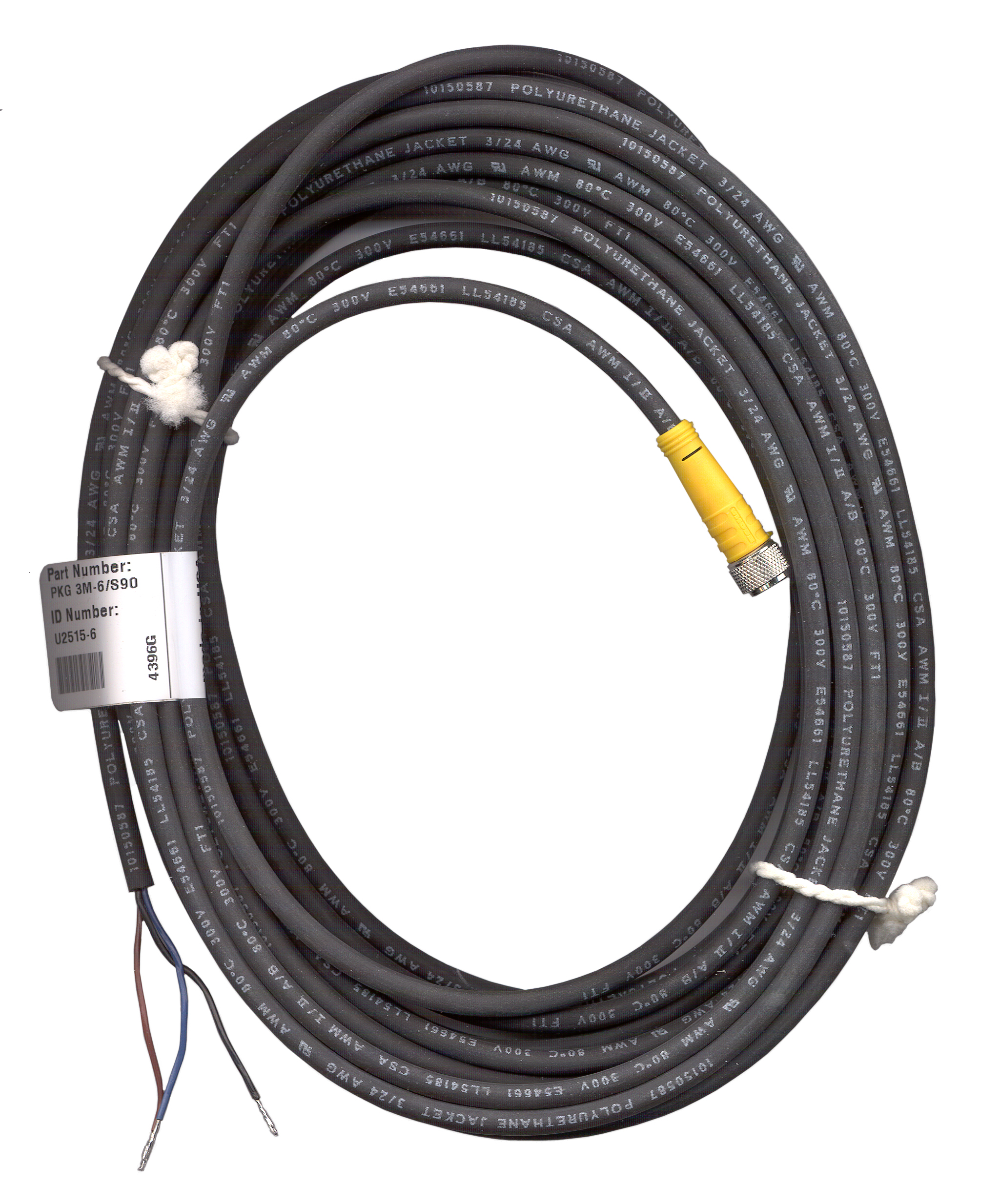

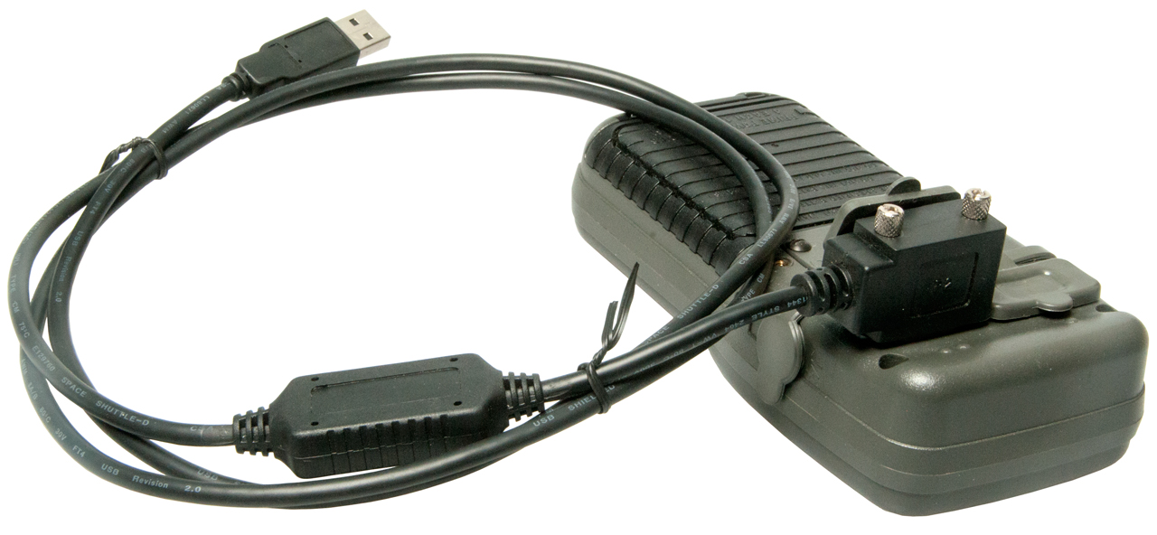
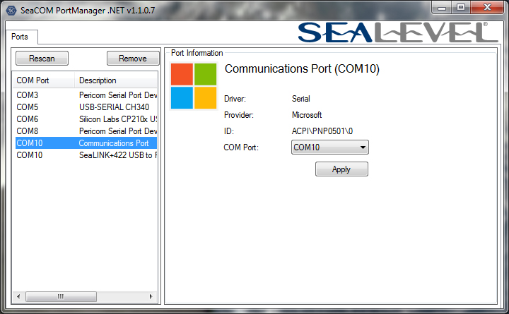
For precision munitions how about pattern matching TV guidance, i.e. AGM-62 Walleye?
Note both of these are old technologies and would work much better using modern techniques.
PS There are very modern devices that can see stars during the day that could be used for Celestial Nav.