Antennas
©Brooke Clarke,
N6GCE 2001 - 2025
General Information
Trade-offs
VLF Antennas
General
AS-3379 Buoyant Cable Antenna
(BCA)
HF Antennas
Long Range
Medium Range
Ground
Conductivity
Dipoles
& Wires
Whips
A-98
Phantom Antenna
Harris
RF-3134 HF Loop
Tecsun AN-100 AM Loop
Curtain
VHF Low Band Antennas
Mast Mounted
OE-303 1/2 Rhombic, 2 - 35 MHz
OE-254 Bi-conical 30 - 88 MHz
RC-292 1/4 Wave with sloping ground plane,
20 - 76 MHz
Create Discone 20 - 1 GHz?
Crate Log Periodic 20 - 1 GHz?
SORAK 2 - 76 MHz
Diamond D-130 Discone Rx: 25 - 1300 MHz; Tx: 50, 144, 430, 904, 1200 MHz
Mobile Mounts
Hand Held
Man Pack
Field
Body
VHF High Band Antennas
UHF Antennas
Microwave
Direction Finding
Sleeve Monopole
Receiving Loops
Other DF
Antenna Theory
Masts
Antenna Related
Supports
Pre-Amplifiers
Antenna Tuners
Antenna Couplers
Antenna multicouplers
Duplexer
Time Delay Beam
Steering
Counterpoise
Pattern
Patents
Related
Links
General Information
The antenna used for either receiving or transmitting is
a vital element in the communication link. In most cases the
antenna has a great deal to do with how well the receiver or
transmitter works.
Antennas are reciprocal, meaning that an antenna designed for
transmitting will work for receiving. A passive receiving
antenna will also work for transmitting. BUT the goals are
different for reception and transmission. In general a
receiving antenna should provide a good signal to noise
ratio. In general a transmitting antenna should radiate
energy as efficiently as possible in the direction of the
receiver. A loop may make a great receiving antenna for a
broadcast band radio but would be terrible as a transmitting
antenna. Transmitting into an active receive antenna will
let the smoke out of it.
Trade-offs
You can have small size, wide bandwidth, high efficiency,
choose any two.
Size
|
Efficiency
|
Bandwidth
|
Design
|
Small
|
Low
|
Narrow
|
Magnetic Loop
|
| Small |
Low |
Wide
|
|
| Small |
Hi
|
Narrow |
|
| Small |
Hi |
Wide
|
|
Large
|
Low |
Narrow |
|
| Large |
Low |
Wide
|
|
| Large |
Hi |
Narrow |
|
| Large |
Hi |
Wide |
|
VLF Antennas
By far the best performing low frequency antenna I've used is a
long wire (say 100 feet) in series with a variable inductor
(Miller 3 mH).
General
McKay Dymec DA-100 Active Whip - Board
Layout & Circuit Diagram
- through 30 MHz coverage
McKay Dymec DA7 Loop
AMRAD - Active Low Frequency Antenna has
coverage to 30 MHz
AS-2108/ARN-89 crossed active loops for
chopper radio direction finding
Light Weight Beacon - a 50 foot tall
antenna system that fits in a back back along with a transmitter
Home Brew Loopstick for WWVB - work in
progress, not working yet
2019 SLAC - New VLF Tx antenna
US20190074578A1
Piezoelectric Transmitter, Matthew
A. Franzi, Erik
N. Jongewaard, Mark A.
Kemp, Emilio
A. Nanni, Leland
Stanford Junior University, 2019-03-07 - resonance peaks at 35.475 kHz
and 35.500 kHz (25 Hz FSK).
US20190097119A1
Piezoelectric Transmitter - looks the same as above
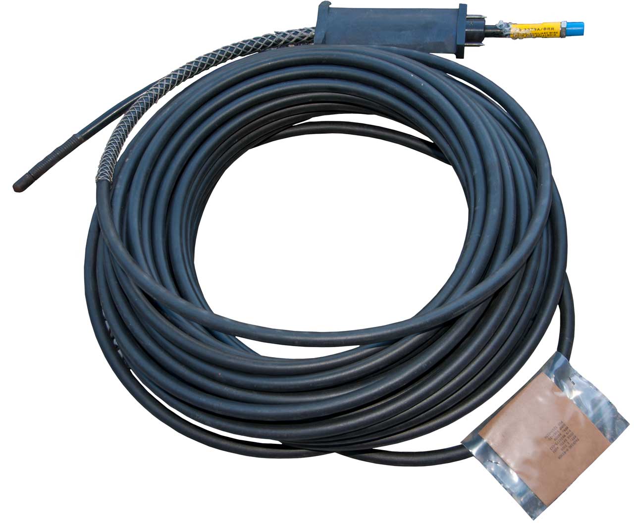
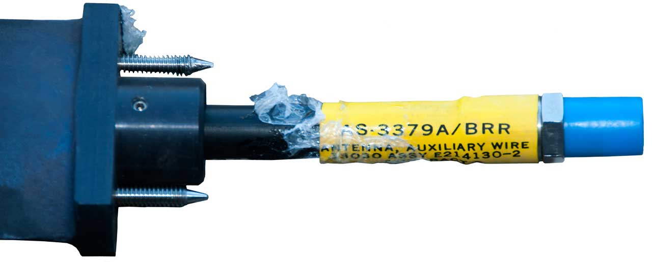
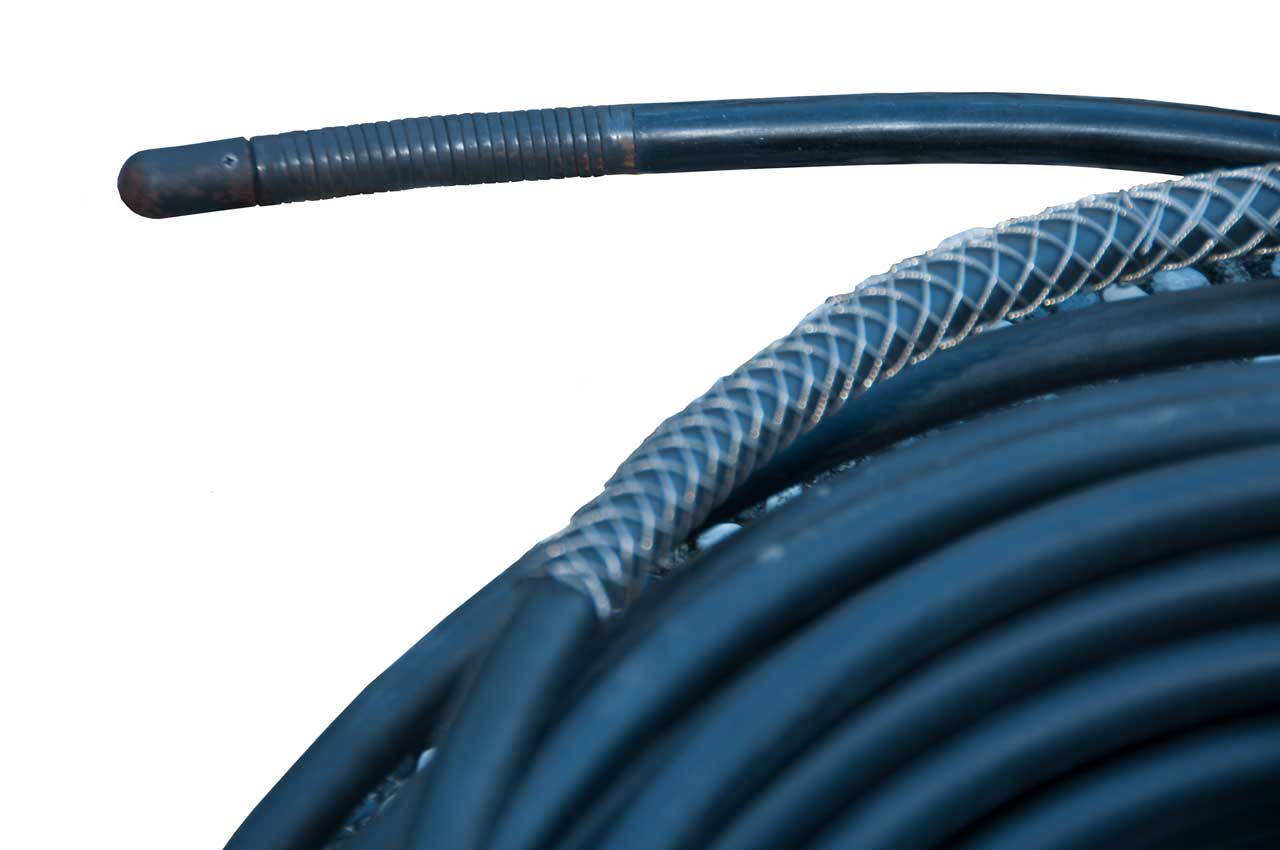
AS-3379A/BRR Antenna, Auxiliary Wire,
Buoyant Cable Antenna (BCA)
Fair Radio
has been offering these for many years and Google returns no
information at all.
"WIRE-CABLE ANTENNA probably towed behind ships or submarines as
VLF-LF antenna. Consists of 125 foot long 5/8" dia coaxial cable
with 8"L cast aluminum mounting shank and special RF connector
which could probably be changed to common N or C connector.
Suitable also for under or above ground use. No further info; 23
lbs."
Weight of saltwater = 63.9 pounds/cu ft *125' *( 0.3067 sq
in/144 in/sq ft) = 17 pounds. So might float or have
neutral buoyancy?
2067337
Antenna for submarines, Polatzek
Max, Telefunken
AG, 1937-01-12, - hose inflated with compressed air with
wire along axis.
3599213
Flexible bouyant cable antenna, Dennis
E Fessenden, Michael
A Tucchio, Luason
L Carnaghan, Navy,
1971-08-10, -
7468703
Buoyant cable antenna system, Erich
M. Gerhard, Navy,
2008-12-23, -
Maybe AS-3379
The antenna is about 100 feet long -then- the in-line
amplifier -then- either 850 or 1900 feet of cable to
sub.
4774519
Towable buoyant cable antenna system with in-line
broadband amplifier, Brian
L. Pease, Raymond
J. Phillips, Anthony
R. Susi, Navy,
1988-09-27, -
Citations
3662260
Electric field measuring instrument with probe for
sensing three orthogonal components, Aubrey
M Thomas, Aubrey
G Holston, Navy,
1972-05-09, - combine signals from 3 orthogonal active
whip antennas into total mag and direction.
4376941
Antenna cable, Joseph
A. Zenel, Navy, 1983-03-15, - distributed ELF loop
antenna (<10 kHz)
4463358
Convertible termination tip for submarine buoyant cable
antenna system, Raymond
J. Phillips, Navy,
1984-07-31, - either open or short.
H1220
VLF-VHF broadband in line amplifier for submarine
antennas, Brian
L. Pease, Navy,
1993-08-03, -
10 kHz to 160 MHz [VLF: 3 - 30 kHz, LF: 30 - 300 kHz, MF:
300 kHz - 3 MHz, HF 3 - 30 MHz & VHF: 30 - 300 MHz]
Citations
4760348
Broadband in-line amplifier for submarine antennas, Brian L.
Pease, Raymond
J. Phillips, Anthony
R. Susi, Navy,
1988-07-26, -
Citations: US3805164A, US3965426A, NL8105622A, US4531234A
Cited By:
H1588
Helical spring fastener, David
V. Arney, Navy,
1996-09-03, - a helical spring can be threaded over
one end.
20070146077
Radio frequency power amplifier, - maybe IC or hybrid
20100045545
Ultra WideBand buoyant cable antenna element, David
A. Tonn, USA,
App: 2008-08-20, Pub:2011-01-11, - open frame L-C
design for wider bandwidth.
20110051555
System and Method for Determining Location of
Submerged Submersible Vehicle, James
B. Mitchell, Bliss
G. Carkhuff, Morris
L. London, Robert
E. Ball, Nathaniel
J. Hundley, Johns
Hopkins U, 2012-10-16, - dead reaconing combined
with radio fixes?
20110279336
Modular VLF/LF And HF Buoyant Cable Antenna And
Method, David
A Tonn, USA,
2012-06-19, - combines LF/VLF antenna as capacitance
coupled coax feeding HF coax antenna.
|
Some info on Sub antennas is at: Section
4 Submarine Antennas -
Band
|
Systems
|
|
HF
|
BRA-6B, BRA-34, OE-207/BR, BST-1, OE-315,
BRR-6, Type 18 Periscope
|
|
LF - VLF
|
OE-315 , BRA-34, OE-207, BRR-6, Type 18
Periscope
|
|
ELF
|
OE-315
|
|
Navsea
letter of 2 July 2008 offering patent rights to a family of
Buoyant Cable Antennas (BCA), inventor
7466278
BUOYANT CABLE ANTENNA SYSTEM AND METHOD WITH ARTICULATING
BLOCKS, Erich M. Gerhard
7411558
BUOYANT CABLE ANTENNA CONFIGURATION AND SYSTEM
7952530
SERPENTINE BUOYANT CABLE ANTENNA SYSTEM
Prior Art:
5933117
Flexible ferrite loaded loop antenna assembly - Buoyant Loop
Antenna with Ferrite beads "provides an omni-directional cable
antenna assembly for VLF/LF frequency ranges"
4978966
Carborne Antenna - rod shaped cores end-to-end to fit on a car
2428480
Buoyant electric cable - helix over closed compartments
3117596
Buoyant flexible hose - air filled hose antenna
3823249
compressed gas insulated for HV
Monterey NPS Thesis: Common
Submarine Radio Room: A case study of a system of systems
approach, Seime, 2014
NAVSHIPS 900,121 (A) Antenna Systems; Section 6-3 Submarine
Antenna Systems
BLR-1 system - ECM stub antenna, Omni Antenna, AS-626
Alford DF experimental
BPA-2, BPS-1, BPS-2 Radar
BPS-4 IFF
BRD-3 DF (UG-941 & RG-14 coax limits frequency) R-566
receiver, AS-655 Antenna
RAK receiver uses NT-66097 loop antenna
SRR-11 (RAK or RBA) receiver, CU-941 VLF coupler, AT-317/BRR
teardrop antenna
TDZ transmitter, RDZ receiver, CU-274 coupler, RG-14 coax,
AS-468 antenna.
NAVSHIPS 94200
BRA-1 Antenna Coupler Group, 300 Watts, 15 kHz to 26
MHz
BRA-13 Antenna Tuning Group, 1000 Watts, 2 to 30 MHz
BRA-3 Antenna Tuning Group, 500 Watts, 2 - 26 MHz
BRA-5 Antenna Tuning Group, 500 Watts, 2 - 26 MHz
BRA-6 Antenna Tuning Group, 750 Watts AM, 2 - 6 Mhz
Antenna Catalog Vol III, Oct 1960
AS-371 - 1 to 4 GHz conical (receivers: SPR-2 or
BLR-1)
AS-393 - 1.8 to 3.6 GHz
AS-468 - 225 - 390 MHz, vertical polarization
AS-493 - Triple Antennas: 2.88 GHz , 465-510 MHz, 225 - 390 MHz
- Wiki: AEW
- 2.88GHz is a frequency assigned to
the US gov., maybe radar?
AS-524, AS-525, AS-535 - 110 - 156 MHz VHF AM air band
AS-658 - 225 - 400 MHz Adcock DF antenna URD-4
AS-949 - Triple Antenna: 2 - 30 Mhz, 30 - 400 MHz, 950-1200 MHz
-
AS-996 - 8.74 - 8.89 GHz, BPS-9 search Radar
AS-1014 - MultiBand: MF, HF, UHF, IFF
AT-151 - 3.8 - 5.0 GHz, SPM-1 cal Tx for DBM-1 DF
AT-274 - 14.6 - 38 kHz, single loop, laminated core, 500 uH, 70
pounds,
AT-317 - 14.6 - 38 kHz, dual crossed loops, RAK, RBA, SRR-11
AT-343 - 2 - 26 MHz, Whip
AT-350 - 2 to 30 MHz, Whip
AT-365 - 30 to 1,000 MHz, SPR-1 Radar & BLR-1
Countermeasures
AT-693 - 30 to 1,000 MHz, BLR-1
AT-774 - 2 to 30 MHz, C-clamp whip for emergency use
AT-818 - 2 to 30 Mhz, Whip,
66AAP, 66ADH - 2.965 - 3.019 GHz, SJ Fire Control Radar
66AFU - 157 - 187 MHz, BN early IFF
66AGO - 100 to 1,000 MHz, DXA DF
66016 - 60 to 80 MHz, TBS radio
66097 - 15 to 77.5 kHz, Loop, 143 pounds, RAK radio, solid
mounted, turn sub for bearing
66142 - 1 to 5 GHz, 0 to 150 RPM, DBM-1 DF
HF Antennas (2 to 30 MHz)
The key idea about HF radio is the propagation by reflection
from the ionosphere. Frequencies below 2 MHz or above 30
MHz can not reflect off the ionosphere.
Although you can use HF to cover short distances without the
ionosphere, called ground wave propagation (Wiki)
which works well for lower frequencies, it is very poor method
at HF.
Successful HF propagation depends on reflecting the signal from
the ionosphere. There are two common methods of doing
that.
Long Range
In this mode a signal can goo all
the way around the Earth (and sometimes has been seen to make
multiple revolutions) so can cover great distances.
See the Very Basic Antenna Information at the top of my
HF Propagation web page to help
understand propagation modes and which antenna type supports them.
A common antenna would be a half wave dipole mounted 1/2 wave
above a perfectly conducting surface. If the dirt under the
dipole is not very conductive then it could be lower and work
well. The idea is that the main lobe is broadside to the wire and
covers horizon to horizon including straight up. Note for a
perfect antenna there are nulls off each end where there's no
propagation. This is what's called a DX antenna.
Medium Range
I'm using the word medium to differentiate between line of sight
which I would call short range. Near Vertical Incidence
Skywave (
Wiki
NVIS) is a term coined during the Vietnam ear for the idea of
aiming an HF signal directly overhead so that when it reflects
from the ionosphere if comes back down to Earth an illuminates a
circle that's 500km (300 miles) in radius. But this mode of
operation has been used long before Vietnam, it just didn't have
that name.
A common antenna would be a half wave dipole mounted 1/4 wave
above a perfectly conducting surface. If the dirt under the
dipole is not very conductive then it could be lower and work
well. The idea is that the main lobe goes straight up and
there are nulls at the horizon in all directions. This
provides higher gain than the DX dipole described above because
the power is more confined in where it can go. (PS.
antenna gain and antenna pattern are a function of each
other. For example you can not have an omni
directional antenna with high gain).
If the antenna is lowered there are two effects:
1) the received noise level is decreased, and
2) the transmitted signal level is decreased.
So lowering below 1/4 improves reception, but degrades
transmission.
See my
AS-2259 Antenna web page for
more on NVIS
DA-100 Active Whip &
DA-7 BCB indoor loop
Harris RF-1944 comes in three versions:
AT020
(20 Watt),
AT150
(150 Watt) and AT400 (400Watt). Inverted V configuration.
Comrod
HF230L-B HF 1-30MHz Loop (
pdf)
- used on the M142 HIMARS (
Wiki) &
M270 MLRS (
Wiki).
Ground Conductivity
This has a stronger effect on NVIS antenna than it does on DX
antennas, but still is important for DX. Note that in the
days prior to satellite communications the long range HF radio
stations were located very close to the edge of salt water where
the ground conductivity was low. The 1/4 wave vertical
antenna towers used for AM radio transmission typically have 120
radial wires so that the ground conductivity is controlled.
In English we have different meanings for "ground" (Wiki).
One meaning is dirt another meaning is an electrical
terminal. In the case of the "ground" under an NVIS
antenna the operative definition is electrical terminal (not
dirt). So it's not a simple matter to determine how high
above ground you are mounting the antenna. In the desert
where sand is an electrical insulator a buried NVIS antenna may
work great but an NVIS antenna a foot or two above fertile
agricultural soil may not work at all. I suspect there are
simple methods of measuring the resistance of the soil maybe
just using a DMM in the Ohms mode or
using a 4-point probe (Wiki: 4-Point
Probe, Volume
Resistivity)made from a 2x4 and some long nails. But
there's probably a frequency dependance of the soil resistance
making the measurement much more complex.
The B&W Broadband Folded Dipole
Antennas (ASW-90)
U.S. Patent 4423423
is
an excellent receiving antenna for broad band signals like chirp sounders. This design is
also called a T2FD (Wiki).
The efficiency for transmission goes down rapidly below 40
meters. Works far better than any active whip or loop.
I had one of these for many years, but a storm took down one of
the trees holding it up.
4423423
Broad bandwidth folded dipole antenna, Elmer
R. Bush, Baker
& Williamson, 1983-12-27, -
1974387
Antenna, Carter
Philip Staats, RCA,
1934-09-18, - half rhombic, bow tie,
3757341
Long wire v-antenna system, A
Gilbo, Sanders
Assoc, 1973-09-04, - Slopping Rhombic, Wullenweber (Wiki)
precursor
OE-452 - NSN 5985-01-279-7942, Special Operations Radio Antenna
Kit SORAK
AS-2360 Loop Antenna Parts List &
Radio Receiving Set AN/TRQ-23 Antenna
Group OE-4/GR AS-2360 Series Loop Antennas
AS-2259 or AS-2268 (Collins 637K) NVIS
tactical antenna
GRA-50 1.5 to 20 Mhz Reel dipole where
the reels are at the far ends, not the center. HF NVIS Dipole
w/reels at the ends
AS-1321/PRC-47
Antenna 45 foot long wire
AT-984/G 150 foot wire
Eyring Low Profile Antenna 301A (ELPA
301A)
Hy-Gain HA-4000,
18TD, Collins TD-1, 637T-2 - a dipole made with two steel tape
measures as the center part. You pull out the tapes, marked
in the metric system and you're good to go
 |
637T-2 has two reels with antenna wire on each.
Center support hole on top and type N(f) connector on the
bottom. Used to quickly and easily make a dipole for
NVIS ops.
|
SORAK - HF & VHF low band
configurations
TCI 651T crossed delta
loops
Whips
AS-1320/PRC-47 Antenna 15 foot whip
GRC-106 15 foot whip -photo - in CW-206 bag - Fair was
selling these as a GRA-50, but they are for some transmitting
application because of the insulating sleeve for the lower whip
(ms-11x whip sections. Not the receive only antenna for the
R-442.)
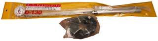
AT-271 Fishing Pole 3 meter
AT-1011 Shakespeare 120 HF antenna
system 12, 16 or 32 foot whip
Eyring Low Profile Antenna 301A (ELPA
301A) can be buried 1 foot deep
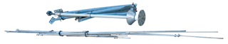
TCI 651T -HF portable
antenna, single mast
M-442 Adapter

|
Accepts AB-21 or MS-116 tubular antenna elements and has
common 3/8-24 male thread to fit the PRC-104,
AB-591, etc.
got this one from Fair Radio
|
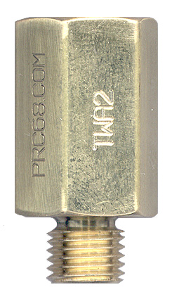
Tape Whip Adapter
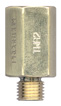
|
Accepts 5/16-24 male thread on mil antennas and screws
into 3/8-24 ham, CB, commercial antenna bases. The
5/16-24 female thread is deep enough to allow the AB-591 antenna base to be used.
|
Ship's Goniometer NUS-883
- photo - Adcock Antenna
(Wiki)
array for mounting on ship's mast
|
PRD-1
Loop
|
The PRD-1 receiver uses a single turn diamond shaped loop
made of tubing.
|
A-98 Phantom Antenna
This is a small box that contains a series connected 700 pF
capacitor and a 31 Ohm resistor. Designed to work with the
Gibson
Girl SCR-578.
Note phantom antenna for a full size dipole (Wiki)
would just be a 73 Ohm resistor and for a 1/4 wave vertical
would be a 36 Ohm resistor. Since the antennas issued with
the Gibson Girl are not full size the phantom antenna uses a
little less resistance and some capacitance.
Harris calls it On The Move (OTM). These show up on the
HIMARS (Wiki) in
Ukraine.
20110273354
Transfer Unit for Radio Frequency Signals and Method for
Alternatively Using an Electrical Antenna or a Magnetic Antenna
with a Classic Antenna Tuner, Ronald
Davidson, Comrod,
2015-03-17, - Comrod
HF230L-OTM.pdf, 8 hole NATO bolt pattern. Base unit
contains inductor and switched caps.
Following patents cited in body of Davidson patent
both use series L and shunt C to match between antenna and radio
and so are not suitable for magnetic Tx loops.
3794941
Automatic antenna impedance tuner including digital control
circuits, L
Templin, Hughes
(Raytheon), 1974-02-26, - 2 to 80 MHz (cited
by 142 patents)
5589844
Automatic antenna tuner for low-cost mobile radio, Donald
K. Belcher, David
C. Bailey, Flash
Communications, 1996-12-31, - for matching the whip on a
vehicle. Pi network. uC used to develop calibration
table.
The following patent uses a series cap but in a complex (costly)
way. Also this patent claims an upper frequency limit of
15 Mhz (B.C.: For NVIS this is OK). The Davidson patent
works to 30 MHz but that added coverage is not going to help
NVIS coms, but may help ground wave coms?
5072233
Loop antenna with integral tuning capacitor, Gary
R. Zanzig, 1991-12-10, -
Tecsun AN-100
AM Loop
Fig 1

|
This is a Chinese knock-off of the Tecsun
AN-100 Tunable Medium Wave Loop Antenna.
There are two coils wound on a 23cm diameter plastic tube
using 0.8mm wire.
Main Coil
355 uH, 0.87 Ohms
Resonated with a variable capacitor of about 10 to 280 pF.
Pickup Coil
6.3 uH, 0.01 Ohms.
The supplied cable has bare wire ends for the radio
connection and a 3.5mm Stereo plug to connect to the
antenna.
The pickup coil is connected to Tip and
Ground/Sleeve. The Ring is not connected.
|
The AN-200 has a different base that may be a lot harder to
open.
Curtain
Curtain Arrays (Wiki) a
class of antennas that resemble a curtain suspended on a
cable. The idea is by combining a number of antenna
elements a very directional beam can be formed, both in azimuth
and elevation.
The Sterba antenna (Wiki)
"...modest-gain single-band" was replaced by the HRS antenna (Wiki)
"... Horizontal
dipoles with a Reflector behind them, and the beam
is Steerable"
|
1813143
Aerial system, Bruce
Edmond, Bell
Labs, 1931-07-07, -
|
|
1885151
Directive antenna system, Ernest J Sterbam, Bell
Labs, 1932-11-01, -
|
|
2622198
Phased antenna array, Richard
G Clapp, Samuel
H Colodny, Wise
Bernard, Philco
Ford, 1952-12-16, -
|
|
|
30 - 90 MHz
Line Of Sight
The range between a standing
manpack and a manpack lying on the ground is about 2.7
miles. Between two standing manpacks it's about 5.4 miles.
Antenna elevation is the key factor for this band. Power
is not that important. Most radios have a few watts of
output power and that's all that's needed for normal links.
Mast Mounted
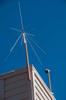
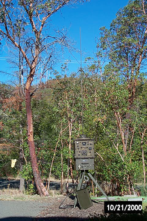
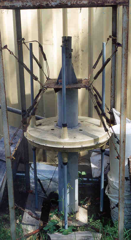
RC-292 1/4 Wave Vertical
Create Discone
- this makes a great scanner receive antenna when a Radio
Shack 15-1170
amplifier is used.
Shown disassembled with roof mount tripod.
Maybe 20 MHz to 1 GHz?
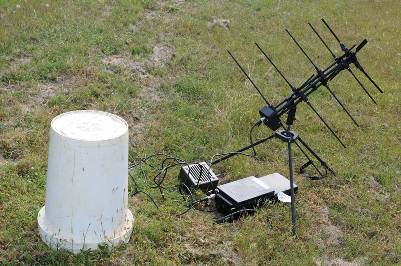
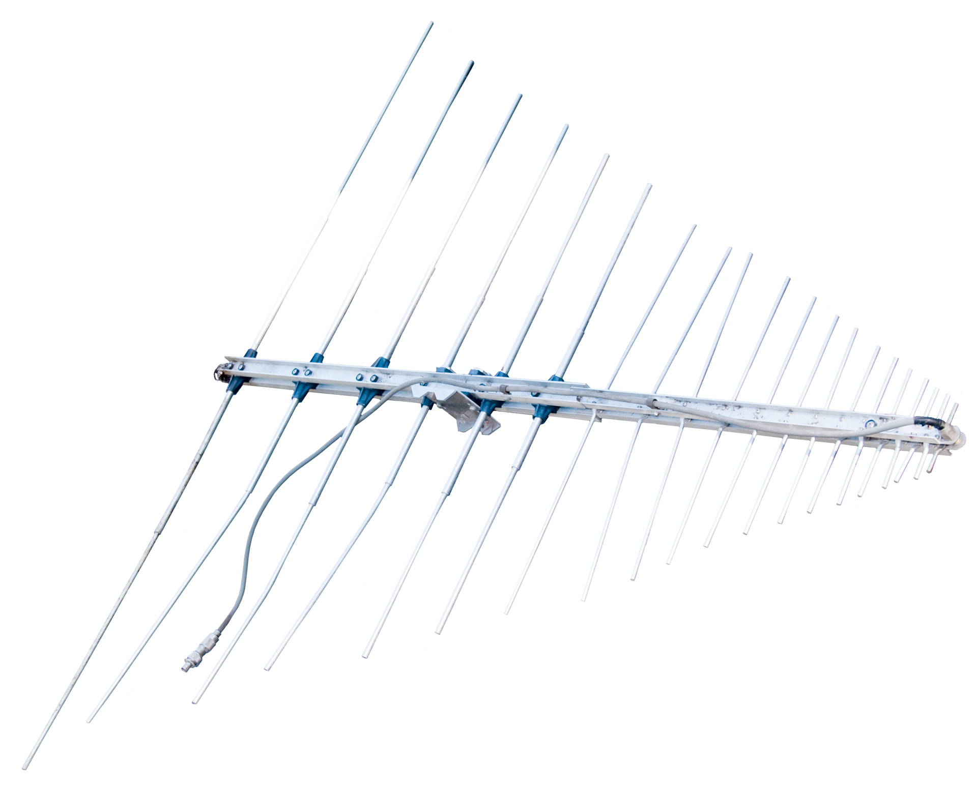
Create Log Periodic
Maybe 20 MHz to 1 GHz?

SORAK - HF & VHF low band
configurations
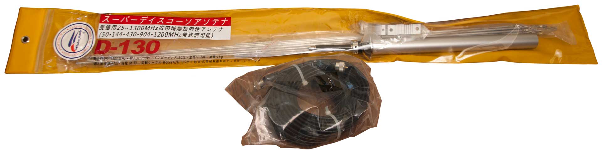
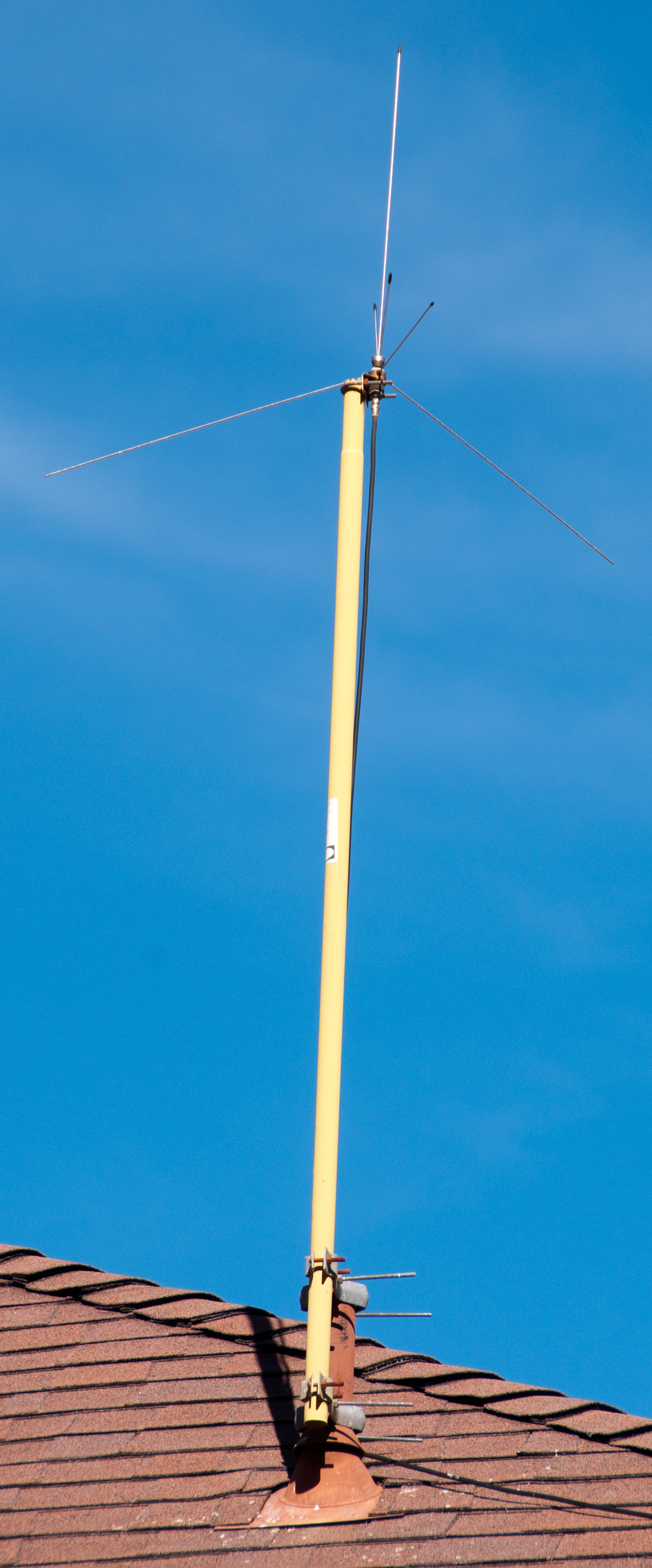
Diamond
D-130 Super Discone Antenna
2020 Aug - Designed for both wide band reception (25 - 1300
MHz) and transmitting on ham bands (50, 144, 430, 904, 1200
MHz) so will work with the Agilent
E4404B Spectrum Analyzer, and VHF/UHF ham radios (ICOM 706, UV5B,
Yaesu VX-7). This is a much more
compact and easier to erect antenna than the Create
Discone. A key feature is that the coax is protected
from the weather be being inside the support tube, see Fig 3
below.
Fig 1 Using RG-8x instead of RG-58.
If I would have seen it sooner I would have bought the D-130NJ
with Type-N connectors.
|
Fig 2
 |
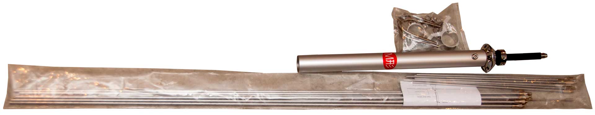
Fig 3 The coax needs to be installed
early in the assembly process, otherwise it may be
difficult to access.
The mounting brackets should also be installed now.
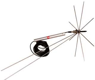 |
Fig 4
 |
Fig 5 bottom of radials more than 6"
above metal cap on chimney.
GPS antenna in background. Bracket for DA-100 Active Whip just
visible.
 |
Mobile Mounts
AS-1729 Remote tuned
vertical dipole (MX-6707)
Hand Held
AT-784/PRC directional Loop
Rubber Duck - used on PRC-68 family of Squad Radios (Note: this
antenna has 30 dB less radiated power than the AT-892 on a
PRC-68!, that's NOT a typo)
AT-892 Tape - used on PRC-68 family of Squad Radios
68AA Antenna Adapter - fits the
special PRC-68 family of hand held squad radios and has a
standard BNC(f) connector plus a DC return to the more modern
radios in the family will correctly know an external 50 Ohm
antenna is connected.
Man Pack Radio
Mounted
AT-271 3 meter fishing pole
used with the AB-591 spring base
AS-2109 Telescoping that can act as
either a 1 meter or 3 meter antenna for the PRC-25, PRC-77 etc.
Shortened Antennas for Portables by
Dennis Starks
Field
AT-984/G Fishing Reel 150
foot wire used for HF and VHF antennas
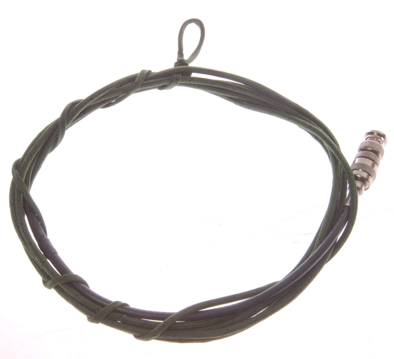
Body
Soldiers carrying an antenna are high on the enemies target
list so they typically do not unfold the antenna which means
the radio barley works if at all. So I've read that an
antenna was developed to be wrapped on the body of the soldier
carrying a radio so as to not have an easily visible
antenna. I think that's what this is, but there are no
markings. It has a TNC-m connector so not sure which
radio it fits, maybe it is not a VHF low band antenna, TBD.
The 50? Ohm line from the connector to the antenna is about 9"
long. The antenna is about 100 inches (2.5 meters)
long. The lanyard is about 19" long.
If you know about it please contact
me.
None of the below seem to match this antenna. Maybe it
was a prototype that didn't work?
The COMWIN Antenna Project (slides).
7471258
Coaxial cable having high
radiation efficiency, Hrl
Laboratories, Llc, Dec 30, 2008, -
7956818
Leaky
coaxial cable with high radiation efficiency, Hrl
Laboratories, Llc, Jun 7, 2011, -
8059045
Antenna having an impedance
matching section for integration into apparel, Hrl
Laboratories, Llc, Nov 15, 2011, -
9209514
Body-worn antenna,
Motorola
Solutions, Inc., Dec 8,
2015, - aimed at undercover police work - concern for RF
exposure
VHF High Band Antennas
108 - 170 MHz
Eggbeater - has a
circularly polarized pattern going up which is good for working
satellites and has vertical polarization in the direction of the
horizon which is good for working most VHF stations. See Brooke's Military Information/Equipment
for more on this one.
AS-3588/GRC-206 Combined VHF-AM &
UHF-AM Antenna for GRC-206 (PRC-104
page, MT-6250 page)
FM Radio - FM stations can use horizontal polarization to reach
receivers in stationary locations with indoor or outdoor
antennas. They can also use vertical polarization to reach
automobile whip antennas. Most stations divide their power
between the two depending on their target audience, commuters,
at work, commercial use, etc. A vertical antenna may work
better at your home if the station you want to hear is targeting
commuters.
Radio Shack 20-176 Scanner 1/4 wave (this model is obsolete,
replaced by the Model #: 20-043)

UHF Antennas
This is the military 200 (or 225) to 400 MHz band used by aircraft in the AM mode, for
Line Of Sight (LOS) communications by ground troops, and used for
linking to satellites.
AS-390A/SRC has ground
radials for pole mounting and painted navy grey, like for a ship
or control tower.
2483240
Antenna system, John
P Shanklin, Bendix
Aviation Corp, App: 1945-09-07, Pub: 1949-09-27, -
AS-1405/PRC-41 Log Periodic
AT-803/VR has same antenna element
as AS-390A/SRC but is intended for mounting to a metal shelter
roof (OD paint). mentioned in FM 24-24 as part of the VRC-24
& TRC-68 systems.
Satcom antennas
Trivec-Avant AV 2095 UHF Satcom
Antenna System - Gyroscope
stabilized.
LST-5 Satcom Radio with D&M C152-1-1
Antenna
Microwave
Satellite
When it was discovered that the cable companies were
getting their programming by means of C-band (3.7 to 4.2 GHz
downlink) receivers there was a move to make home brew
systems. The cost of a parabolic dish goes up as some power
of the diameter. The cost of a low noise amplifier goes up
as some function of how low its noise figure is. When the
sum of the antenna cost and the low noise amplifier cost are
plotted the curve has a sweet spot. Over time the sweet spot
has moved in the direction of smaller diameter antennas and better
low noise amplifiers.
The best F/D (focal length of the antenna divided by it's
diameter) for a parabolic antenna to have maximum gain is about
0.45, so most TVRO antennas were built with this rather flat
shape. The best G/T (gain divided by noise) is at an F/D
of 0.3. This is really the key specification since what
the receiver wants is the best possible G/T. I got one of
the antennas from Stanford used for a study of the Sun (they had
16 in a N-S line and 16 in an E-W line all phase matched feeding
a common receiver and all driven in hour angle to track the
Sun. These were spun Aluminum with an F/D of 0.3.
The feed was modified by an engineer working at Lockheed in
Sunnyvale (government satellites) from a classical horn feed to
what I call a nozzle feed that had matched E and H plane
radiation. This antenna out performed many commercial
units with diameters up to 16 feet. It used a WR-284
waveguide "button Hook" feed rather than use rods to support
another type of feed. It had only one polarization.
At first all the TVRO satellites used Vertical
polarization. Soon someone figured out that they could get
twice as many satellites in the same angular space if the
polarization alternated from horizontal to vertical. The
cross polarized signal is down 20 or more dB depending on the
quality of the antenna systems. Today this is still done
on the Ku band TVRO 18 inch dishes. It's too bad that they
did not change over to circular polarization for the Ku band
systems. That would make VSAT type uplinks much easier to
do since the "cross pol" adjustment would go away.
I worked on some of the microwave parts used in these
systems. They used four cavity backed spiral antennas on
each corner of an aircraft, each feeding a multicoupler with 3 or
4 outputs, each exclusively covering a different radar threat
frequency and on each of these outputs was a Limiter-Detector that
I designed and oversaw the production of.
Spiral
Cavity backed spiral antennas (Wiki)
were common on airborne radar warning receivers.
2863145 Spiral slot antenna, Turner
Edwin M (Air Force), priority: Oct 19,
1955, pub: Dec 2, 1958, 343/767,
343/908, 343/895, 343/732
- 30 to 15,000 MHz
2947000 Beacon antenna using spiral, Kaiser
Jr Julius A, Marston
Arthur E, Jul 26, 1960, 343/895, 343/846
3717878 Spiral antenna, Mosko
J (US Navy), priority: Jan 31, 1968, Pub:
Feb 20, 1973, 343/895 - a lower
frequency in smaller package
4559539
Spiral antenna deformed to receive another antenna, Raymond
S. Markowitz, Baruch
Even-Or, Walter
Bohlman, AEL, 1985-12-17, 343/725; 343/895 - to replace prior art 2 - 18 GHz
spiral antennas with 2 - 100 Ghz model.
Publication
number Priority date Publication date Assignee Title
US2856605A *1958-01-15
1958-10-14 Erling R Jacobsen Antenna
US2953781A *1959-11-30
1960-09-20 John R Donnellan Polarization diversity with
flat spiral antennas
US2958081A *1959-06-30
1960-10-25 Univ Illinois Unidirectional broadband
antenna comprising modified balanced equiangular spiral
US2977594A *1958-08-14
1961-03-28 Arthur E Marston Spiral doublet antenna
US2990548A *1959-02-26
1961-06-27 Westinghouse Electric Corp Spiral antenna
apparatus for electronic scanning and beam position
control
US3017633A *1959-11-30
1962-01-16 Arthur E Marston Linearly polarized spiral
antenna system and feed system therefor
US3188643A *1960-12-29
1965-06-08 Univ Illinois Circularly polarized
omnidirectional cone mounted spiral antenna
US3257660A *1964-07-06
1966-06-21 Wilhelm A Schneider Antenna using end fire
elements, translatable or tiltable apart or together, to
control beam width
US3343089A *1965-10-04
1967-09-19 Motorola Inc Quarter wave low profile antenna
tuned to half wave resonance by stub; also including a
transistor driving stage
US3530486A *1968-11-22
1970-09-22 Hughes Aircraft Co Offset-wound spiral
antenna
US3681772A *1970-12-31
1972-08-01 Trw Inc Modulated arm width spiral antenna
US3683385A *1963-03-07
1972-08-08 Us Navy Direction finding antenna system
US3699452A *1969-04-18
1972-10-17 Hans Kolbe & Co Kg Active antenna
arrangement for a plurality of frequency ranges
US3713163A *1971-11-22
1973-01-23 Nasa Plural beam antenna
US3787871A *1971-03-03
1974-01-22 Us Navy Terminator for spiral antenna
DE2707819A1 *1976-02-23
1977-09-01 Motorola Inc Scroll members antenna
US4051481A *1975-01-29
1977-09-27 Abreu Joao Do Espirito Santo Helical band
antenna
GB1498364A *1976-02-25
1978-01-18 Fun Chan P Antenna
US4095230A *1977-06-06
1978-06-13 General Dynamics Corporation High accuracy
broadband antenna system
US4243993A *1979-11-13
1981-01-06 The Boeing Company Broadband center-fed
spiral antenna
US4319248A *1980-01-14
1982-03-09 American Electronic Laboratories, Inc.
Integrated spiral antenna-detector device
There are a number of ways to get a bearing to a signal:
Doppler - uses a rotating antenna element and measures the Doppler
shift
Pseudo Doppler - switches antenna elements to simulate a Doppler -
BM Engineering out
of business 1998-
patent
4,475,106 "High sensitivity portable radio direction finder"
Goniometer - rotating central commutator with multiple directional
antennas like in the Wullenweber
(Elephant Cage; Wiki: AN/FRD-10).
A Wide-Aperture HF Direction-Finder with Sleeve Antennas, Gleason
& Greene, NRL843, 1958 (ADA459666.pdf),
39 pages - 434' dia, 2 - 25 MHz (with 65' high cage height).
Project Boresight (Wiki)
was a way of using the Wullenweber to locate subs that were
sending burst transmissions (GRA-71). This made use of Magnetic
Recording with a time/date stamp that was very accurate.
See also:
NRL 746 A Wide-Aperture HF Direction Finder, Gleason & Greene
NRL 825 A VHF Elevated H-Adcock Direction-Finder, Gleason
NRL 830 Bearing Readout Systems for Goiometer Direction Finders,
Wald & Misner
ASRE 806 The Wullenweber, Mugridge & Redgment
NRL 832 An Inductively Coupled Goiometer for Wide-Aperture DF
Arrays Gleason & Johnson (ADA459667.pdf),
1958 -
Amateur
Radio
Direction Finding Web Ring -
IDA stands
for Information Dense Antenna - Roger Karlsson
- 6407702
Method
and system for obtaining direction of an electromagnetic wave
Loop antennas have a sharp null that can be used to get a bearing
that's either to or from the station. An Adcock (Wiki)
arrangement of verticals also has this null property.
Fenwick patented a time delay beam
steering system where the direction is frequency independent
unlike phased arrays where the beam angle is a function of
frequency.
Sleeve Monopole
The vertically polarized antennas used for the lower frequency
portion (2-6 & 6-9 Mhz) were sleeve Monopoles.
|
2704811
Cylindrical antenna, Andrew
W Walters, 1955-03-22, 98 - 298 MHz, includes design
ratios
|
|
5231412
Sleeved monopole antenna, John E. Eberhardt, Oscar M.
Garay, Yew S. Tay, Motorola,
1993-07-27, -
|
|
|
Receiving Loops
ARN-83 LF aircraft DF set
ARN-89 LF aircraft DF set
AT-339 VHF low band hand held DF loop for PRC-6, photo
AT-784/PRC directional Loop for use with PRC-25
DU-1 Loop Ant
and CRR-50001 Coupler Unit - Diagrams 1, 2, 3 & 4
MN-24C manual rotation aircraft loop - photo
-
PRD-1 HF DF set
Radio Receiving Set AN/TRQ-23 and
Antenna Group OE-4 DF set with
up to 150 RPM loop rotation
URM-6 Field Strength set 14 to 250 kHz
2251131
Radio compass loop construction, Jr Frederick
D Herbert, Kearfott
Engineering, 1941-07-29, - "... radio compass loop mountings
and more particularly to such mountings used on aircraft in
Zeppelin or tear-drop type of loop housing."
Other DF
Time Delay Beam Steering -
see below for antenna system for Rx & Tx
to a azimuth & elevation
Goniometer - This is a
Watson Watt (Adcock) array of 4 vertical dipole antennas designed
for use on a ship. Photo
Antenna
Goniometer
NUS-883 Serial 54-8
Federal Electric
Manufacturing, Co. Ltd.
Montreal, Canada
It is made to go on top of a mast with a 2" O.D.
It has 4 each vertical dipoles 50" end to end that are in a square
pattern 14" on a side.
A Type-N connector and a male 10-pin military connector.
There is a lamp at the top that I think is a 110 Volt unit.
I am
looking for more information about this Goniometer Contact me
also see my Electronics
web page.
Masts
AB-1386/U
The AB-1386 is a 10 meter telescopic Mast based on screw jack.
Will Burt model TM 10.
An eBay ad for "Will-Burt 10M Telescoping Mast, AB-1386/U" about
$900 + $150 shipping - drive motor -hand crank.
5163650
Telescoping mast with improved holddown-locking mechanism, Daniel
S. Adams, Gene
R. Butler, Kenneth
J. Pereira, Tri
Ex Tower (Will Burt Co), 1992-11-17, -screw
drive Quick Erecting Antenna Mast (QEAM)
5593129
Telescoping mast with improved holddown-locking mechanism, Daniel
S. Adams, Gene
R. Butler, Kenneth
J. Pereira, Tri
Ex Tower (Will Burt Co), 1997-01-14, - screw
drive Quick Erecting Antenna Mast (QEAM)
5615855
Telescoping mast with integral payload,
Edward A. Marue, Kenneth
J. Pereira, Tri
Ex Tower (Will Burt Co), 1997-04-01, - square cross section
tubes with antenna installed which nests inside tube. Spindle
driven.
Antenna Related
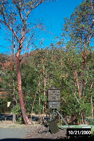
Supports
In many cases how well an antenna works depends more on it's
support than on the antenna proper. This is especially true
for antennas operating above 30 MHz, i.e. where the ionosphere is
not going to reflect the signal and to get good line of sight
requires height.
This is a stake to be driven into
the ground with the same antenna mounting block as is used on
the PRC-25, PRC-77 and other radios. The AB-591 spring
base and AT-271 antenna can be mounted and then fed using a 50
Ohm coax transmission line.
Tripods - camera, survey, GPS
antenna, Binocular
Pre-Amplifiers
When working at VHF and above frequencies the loss in the lead in
coax becomes high. There is a world of difference when a
pre-amplifier is placed right at the antenna so the system noise
figure is established at the preamp, rather than have the coax
loss be added to the receive noise figure. The Radio Shack 15-1170
works very well for this application. Some of the other
Radio Shack antenna amplifiers may cost more, but they are not
continuous frequency coverage units like the 15-1170 MHz that work
for a very wide frequency range
Antenna Tuners
This is a device that is connected between a transmitter
and the feed line going to the antenna. Typically there are
coax connectors for in and out. The military called them
line flattners. They transform whatever impedance that is
seen looking into the feed line into 50 Ohms to provide the
transmitter a good match. The problem is that a high VSWR on
the feed line results in a lot of signal loss. These are
rarity used for military applications.
Antenna Couplers
This is a tuner that is placed at the base of the antenna.
It has a coax feed to the remotely located transmitter and a high
voltage insulator to connect directly to the base of the
antenna. An example would be the SGC - SG-231
Smartuner®. You will see these used for military HF
radios that are man portable, on land, sea and airborne
platforms. There needs to be a remote control capability or
built in intelligence to control how the coupler tunes the
antenna.
Some of these antenna couplers use vacuum relays or motorized
vacuum capacitors or roller inductors in their design. All
of these are very high Q devices and so the power loss in the
coupler is minimized. Other antenna couplers use fixed
inductors and capacitors and switch them using relays. This
type of coupler has higher losses than the larger higher Q
military type.
High speed couplers are needed when Automatic Link Establishment
(ALE) is being used because the transmitter/receiver needs to tune
to different frequencies quickly. This means antenna
couplers that use motors will be too slow.
Other antenna couplers are
on my NRD 545 page
Antenna multicouplers
When you want to connect a number of receivers to a common antenna
there is a very noticeable signal loss if you connect them all in
parallel. Instead what is needed is an antenna
multicoupler. They come as passive and active types.
There a number of government agencies that use these. Some
of the military Antenna
multicouplers are on my NRD 545 web page. I use the Stridsberg Engineering
MCA104 amplifier HF 4 output unit, it is hand sized rather than a
rack sized military unit and has good specs and most importantly
it works very well. It's powered by a 12 Volt wall wart, but
could be powered from a vehicle DC system. It's driving my NRD-545, RCS-5A
chirpsounder, McKay Dymec DR-33
receiver and Agilent 4395A
spectrum analyzer.
A home brew 4-way GPS multicoupler
based on Radio Shack satellite TV components works well and is a
lot lower in cost than a "GPS" multicoupler.
Duplexer
When a single antenna is to be used with two transmitters or
transceivers a duplexer is used. It contains two cavity
notch filters. The filter connected to radio #1 is tuned to notch
out the transmissions from radio #2 and vice versa. These
are used at most frequencies from HF and up. CU-2194 is a VHF Low Band unit that gets
it power from the transmitted signals so does not need any
batteries.Amateur radio repeaters use duplexers that use large
cavity resonators. The transmit and receive frequencies need
to be separated enough so that the two filters do not overlap.
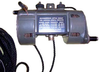
Time Delay Beam Steering
This is pretty much the same as the 1932 General Radio Sound
Ranging patent 1874196 except the GR patent is for sound
and the Fenwick patent is for radio.
The "Beam and null switch step steerable antenna system" U.S.
patent - 4063250
by Richard
C. Fenwick (Electrospace
Systems) is a great explanation of time delay beam
steering. The "phased array" antenna is a special case of
the time delay steered antenna. Note that in the time delay
steered array the direction of the maximum lobe is frequency
independent whereas in the phased array it is a direct function of
frequency. The control box that switches the coax delay
lines also has a null steering switch. So after setting the
direction of the maximum lobe you can try the half dozen or so
null positions to reduce an interfering signal.
Fenwick also patented a "Three band monopole antenna" 4145693
that was sold with the beam steering network by
"Omega-T". This antenna has vertical polarization on
the lower bands where the upper elements act as a capacitive top
hat but on the two highest bands the upper elements act as half
wave dipole antennas with horizontal polarization.
3345635
Folded vertical monopole antenna, Richard
C Fenwick, Roger
A Markley, Collins
Radio Co, 1967-10-03, 343/845; 343/752; 343/899 - distribute
antenna over the surface of a regular solid.
3548310
Antenna current distribution measurement system, Richard
C Fenwick, Collins
Radio Co, 1970-12-15, 343/703 - a rope positioned trolley moves a
tiny loop antenna that's switched on and off causing a VSWR change
on the main antenna
4063250
Beam and null switch step steerable antenna system, Richard
C. Fenwick, Electrospace
Systems Inc, 1977-12-13, 343/844; 333/156; 343/894; 333/101; 342/374 -
4145693
Three band monopole antenna, Richard
C. Fenwick, Electrospace
Systems Inc,1979-03-20, 343/722; 343/745; 343/850; 343/861 -
4290071
Multi-band directional antenna, Richard
C. Fenwick, Electrospace
Systems Inc, 1981-09-15, 343/819; 343/815; 343/833; 343/834 -
LZ1AQ: Active
Wideband Directional Antenna with Vertically Polarized Small
Loop and Small Dipole - Variable
Delay Line Kit for Active Antenna Phased Arrays (model VDL-1)
- Kit
description -
Counterpoise
Wiki
says "used with radio transmitters or receivers when a normal
earth ground cannot be used because of high soil resistance or other reasons".
This comes up when the antenna is not symmetrical. For
example a dipole in free space is symmetrical and so needs no
ground or counterpoise. A DX dipole, i.e. up 1/2
wavelength is close to a free space dipole and needs no
counterpoise. But if a dipole is being used for NVIS operation up 1/4 wavelength and
the dirt (or sand) has poor electrical conductivity then a
counterpoise (reflector) will greatly improve NVIS operation.
If you insert an imaginary ground plane through the
center of the center insulator of a dipole, throw away the left
side and rotate the remaining 1/4 line counterclockwise you end
up with a 1/4 vertical that needs to work against ground, i.e.
an antenna that's unsymmetrical. The e-filed lines should
look the same as before for proper operation. That
requires a reflector at the ground plane.
If the dirt is of poor electrical conductivity, like sand, then
the antenna will not work as you might expect. A
counterpoise is what's added to get the unsymmetrical radiator
to work sort of like it's symmetrical counterpart. There
are a number of ways of doing that. A solid metal sheet
works very will, for example a metal car roof. The metal
does not need to be solid, so a screen where the length of the
holes is say less than 1% of a wavelength would also work
well. For a 40 meter wavelength that would be 0.4 meters
or about a foot.
Another approach is to use a number of 1/4 wavelength
radials. For example AM broadcast stations do that.
To get the electrical length correct some tweaking is needed
because of the properties of the dirt.
Another approach used by pedestrian mobile operators is to drag
a wire. It does not need to be a 1/4 wavelength because of
the capacity of the wire to the dirt, so it's common for the
length to be much shorter. Dragging multiple wires or a
plate may allow an even shorter wire to work well.
Concrete
Concrete typically has either rebar or wire mesh embedded to
minimize cracking. It's pretty easy to make an electrical
connection to either of those, but can be a lot of work to be
sure they are all bonded to each other. Note: You do
NOT want any wire mesh or re-bar to touch dirt. For
example a ground rod under concrete that's connected to rebar is
a very bad idea. That can lead to the metal rusting away
leading to failure of the structure. There is a housing
development built on the mud flats adjacent to the San Francisco
Bay that had that problem.
Pattern
Classically the pattern of an antenna is presented in two
ways. The azimuth pattern is a circular plot of gain at
some specified take off angle. The elevation pattern is a
half circle plot of gain. Both plots are at some specified
frequency. For example see the TCI 651T plots.
Recently (Dec 2016) there's been some discussion about using
drones (quad copters) to make HF antenna pattern
measurements. A number of prior art papers have been
cited:
Beam calibration of radio telescopes with drones, Chang et
al, 2015 (1505.05885v3.pdf)
- a microwave horn fed from a noise source is used on a hexcopter
to send to ground based 5 meter dish antenna. The drone flew
close to the Fraunhofer distance (Wiki,
antenna-theory)
which for a 5 meter dish operating at 1 GHz is 167 meters.
Measurement and Modelling of HF Antenna Gain and Phase
Patterns and the Effect on Array Performance, Jenkins &
Petrie, 1997 (00608612.pdf) - describes the
Xeledop system. Uses airplane with UHF differential GPS
corrections to improve accuracy.
A comparison of modeled and measured HF antenna array
patterns (Xeledop) , Jenkins, 1996 (P502025.pdf)
- an airplane was used to fly a transmit antenna (selectable H
or V polarization) around a ground based antenna and generate
the pattern diagrams. The modeling was done using
NEC2. The modeled result had higher errors ( p to 14%) at
the lowest frequency (5.1 MHz). Ground conditions such as
freezing also have a big impact on the actual pattern.
In order to calculate the far field distance for an HF wire
antenna, like a dipole the three conditions from antenna-theory
should be applied:
1. R>(2D^2)/(WL) - Fraunhofer distance
2. R>>D - size of antenna ( for a dipole it's WL/2
for the antenna so 5*WL overall)
3. R>>WL this says at least 10* WL of 150 meters, or 1500
meters (a little short of a mile) for 2 MHz.
Patents
The US patent
office is full of antenna related patents. I have
found that there are some great ideas that have never made it into
text books, maybe because of the patent protection. My Electronics page Antenna section has a number
of patent links. The US patent office has greatly improved
in the last couple of years and now has ALL patents on line.
Prior to some year (in the 1970s) they are only available as
images so are only accessible by patent number or class.
Google
patents has used Optical Character Recognition (OCR) to scan
all the US and many world and foreign patents so you can search
Google patents for key words, that's something you can not do at
the USPTO web site. But the OCR is far from perfect so the
search strategy needs to take that into account. 2016 update
that's still the case.
AN/VLQ-12
Crew Duke antennas made by First RF (Google
Patents)
Related
An
Instantaneous Direct-reading Radiogoniometer by R. A. Watson
Watt -
Electronics
GRA-71 Coder-Burst
Transmission Group -
Magnetic
Recording
Propagation
Radio Direction Finding
RCS-5 Chirp Sounder
Storm Scope
SkyScan
Links
Review of Conventional Tactical Radio Direction Finding
Systems, Read, 1989 (ADA212747.pdf),
64 pages, mostly theory, but includes WJ-8975A
Pseudo-Doppler and specs for: R&S PA2000, WJ-8975A, R&S
PA555, EM Systems E210, Thomson-CSF TRC296, ESL AN/MRD-501,
WJ-8976.
Radiolocation Technieues, Rose, NATO, 1993, (ADA264667.pdf),
11 pgs includes discussion - "Would you comment on how to make a
cove"t vertical Incidence sounder? Actually, there Are two
methods. First, it Is easy to modify the frequency synthesilyer
to follow a peeudo.random hopping sequence instead of a linear
sweep, the sounder hops until the ionogram is constructed. We
have tried this and it works. Second, we are testing 40 kHz
spread.-spectrum signals which are undetectable. There is no
reason this couldn't be swept in frequency to measure
Ionospheric height.
Spatial Properties of Ionospheric Radio Propagation as
Determined with Half-Degree Azimuthal Resolution, Sweeney,
1970, 98 pags (AD0709069.pdf)
-
Electronic Warfare and Signals Intelligence, South China Sea
Military Capability Series, 2020 (AD1128255.pdf)
35 color pages -
Command, Control, Communications and Intelligence (C3I)
Project Book, 1993 (ADA262464.pdf),
233 pages - lists nomenclature of many systems
Techniques for Locating a Remote HF Transmitter from
Single-Site Measurements, Reilly, 1983 (ADA132014.pdf)
27 pgs - theory & equations
A Practical Guide to the Design and Construction of a Single
Wire Beverage Antenna, Spong, 1980 (ADA095852.pdf)
- theory and practice for 3 & 13 MHz
Antenna Catalog, Vol IV, Unclassified Aircraft antennas, Oct
1960, 325 pgs (AD0323192.pdf)
Shortened Antennas for
Portables by Dennis Starks
Army Mars
- antenna page
Antennas
- active loops and whips by Charles Wenzel
Back to Brooke's Products
for
Sale, Military Information,
Home
Page created 1 Nov 2001.


