LST-5 Series UHF Radios
© Brooke Clarke 2010 - 2023
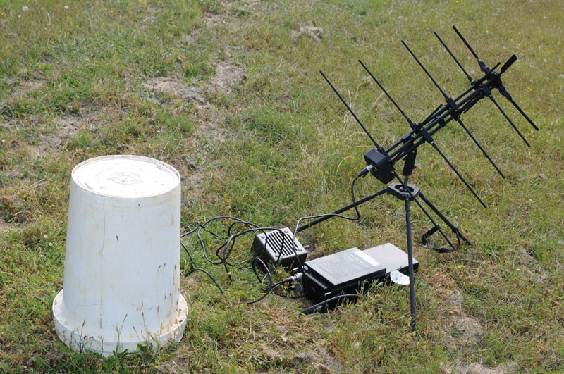
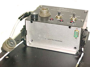
Fig 0
LST-5B radio w/ D&M C152-1-1 SATCOM Antenna & LS-454 (modified) Speaker in
Field
|
|
|
X-Mode Con:
MS3114E16-26S
|
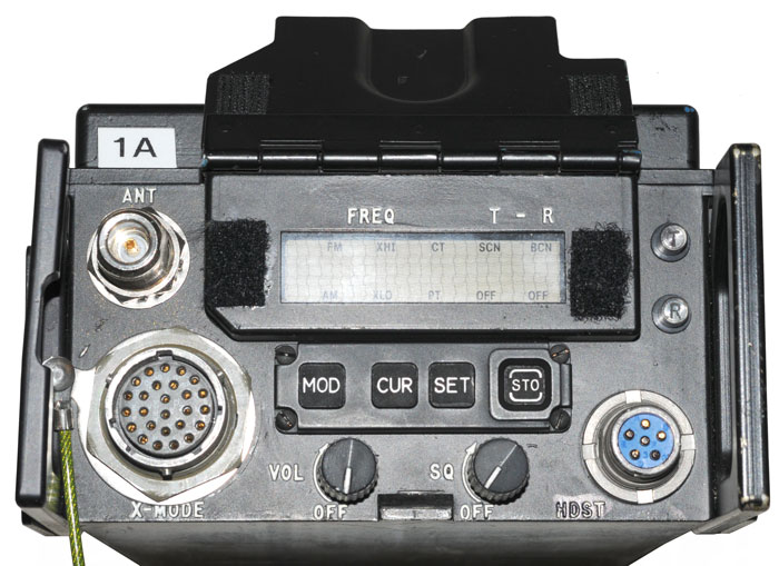
Fig 2
Front, Left (Label) & Top
|
|
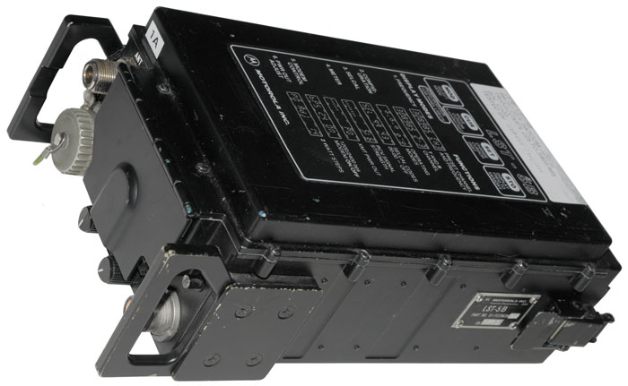
Fig 3
Rear, Left (MWO) and Top
|
|
Background
The LST-5 series was developed by
Motorola starting in 1984. They operate in the military UHF
band between 225 and 400 MHz. This is the band used my
military aircraft and satellites. Motorola made the LST-5A,
LST-5B, LST-5C, LST-5D and LST-5E (aka AN/PSC-10()) . The
first DAMA (
Wiki)
contract was to Magnavox (later Hughes then Raytheon) in 1994 as
the PSC-5. In Nov 1995 Motorola started selling it's LST-5D
units. In year 2000 Motorola developed a Remote Control Unit
(RCU) to allow the radio operator to be in a location where there
is not satellite visibility. ( A radio operator on a
mountain top anywhere near an enemy is called a target).
The radio supports AM (2 or 5 W), FM (4 to 20 W), Voice and data
(MIL-STD-188C) using 1200 bps BPSK and DBPSK modulation as well as
2400 bps shaped BPSK modulation.
The DAMA system is being phased out. The problem is that
someone with a higher priority (say a general ordering coffee)
will bump communications with a lower priority (say a special ops
team). The replacement will be a system using MELP vocoding
(
Wiki)
and digital data transmission.
This radio supports use for satellite communications or
terrestrial Line Of Sight (LOS) communications. A military
UHF LOS only radio typically only has an output power of a few
watts whereas this radio has up to 20 Watts of output power.
Note to achieve the high power either an AC supply or a
rechargeable battery must be used. The
BA-5590/U primary battery is limited to
2.25 Amps by an internal fuse and trying to use it for high power
operation will blow the fuse in the battery (or maybe the fuse
that's inside the LST-5B?
Auxiliary Equipment
AN/CSZ-1 Sunburst Cryptographic
Processor
ANDVT -
KY-99 Advanced
Narrow-band Digital Voice Terminal (ANDVT)
KY-57/KY-58 -
KY-57 Transmission
Security Device
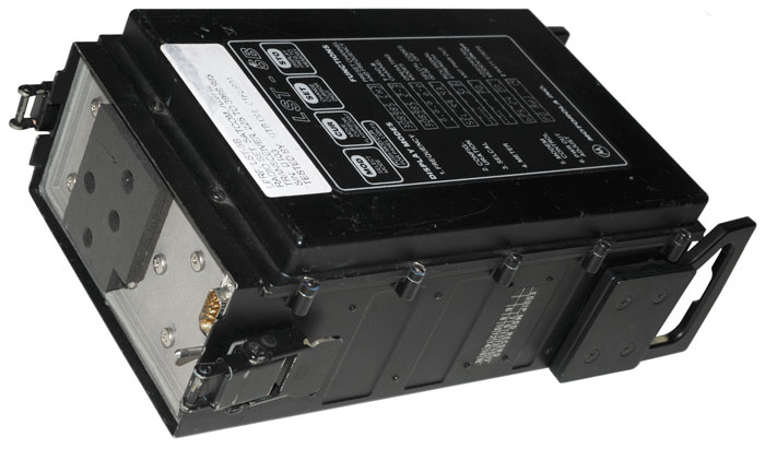
AM-7175/URC - 200 Watt RF amp (PTPA-200A)
PTPC-100 Control &
PTPE-100/PTPE-101
225 - 270 MHz 13 dB gain low noise Preamplifier
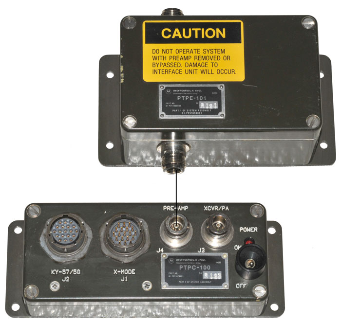
|
PTPE-101 Connectors:
J1 Control: Type-Nf
J2 Antenna: Type-Nf
PTPC-100 Control Connectors:
J1 X-Mode: MS3114E14-19P
J2 KY-57/58: MS3114E14-19S
J3 XCVR/PA: Type-Nf
J4 Pre-Amp: Type-Nf
LST-5 X-Mode Con:
MS3114E16-26S
KY-57 Radio Cable Conn:
MS3126E14-19S
LST-5 to PTPC-100 cable connectors:
PTPC-100 end:
LST-5 end:
KY-57 to PTPC-100 cable connectors:
PTPC-100 end:
KY-57 end:
|
|
|
DMDG - Digital Message Device Group - Special Forces Burst
Communications System
AN/PSC-3 man-pack satellite radio & AN/VSC-7 vehicle Radio
KG-34 Shipboard/Fixed Plant: Key Generator, Electronic
Full-Duplex, Jun 1971 - voice system used with separate vocoder.
KG-84 NSA Digital Data Security device (
Wiki)
UYA-7 Digital Data Group
UGC-129 Teletypewriter Set
PC computer using special X-mode cable.
LSSC-100 Communications Terminal
Part # 01-P32561A001 - holds the LST-5 and a
KY-57
and has a small control panel.
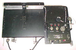
|
overall top view
|
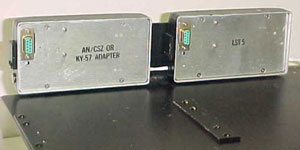
|
AN/CSZ or KY-57 on left
LST-5 on right
|
|
Battery box or Power
Supply behind control panel
|
Retransmission can by done by connecting two radios using a
special AUDIO cable p/n 30-P27587D001, It's a "Y" cable
with provision for a handset.
For crypto retransmission a special cable with four X-mode
connectors is required. (it will be expensive, bulky and heavy).
Accessories
LSAD-100 11-32 VDC or 120/240 VAC
Power Supply
PTA-200 115/230 VAC Power Supply
HYP-5 15-30 VDC Power Adapter
PDFA-101 Mil Vehicle power adapter with VIC-1 type DC input and DC
output 4 terminal connectors, like on
MT-1029
Remote Control Unit (RCU)
Vehicle & Aircraft mount
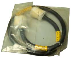
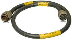
Data & Control Cables
PTKY-104, 30-P27585D002, 94990 Cable
KY-57 or CSZ-1 to LST-5, LST-5A, LST-5B X-Mode
Fig 1.
|
Fig 2
 |
KY-57
RADio
|
KY-57
Function
|
LST-5
X-mode
|
A
|
Rx
CT in |
|
B
|
|
|
C
|
PT
in |
|
D
|
|
P
|
E
|
Rx
Data out |
nc
|
F
|
|
nc
|
G
|
Gnd |
A, shell
|
H
|
Gnd |
A, shell |
J
|
|
|
K
|
|
|
L
|
PT
or ? |
D
|
M
|
PT
out |
C
|
N
|
Tx
Data in |
R
|
P
|
|
nc
|
R
|
DCD |
A, shell?
|
S
|
PTT |
shell?
|
T
|
Tx
Clk |
L
|
U
|
Tx
CT out |
B
|
V
|
|
nc
|
Spare parts & Module kit
Training Programs & Equipment
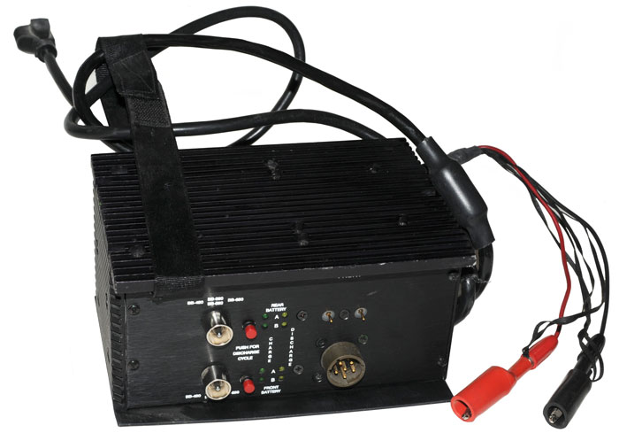
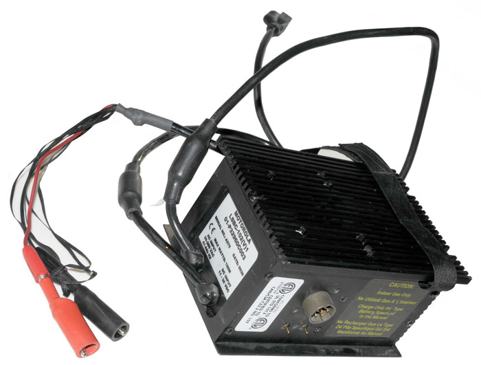
LSBC-102 Battery Charger
|
|
|
The input can be either:
95 - 260 VAC @ 47 - 440 Hz
or
11 - 36 VDC
|
|
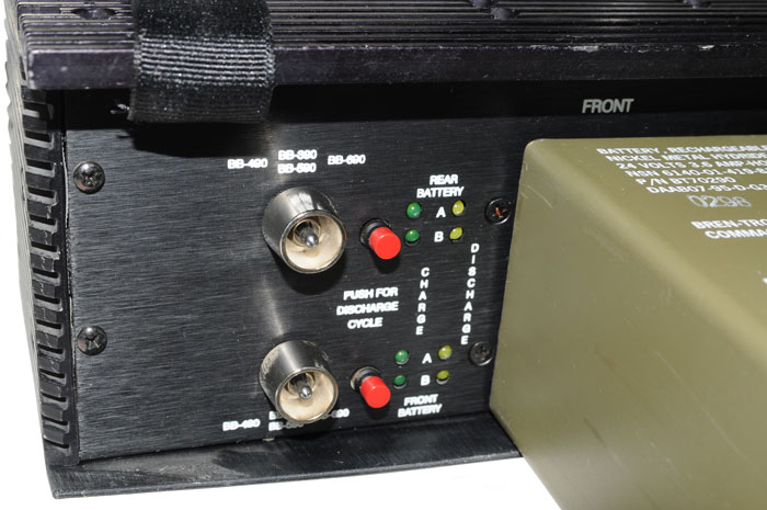
Toggle Switch:
BB-490
or
BB-390/BB590
or
BB-690
Red Push-button:
Push for Discharge Cycle
LED for the A and B sides
Green for charge
Yellow for discharge
|
KeCo
Switch
allows easy switching between LOS and Satcom antennas.
6975178
Military communications antenna switching, Donald
J. Kessler, David
N. Coates, Dec 13, 2005, 333/105, 455/78, 343/906, 333/262, 455/90.1 -
|
|
Antennas
Line Of Sight (LOS)
These are the dildo type antennas like used on the
RT-1319 (PRC-113).
Satellite
These are the circular polarization tripod mounted like the Dorne
& Margolin.
Antenna
|
Gain
dB
|
D&M
C125-1
|
5
|
D&M
C120
|
6
|
D&M
C121-1
|
10
|
D&M
C122-2
|
12
|
D&M C152-1-1
|
?
|
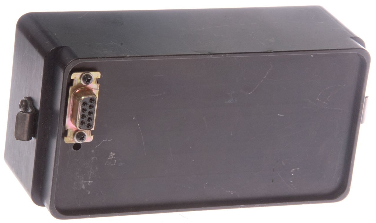
Power Supplies
The radio has a DB-9m connector on
the rear (bottom) face (
Fig 2) that interfaces
with the power supply.
Pin
|
Function
|
1 &
6
|
On/Off
sw
|
3
|
+24 to
radio
|
5
|
Ground
|
2, 4,
7, 8, 9
|
n.c.
|
Note: the Radio On/Off switch is brought out as two isolated
contacts at pins 1 & 6 so that a relay can be used to turn the
power supply on and off. This is very handy when an AC power
supply is being used.
PTL-200 Battery Pack
The battery pack holds any of the
BA-5590 family of batteries (or
my
5590BA battery adapter)
although the LST-5A and LST-5B only had the BB-590 or BA-5590
available at that time.
Note: Exceeding 10 Watts
output power may blow the fuse in a BA-5590/U battery.
Use a rechargeable battery (BB-590, BB-390, BB-2590, etc.) for
power levels above 10 Watts.
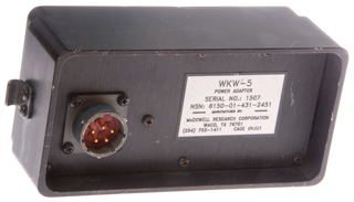
WKW-5
This is a battery eliminator with the DB-9 connector on the
radio side and a MS3470W14-5P for the DC input.
The input is 28 VDC and Vout to be 24 VDC, not sure why the
difference.
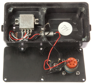
The input goes through a full wave bridge, so the input
polarity does not matter.
Then a EMP filter.
Then a relay that is controlled by the radio in typical
fashion for the LST-5 type radios.
Input connector Panel:MS3470W14-5P, Cable: ___TBD___
MS3470W14-5P
Pin
|
Function
|
DB-9
|
wire
|
Function
|
Relay
|
A
|
DC
|
1
|
Red
|
+28
|
A2 & B2
|
B
|
DC
|
5 & 6
|
Blk
|
-28 Gnd
|
Coil
|
C
|
nc
|
9
|
Wht
|
|
Coil
|
D
|
nc
|
3
|
Wht
|
|
A1 & B1 |
E
|
nc
|
7
|
Wht
|
|
A1 & B1 |
MS3470W14-5P
|
DB-9f pin1 lower right, pin5 top right
pin 6 upper left, pin 9 lower left

|
Inside
|
Memory Battery
There is an LTC-7PN 3.5 V battery
soldered on the CPU board that maintains the preset data.
It's supposed to be replaced once every 2 years.
This radio has a paper sticker with a date of 01FEB01 and today
is 04JUN2010 so the battery is over 9 years old and still
working.
Versions
LST-5A
For s/n in the range below F178
there is a 7th mode for real time clock &
Calander.
No modem. Maybe OD in color.
LST-5B
Adds an internal modem.
LST-5C
When the
BA-5590
Lithium battery is used the "C" radio will develop full output
power. This means that the radio draws less than 2.25 Amps
at 20 volts. This requires a more efficient RF power
amplifier than the one used in the "A" and "B" versions.
Front panel fuse above and to the right of the handset
connector, instead of an internal fuse.
LST-5D
Adds Demand Assign Multiple Access
(DAMA) which reassignes the satellites bandwidth based on the
priority of the calls that are active. This is similar to
the system used on the autovon telephone network. For
example see the
TA-1042 info on
Flash Override, etc.
LST-5E
Adds embedded encryption (CSZ-1A
Sunburst II). The "B" or "C" models can be upgraded to
"E".
Modifications
The MWO sticker has had 1, 2, 3, 4
& 5 Blacked out leaving 6 to 18 showing.
If you know what these mods were please
let
me
know.
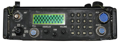
Operation
See the Front Panel photo (
Fig 1).
When the MODE button is pressed the display cycles through the six
main menu pages. A mode chart is printed on the top (
Fig 3) of the radio.
The CUR button moves the cursor horizontally to each of the fields
that can be changed.
The SET button increments the field.
The STO button saves the change to memory.
|
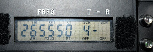
1. Frequency
The 4 - <blank>
should be
4 - 1 (spluit freq chan)
the cursor was on the 1
and the camera shutter
opened with the blink was
blank.
When both the 4 and the 1
are blinking, pressing SET
causes the display to show
CH1. When SET is now
pressed you can see the channels.
CH1: 265550
CH4: 297850
delta: 2.3 MHz
|
|
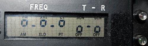
2. Configuration
These are like toggle switches, shown:
FM (or AM)
XHI (or Tx pwr low)
CT (or plain text)
SCN:OFF (or scan on)
BCN:OFF (or beacon on)
|
|
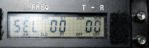
3. SELCAL
the Tx code (center of display) is 00
the Rx code (at the right) is also 00
|
|
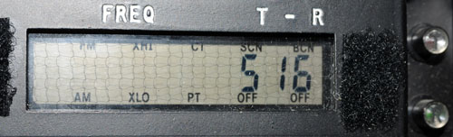
4. Meter
showing SI 6 (Rx Sig str) & no bars
when transmitting it will show:
PO and bars (2 Watts per bar)
|
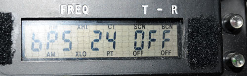
|
5. Modem Control
showing 24 (or 12)
showing OFF (or on)
|
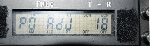
|
6. Power Out
|
Related
RT-1319
VHF-Hi & UHF Aircraft tranceiver
VRC-83 part of the
GRC-206 FAC system
PSC-5 Portable SATCOM terminal
RT-1672 Multi-band Multi-mission
communication terminal - supports voice and data modes both PT
& CT
Wanted male & female versions of this connector to
make extender card or extender cable. Contact Brooke
80 terminal connector 0.075" pitch
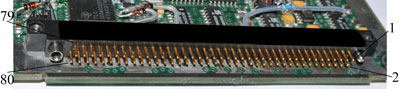
RT-1672 Motherboard top
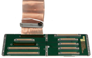
|
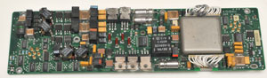
RT-1672 Power Supply PCB
top
|
RT-1672 Motherboard bottom
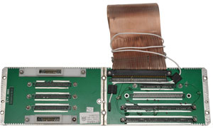
|
RT-1672 Power Supply PCB
bottom
|
TM 11-5820-1130-12&P
|
|
RADIO
SET
AN/PSC-5 (NSN 5820-01-366-412 (EIC: N/A) {TO 31R2-2PSC5-1;
NAVELEX EE125-WU-OMI-010/PSC-5; TM 10191A-12&P/1}
TM 11-5820-1130-30&P1 |
RADIO
SET
AN/PSC-5 (NSN 5820-01-366-412 (EIC: N/A) {TO 31R2-2PSC5-2;
NAVELEX EE125-WU-MMO-010/PSC-5; TM 10191A-30&P/2}
(THIS ITEM IS INCLUDED ON EM 0169)
TM 11-5820-1131-12 |
Links
page
page created 2 Jun 2009.