MT-1029 Radio Mount

© Brooke Clarke, N6GCE
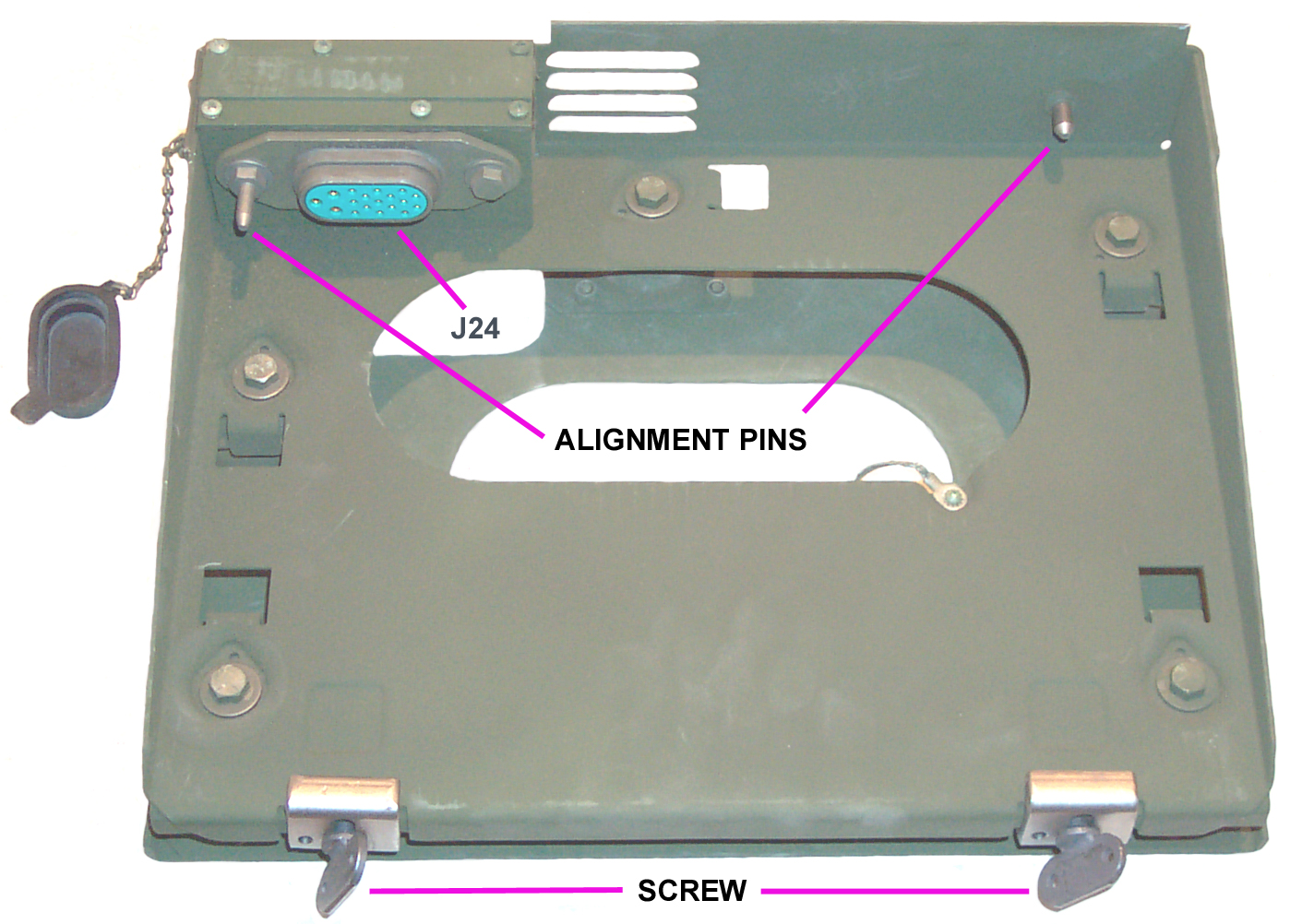

MT-1029 Top
MT-1029 Bottom
MT-1029
                  Jumpers in Box
Mtg Hdw Bag


Background 
Install Kits 
VRC-12 Cables 
    DC Power 
    CX-4720
    CX-4721
    Antenna Cables
    CX-4722 Ant Control
    CG-1773 BNC Coax Antenna
    Control & Audio
    CX-4723
VINSON Voice Encryption with Mounts 
Test Equipment 
Documents
    VRC-12 Manuals    
    VRC-53 & VRC-64, GRC-125 & GRC-160 Manuals 
    PS Magazine Articles 
Sources  
Links 

Background

When electronic equipment is mounted in a vehicle there needs to be some protection from shocks.  This is accomplished with a "Mount".  These are typically made up of a base plate that attaches to the vehicle and an equipment tray that attaches to the base plate with shock absorbers.  The equipment tray holds the radio or other equipment such as COMSEC gear.  Some mounts are purely mechanical while others, like the MT-1029 also contain electrical circuitry.

The PRC-8, PRC-9 and PRC-10 radios where used in Vehicular installations by means of the AM-598 Audio Amplifier/Power Supply.  But the AM-598 had shock mounts on the bottom and a Vehicle DC Power 4 socket connector on it's front panel.  So it looks like the MT-1029 mount with DC and control wiring was introduced with the AM-2060, RT-246 & RT-524.

To just shock mount a PRC-25, PRC-77 or other equipment in the same form factor the MT-3823 can be used.  It does not have the electrical connections like the MT-1029.

MT-1029 Description

The MT-1029 was designed to hold one the following items:
The first two radios above and the one radio below are the radios used to make up what's called the VRC-12 Series of Vehicular Radio sets. 

In most cases the MT-1029 is not directly bolted to the vehicle, instead a metal mounting plate is attached to the vehicle, maybe with some brackets and the MT-1029 is bolted to the plate.  Sheet metal alone could not hold all the weight of a radio setup without the extensive reinforcing supplied by the mounting plate that's part of the install kit.  Note that the mounting plate might hole only a single MT-1029, an MT-1029 plus an MT-1898, two MT-1029s, or two MT-1029s and two MT-1898.  These are just possibilities for non COMSEC systems.  COMSEC systems would have in addition one or two KY-57s in mounts.

MT-1898 Description

The MT-1898 was designed to hold the R-442 Receiver. Manual frequency control, but does it accept remote channel control using VIC-1?

Electrical Description

Both mounts have the same electrical configuration.  There are 4 electrical connectors.  They handle power and control signals to/from the radio and are designed to allow adding more equipment by daisy chaining, greatly simplifying radio installations.
J21 Main Power Receptacle is the DC power input from the vehicle battery
This panel receptacle is an MW20-M-MA00. Has Male Pins.
J22 Power/Audio/Control Receptacle is the interface for Vehicle Inter Communication (VIC) system or COMSEC J-Box.
J23 Power Transfer Receptacle is the DC power output.
This panel receptcale is an MW20F(M)A00. Has Female sockets.
J24 is the interface connector that mates directly with the radio or AM-2060.

There is also a junction box that contains an electrical link.  This link can be set in two different ways in the D.C. power path.
The E24 terminal is always connected directly to the vehicle 24 volt battery.
The E22 terminal is connected to J22 going to either VIC-1 or COMSEC to switch the radio on or off remotely.
The E23 wire terminal powers the radio.  When it is attached to the E24 battery terminal the radio power is controlled only by the radio.  When it's attached to the E22 terminal the radio power is controlled by the VIC-1 or COMSEC equipment.
It's unfortunate that the TMs use the term "+25.5 VDC Common" not to mean the ground return for the power supply, but instead to mean a positive switched power buss. This switched DC appears on pin "C" of all four connectors.  Pin "B" of all four connectors is the Battery hot terminal.  Grounds appear on all for connectors at pin "A".

Install Kits

Install kit Mk numbers for VRC-12 Series (from TM 11-5820-401-10-1HR) & AM-2060:


VRC-12
VRC-43
VRC-44 VRC-45 VRC-46 VRC-47 VRC-48 VRC-49 VRC-53
GRC-125
VRC-64
GRC-160
RT-246
1
1
1
2
0
0
0
0
-
-
RT-524
0
0
0
0
1
1
1
2
-
-
R-442
1
0
2
0
0
1
2
0
-
-
PRC-25
-
-
-
-
-
-
-
-
1
0
PRC-77
-
-
-
-
-
-
-
-
0
1
M151 MUTT Jeep
Mk-1221
Mk-2147
SC-D-691342

Mk-1220
Mk-1241
-
Mk-1234
Mk-2147
SC-D-691342
Mk-1306
Mk-2147
SC-D-691342

Mk-1442
Mk-1230
Mk-2147
Mk-2153
Mk-1234

n.a.
Mk-1234
Mk-2149
Mk-1842
M715 PU Truck
Mk-1239
Mk-1222
-
-
Mk-1243
Mk-1226
-
Mk-1227
Mk-1243 Mk-1243
M561 Gamma goat
Mk-1245
-
-
-
Mk-1252 Cab
Mk-1246 Trlr
Mk-1245 Cab
Mk-1253 Trlr
-
Mk-1254 Mk1252c
Mk1255cv
Mk1246t
Mk1255tv 
Mk1252c
Mk1255cv
Mk1246t
Mk1255tv
M34, M35, M135, M211
2.5T Truck
Mk-1242
-
-
-
Mk-1244
Mk-1223
-
-
Mk1244c
Mk1240t
Mk1244c
Mk1240t
M37() 3/4T PU Truck
Mk-1247
Mk-1231
-
-
Mk-1232
Mk-1247
-
Mk-1230
Mk-1232
Mk-1232
M51 5T D Truck
-
-
-
-
Mk-1738
-
-
-
Mk-1738
Mk-1738
M342 2.5T D Truck
-
-
-
-
Mk-1738 -
-
-
Mk-1738 Mk-1738
General Purpose Kits
Mk-1439 Mk-1231 Mk-1440 Mk-1444 Mk-1443 Mk-1445
Mk-1442 Mk-1438 Mk-1454
Mk-1454
HMMWV M998, etc.
?
?
?
?
?
?
?
?
?
?

Mk-1842, Mk-2147 & Mk-2149 are the install kits for a PRC-77 with a KY-57.= in an M151 MUTT.

The Tracked and Water vehicles do not have kits like the wheeled vehicles.  They are configured part by part, some of which are custom drawing numbers.  Covered in TM 11-5820-401-10-2HR

These are all VHF low band radios and typically were used with the AS-1729 Antenna.  The distance from the radio to the antenna varies with vehicles and so the CX-4722 MX-6707 band control cable and the CG-1773 antenna RF coax cable will be different lengths in different vehicles.

Maybe the HMMWV was only fitted with the SINCGARS radios and not the VRC-12 or VRC-53 to GRC-160 family?

VRC-12 Cables

Military Vehicles use a standardized cable for supplying 24 Volt vehicle power to onboard equipment.  It consists of a 4 pin connector with a central anchor screw driven by a folding flap to allow connection and removal without tools.  It's completely different from the common MS series circular connectors, thus avoiding confusion.

DC Power

The MW series are very common vehicle DC power connectors.
From Vehicle Battery
MW10F(M)Axx DC Power Connector

MW10F(M)Axx


Input to Equipment
MW20(M)A00
                DC Power Connector
MW20M(M)A00
Output from Equipment
MW20F(M)A00
                DC Power Connector
MW20F(M)A00
Panel connectors have fixed male threaded posts

DC Power Cable Note

The CO-04MOF cable is rated for 21 Amps max. according to a cable supplier.  I don't know if this is exceeded on some duty cycle basis like the ratings for a transmitter where it's on for 1 minute and then off for 9 minutes.  What's the largest load you know of in Amps fed by a CX-4720 or CX-4723?

The RT-246 and RT-524 pull 10 Amps on high power transmit, so a retransmission setup, where only one radio is transmitting (the other will be receiving) will draw maybe 12 amps, not even 20 Amps.

Also the life of the early cables is very long while still in the government packaging, but after exposure to air and temperature cycling it's 8 to 10 years.  If the cable feels tacky or spongy it needs to be replaced.

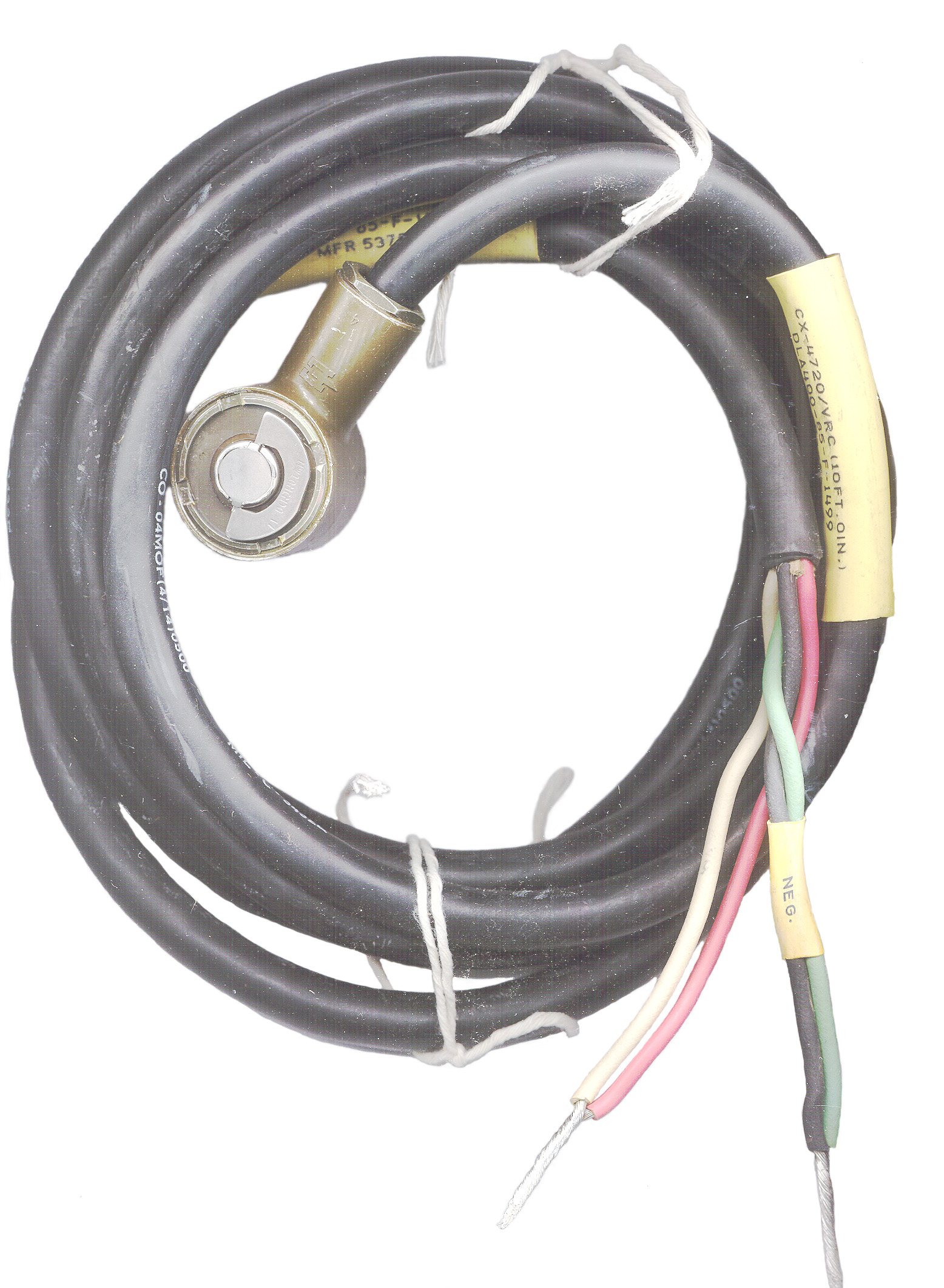
CX-4720 Wire Ends (Battery) to Radio Power Cable

CX04720


 Has a 4 socket connector on one end and wires on the other end.  Typically used to connect from a 24 Volt battery to a radio Mount.  The cable: 4 each # 14 stranded wires. 
Pin
Wire
Function
A
Black & Green Negative
B
Red & White Positive
C


D

maybe gnd for On

CO-04MOF(4/14)0500 MIL-C-3432E.
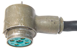
The Connector: MW10M(M)D 17, MIL-C-55181,  M55181/7-03,  55181-1249-85, 20 mV drop at 35 Amps for 4 contacts.  This current rating is for the connector, not the cable assembly.

CX-4721 Radio Mount to Radio Mount Power Jumper Cable

CX-4721


This is a four conductor extension cable typically used to daisy chain Radio Mounts.
The female connector is the same as on the CX-4720.

The four pin Male connector: MW10M(M)A17,  M55181/3-03
CX-4721 Cable
                    Connectors
Note both connectors have female center threaded holes.

Antenna Cables

CX-4722 MX-2977 or MX-6707 Antenna Base Frequency Control Cable

CX-4722


This is a 12 contact cable that connects between an antenna base and either a radio or the AM-2060() for the purpose of controlling the operationg frequency band of the antenna base.
Right Angle connector: U-393/U 12 Pin Plug.  Note in bag:
Type U-393/U connector (Item 2) of the cable assembly has been polarized at 180 degrees.  The user may change this keyway and cable relationship by loosening the three connector flange 1/16" Allen screws and rotating the housing to the desired angle.  After repositioning, tighten screws securely.
Cable: MIL-C-3432E, CO-12LOF(12/22)0350 12 conductors of 22 AWG. Straight connector: U-290/U, 12 socket Plug.

Different cable, for R-1518/URR-71 is marked:
CX4722A/VRC (6Ft, 0 In)
DLA400-79-F-5228
Mfr 55923

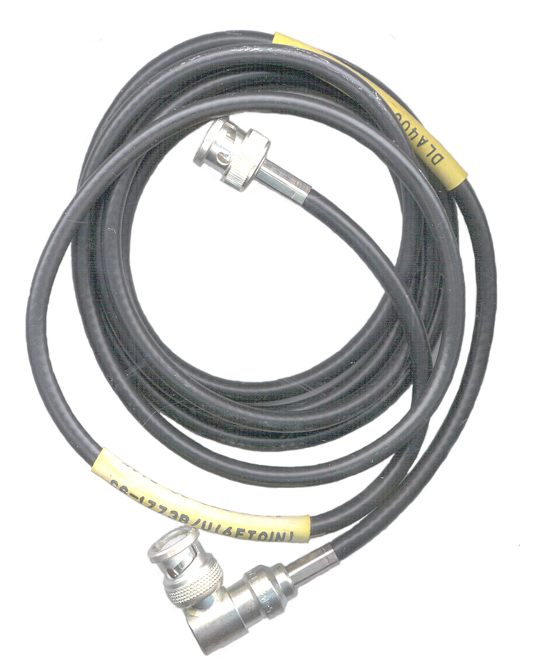
CG-1773 BNC Coax Antenna Cable

CG-1773


Like the CX-4722 this cable comes in different lengths. The suffix letter is the key to the length.  This is a "B" suffix and is 6 feet 0 inches long.

Control & Audio

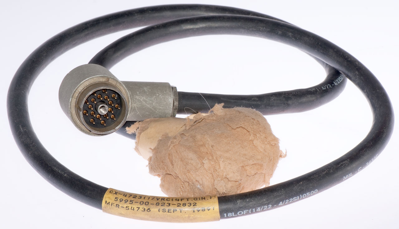
CX-4723 Power, Control & Audio Interconnect Cable

CX-4723 VIC-1
                    Control & Audio Cable
This is the cable that's used between the VIC-1 Intercom system AM-1780 Amplifier and the remote control boxes.

It's very similar to the SINCGARS CX-13292 but they are wired differently.

VINSON Voice Encryption with Mounts MT-1029 or MT-1898

When the KY-57 is used in a VRC-12 Series installation special Junction Boxes are inserted between the Base mounting and the Tray of the MT-1029 or MT-1898.  These junction boxes contain a number of relays and a low power audio amplifier. They are designed to meet TEMPEST requirements.  A KY-57 is needed for each radio so for example a VRC-12 system needs two KY-57s and a VRC-48 needs three KY-57s.
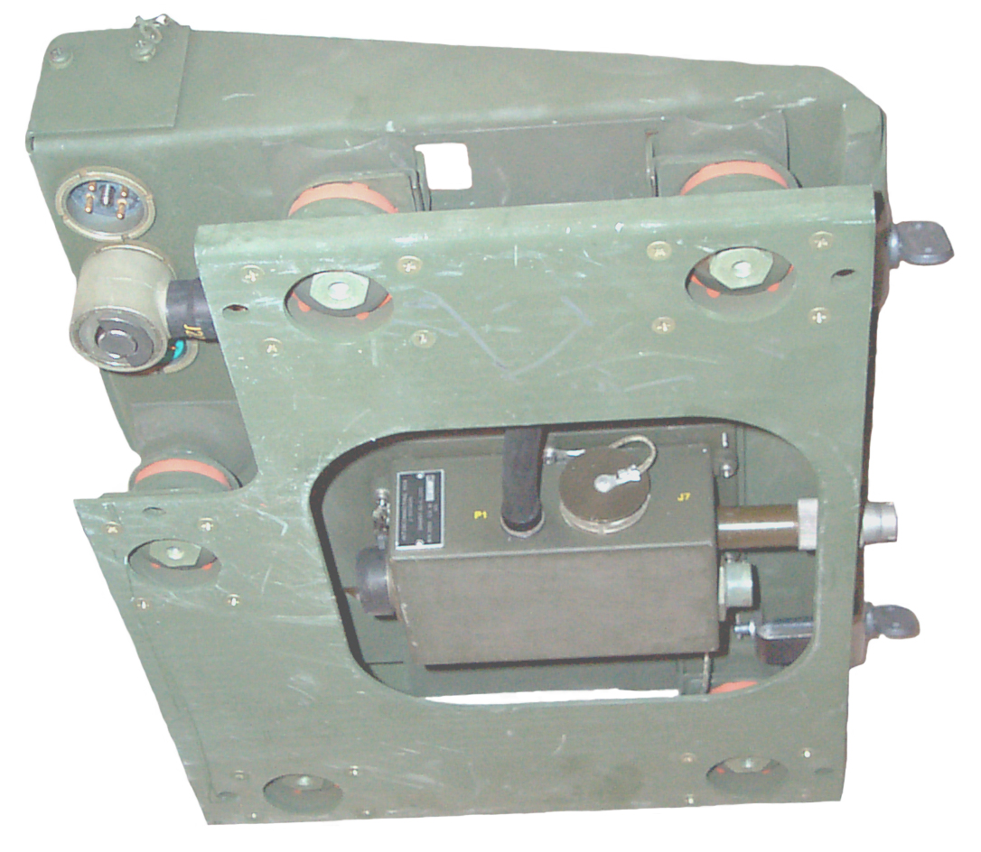
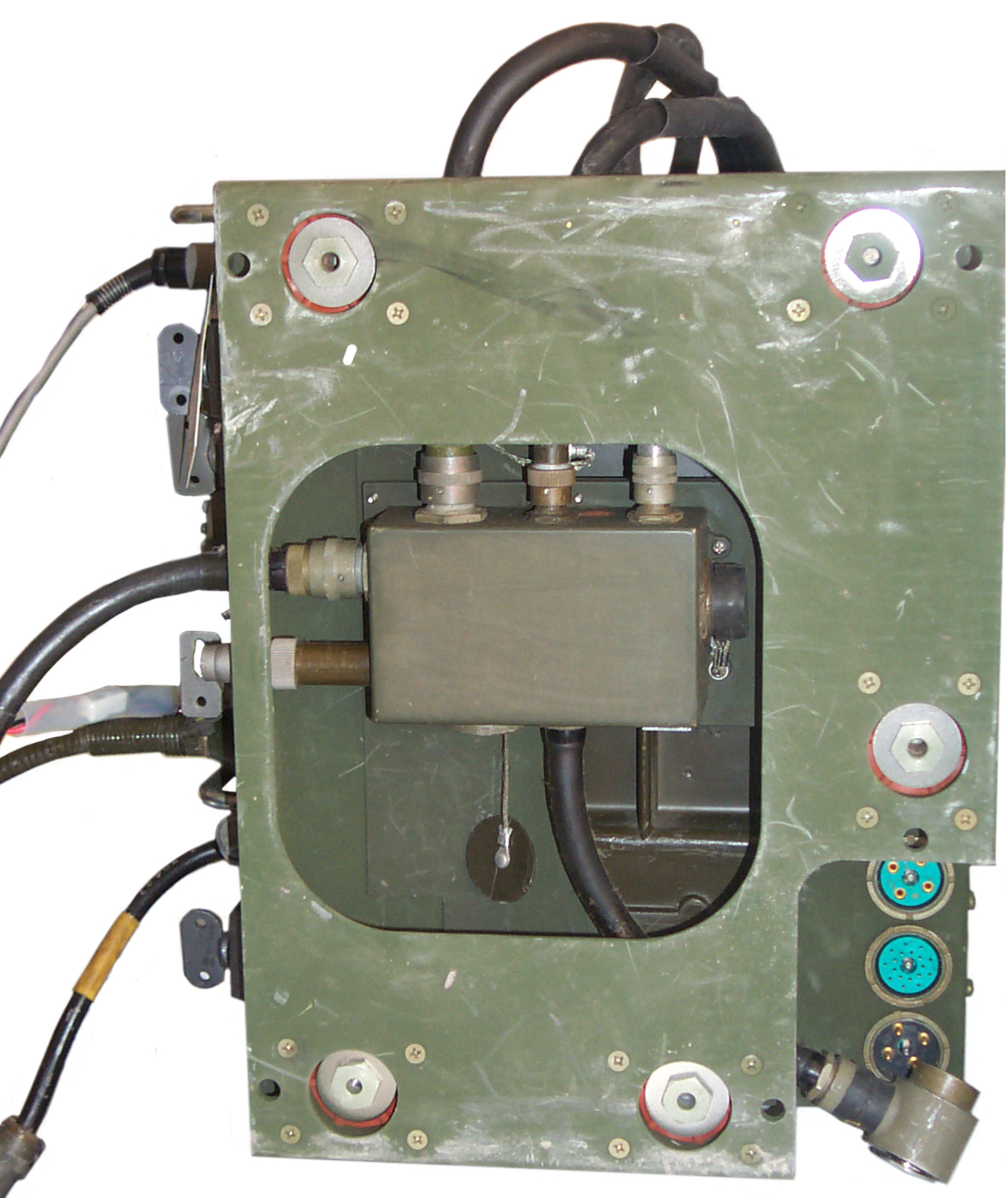
J-3513 Box

Is installed with the box pointing down (labels read correctly)  inside the MT-1029 with the extended AUDIO connector pointing to the front.

Installing the J-3513 into the MT-1029


J-3513
                    in MT-1029 MT-1029 bottom
                    View J-3513 & cables

  1. Use a 1/2" wrench to remove the 5 each 5/16-24x1" bolts from the top of the equipment tray.
  2. Either disconnect the ground strap from the equipment tray, or when installing the J-3513 do not trap it.
  3. Remove the SC-C-930707 Clamping Plate from the J-3513 by unscrewing 4 each #2 Flat Head Philips screws and set aside.
  4. Install the J-3513 between the equipment tray and the base of the MT-1029 with the extended  AUDIO connector (J5) pointing to the front and the box portion pointing down (labels are right side up).  Be sure the sheet metal tabs go into the notches and all the parts are seated properly.
  5. Re-install the SC-C-930707 Clamping Plate being careful to properly position so it clamps the equipment tray.
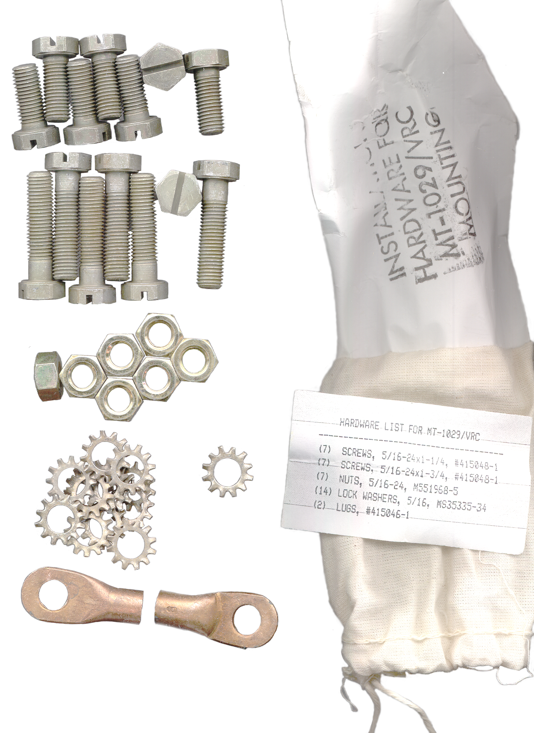
  6. Use 5 each 5/16-24x1 1/4" bolts from the MT-1029 Install Hardware bag and the flat washers that were under the original bolts to install attach the equipment tray back to the MT-1029 base.  Do NOT use the lock washers in the Install Hardware bag, doing so will result in the bolt heads protruding above the plane of the equipment tray.  Instead put a drop of Loctite 222MS on the bolt.
  7. After tightening the bolt check with a straight edge to be sure the bolt head is below the equipment tray surface and will not rub on the radio.
  8. If you disconnected the ground strap in step 2, reconnect it now.
  9. Plug the connector on the cable coming form P1 on the J-Box into J22 on the MT-1029 and tighten the wing handle until it's snug and the long axis is aligned with a pair of the notches so that when it's folded flat it will engage the notches.

J-3514 Box

Is installed with the box pointing down (labels read correctly)  inside the MT-1898 with the extended AUDIO connector pointing to the front.

VINSON Cables

For more on the VRC-12 & PRC-77 VINSON cables and Junction Boxes see the USM-481 VINSON Interconnect Tester web page.

SC-D-691342

The large support assembly or Hutch surrounds the PRC-77, RT-246 or RT-524 and it's top surface provides a place to mount one or two KY-57 boxes in MT-____   mounts.

Test Equipment

PRM-34 - Frequency, Fwd. Power, Rev Power, and Sensivity
USM-481 - VINSON Interconnect Box and Cable Tester for VRC-12 Series & PRC-77

Documents

VRC-12 Manuals

TM 11-5820-401-10-1HR  Wheeled Vehicles & General Purpose
Radio Sets
AN/VRC-12 (NSN 5820-00-223-7412),
AN/VRC-43 (5820-00-223-7415),
AN/VRC-44 (5820-00-223-7417),
AN/VRC-45 (5820-00-223-7418),
AN/VRC-46 (5820-00-223-7433),
AN/VRC-47 (5820-00-223-7434),
AN/VRC-48 (5820-00-223-7435), and
AN/VRC-49 (5820-00-223-7437) (Used Without Intercom Systems)
TM 11-5820-401-10-2HR Tracked & Water Vehicles
Radio Sets,
AN/VRC-12 (NSN 5820-00-223-7412),
AN/VRC-43 (5820-00-223-7415),
AN/VRC-44 (5820-00-223-7417),
AN/VRC-45 (5820-00-223-7418),
AN/VRC-46 (5820-00-223-7433),
AN/VRC-47 (5820-00-223-7434),
AN/VRC-48 (5820-00-223-7435), and
AN/VRC-49 (5820-00-223-7437) (Used With Intercom System)
TM 11-5820-401-10-4
Receiver-Transmitter,
RT-246( )/VRC (NSN 5820-00-892-0623) and
RT-524( )/VRC (5820-00-892-0622)
TM 11-5820-401-20-1
TM 11-5820-401-20-2
Radio Sets,
AN/VRC-12 (NSN 5820-00-223-7412) (EIC: GCC)
AN/VRC-43 (5820-00-223-7415) (EIC: GCD)
AN/VRC-44 (5820-00-223-7417) (EIC: GCE)
AN/VRC-45 (5820-00-223-7418) (EIC: GCF)
AN/VRC-46 (5820-00-223-7433) (EIC
AN/VRC-47 (5820-00-223-7434) (EIC: GCH)
AN/VRC-48 (5820-00-223-
AN/VRC-49 (5820-00-223-7437) (EIC: GCK) (Used With Intercom Set AN/VIC-1(V)) {EE150-JA-MMO-02D/E154 VRC 12, 43}
TM 11-5820-401-34-2-1
TM 11-5820-401-34-2-2
Radio Sets
AN/VRC-12 (NSN 5820-00-223-7412),
AN/VRC-43 (5820-00-223-7415),
AN/VRC-44 (5820-00-223-7417),
AN/VRC-45 (5820-00-223-7418),
AN/VRC-46 (5820-00-223-7433),
AN/VRC-47 (5820-00-223-7434),
AN/VRC-48 (5820-00-223-7435),
AN/VRC-49 (5820-00-223-7437);
Receiver-Transmitters Radio,
RT-246/VRC, RT-246A/VRC (5820-00-892-0623),
RT-524/VRC, RT-524A/VRC (5820-00-892-0622) {NAVELEX 0967-LP-432-3030}
TM 11-5820-401-34P-2-1
TM 11-5820-401-34P-2-2
Receiver-Transmitter, Radio, RT-524/VRC and RT-524A/VRC (NSN 5820-00-892-0622)
TM 11-5820-401-35-1
  Control, Frequency Selector, C-2742/VRC and Control, Radio Set, C-2299/VRC {NAVELEX 0967-432-3020}
TM 11-5820-401-35-9
Mountings MT-1029/VRC (NSN 5820-00-893-1323) and MT-1898/VRC (5820-00-893-1324) {NAVELEX 0967-LP-432-3130}

SB 11-660
Recoverability Code A For Modules in AN/VRC-12 Series, AN/TTC-38, AN/PRC-25 AND AN/PRC-77

Manuals Wanted

TM 11-5820-401-20P
Radio Sets,
AN/VRC-12 (NSN 5820-00-223-7412),
AN/VRC-43 (5820-00-223-
AN/VRC-44 (5820-00-223-7417),
AN/VRC-45 (5820-00-223-7418),
AN/ (5820-00-223-7433),
AN/VRC-47 (5820-00-223-7434),
AN/VRC-48 (5820-00-223-7435),
AN/VRC-49 (5820-00-223-7437)
Receiver-Transmitters, Radio,
RT-246/VRC and RT-246A/VRC (5820-00-892-0623),
RT-524/VRC and RT-524A/VRC (5820-00-892-0622);
Receivers, Radio, R-442/VRC and R-442A/VRC (5820-00-892-0624);
Mountings, MK-2096/GRC (5915-01-024-3877),
MT-1029/VRC (5820-00-893-1323), MT-1898
TM 11-5820-401-34-3 Radio
AN/VRC-12 (NSN 5820-00-223-7412),
AN/VRC-44 (5820-00-223-7417),
AN/VRC-47 (5820-00-223-7434) and
AN/VRC-48 (5820-00-223-7435) and Receivers, Radio,
R-442/VRC and R-442A/VRC (5820-00-892-0624) {NAVELEX 0967-LP-432-3060}
TM 11-5820-401-34P-3
Radio Receiver R-442A/VRC (NSN 5820-01-140-9070) {EE150-JA-PLG-030/E154-R442; TO 31R2-2VRC-204} TM 11-5820-401-10-1
Radio Sets
AN/VRC-12 (NSN 5820-00-223-7412),
AN/VRC-43 (5820-00-223-7415),
AN/VRC-44 (5820-00-223-7417),
AN/VRC-45 (5820-00-223-7418),
AN/VRC-46 (5820-00-223-7433),
AN/VRC-47 (5820-00-223-7434),
AN/VRC-48 (5820-00-223-7435), and
AN/VRC-49 (5820-00-223-7437); (Used Without Intercom Systems) {EE150-JA-OP1-101-E154; TO 31R2-2VRC-191}
TM 11-5820-401-10-2
Radio Sets,
AN/VRC-12 (NSN 5820-00-223-74 (EIC: GCC)
AN/VRC-43 (5820-00-223-7415) (EIC: GCD)
AN/VRC-44 (5820-00-223-7417) (EIC: GCE)
AN/VRC-45 (5820-00-223-7418) (EIC
AN/VRC-46 (5820-00-223-7433) (EIC: GCG)
AN/VRC-47 (5820-00-223- (EIC: GCH)
AN/VRC-48 (5820-00-223-7435) (EIC: GCH)
AN/VRC-49 (5820-00-223-7437) (EIC: GCK) (Used With Intercom System)

VRC-53 & VRC-64, GRC-125 & GRC-160 Manuals

TM 11-5820-498-12 Radio Sets,
AN/VRC-53 (NSN 5820-00-223-7467),
AN/VRC-64 (5820-00-223-7475),
AN/GRC-12 (5820-00-223-7411) and
AN/GRC-160 (5820-00-223-7473) and
Amplifier-Power Supply Groups
OA-3633/GRC and OA-3633A/GRC (5820-00-973-3383)
TM 11-5820-498-12-HR Hand Receipt Manual ... Radio Sets
         AN/VRC-53 (NSN 5820-00-223-7467),
        AN/VRC-64 (5820-00-223-7475),
        AN/GRC-12 (5820-00-223-7411) and
        AN/GRC-160 (5820-00-223-7473)
This is an  almost 500 page (27 MB) manual listing installation of these radios in a large number of vehicles.

TM 11-5820-498-20P Radio Sets,
AN/VRC-53 (NSN 5820-00-223-7467),
AN/VRC-64 (5820-00-223-7475),
AN/GRC-125 (5820-00-223-7411),
AN/GRC-160 (5820-00-223-7473) and  Amplifier-Power Supply Groups,
OA-3633/ and OA-3633A/GRC (Parts List for OA-3633/GRC and OA-3633A/GRC (5820-00-973-3383) Parts List for)

TM 11-5820-498-34P Radio Sets,
AN/VRC-53 (NSN 5820-00-223-7467)
AN/VRC-64 (5820-00-223-7475),
AN/GRC-125 (5820-00-223-7411),
AN/GRC-160 (5820-00-223-7473) and  Amplifier-Power Supply Groups,
OA-3633/GRC and OA-3633A/GRC (Parts List for OA-3633/GR and OA-3633A/GRC (5820-00-973-3383) only)

TM 11-5820-498-35 Radio Sets,
AN/VRC-53 (NSN 5820-00-223-7467),
AN/VRC-64 (5820-00-223-7475),
AN/GRC-125 (5820-00-223-7411) and
AN/GRC-160 (5820-00-223-7473) and  Amplifier-Power Supply Groups,
OA-3633/GRC and OA-3633A/GRC (5820-00-973-3383)

PS Magazine Articles

Sources

Steve Hanney
Private Jar Head
Fair Radio
Mike Murphy
eBay Basic Search - (MT-1029*,MT1029*,"MT 1029"*) -

Links

WPI-Interconnect - Interconnect Systems for Tatical Communications - Excellent reference for Audio & Power connectors

Back to Brooke's Products for SaleCrypto, Crypto Machines, Crypto PatentsMilitary AudioSquad RadioMilitary Information, Home page

page created 16 March 2004.