AS-1729/VRC Antenna
© Brooke Clarke 2001 - 2007
1.0 General Information
1.1 Description
This is a VHF Low Band, 30 - 76 MHz Antenna composed of the
following
elements.
- MX-6707 Base Matching Unit
- AS-1720/VRC Lower 52" Antenna Element that is like a coax
with
inner
and
outer conductors
- AT-1095/VRC Upper 66" Antenna Element is a single conductor
with a
MS-11x
style thread
The band switch can be controlled manually or by means of a 12
conductor
cable. There is a rotary solenoid that rotates the switch
until
it
gets to the desired band position then stops.
The overall length from the bottom of the mounting flange to the
tip
of the safety cap is 123 inches.
Used with vehicle installations which have the radio sets AN/VRC-12 Series, AN/VRC-53,
AN/VRC-64, AN/GRC-125 or AN/GRC-160.
The
matching
unit
MX-6707/VRC tunes the antenna elements automatically or by
manual
selection
via a selector knob on the base.
The MX-6707 base tuning unit uses capactance and inductance to
match the antenna, not lossy resistance as is used on the newer
matching bases that are now needed for frequency hopping radios
like
the SINCGARS. So the AS-1729
is
more efficient than the newer antennas.
1.2 Photos
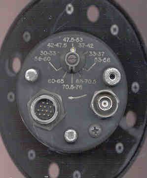 |
Showing:
- Clockwise only band switch 30-33, 42-47.5, 47.5-53,
37-42,
33-37,
53-56,
65-70.5, 70.5-76, 60-65, 56-60 Notice that the
bands are not in
order.
- 12-pin connector PCI U-291/U The radio connector
would
be the
12-socket
version.
- BNC(f) connector with a protective tube around it.
- Drain Screw - put in a straw, coffee stirrer, or
somethng to
break the
vacuum once every few months to get the water out!
|
|
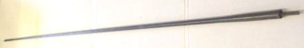
AT-1095 Upper antenna element
|
|
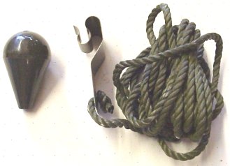
Tie Down Kit - |
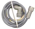
|
CX4722A/VRC (20 Ft. 0
in) cable
NSN 5995-00-985-8090 CAGE 55928 (3/93) has a 12-socket
connector
U-290/U 0CS66 that mates with the MX-6707 and a right
angle
12-pin
connector that looks like the one on the base of the
MX-6707.]
Looking into the plug the pins are:
B
A C
D E F H
J K L
M N |
 |
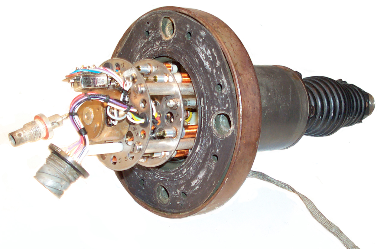
The
photo to the left showes the inside of the MX-6707 after the
bottom
cover has been removed. In order to take off the
bottom cover all
the connector nuts, the knob,and the nut under the knob need
to be
rermoved BEFORE removing the scrows that hold the bottom
cover to the
flange. |
|
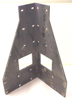
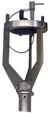
SCD-189023 Scoop
mounting
base. Common 2" muffler "U" bolts fit the existing
holes so it
can
easily be mounted to a fence post or pipe. |
|
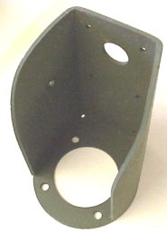
SCD-446058
Corner bracket, Typically
installed on the rear corner of vehicle. |
|
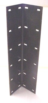
Extender for SCD-446058 used
to
raise the antenna base up. Important for higher power
(more than
5 Watts?) so that someone will not ge as likely to get an RF
burn. |
 |
Antenna Adapter (NSN
5985-089-5020)
See Mounting below
|
3.0 Operation Instructions
3.1 DC Resistance of Antenna
The DC resistance looking into the BNC connector is an open
circuit for
all bands except for the 70.5-76 MHz band where it is a
short.
This
means that this antenna can not be used with a direct connection
to
a PRC-126,
etc. radio that requires a DC path to ground in order to sense
that a
50
Ohm antenna is connected.
It should work with a any of the radios in the PRC-68 family when
my 68AA Antenna Adapter is used
becasue the
adapter supplies the DC return
needed for the PRC-126 or PRC-128 (low band in this case).
It does work with the OF-185 in
either
the
AMPL or BYPASS modes.
3.2 Mounting
For military vehicle mounting there are standard brackets that
bolt
on the vehicle. There are also extension brackets that raise
the
antenna base both to keep bystanders from getting RF burns and
also to
increase the range.
There
is also a mast adapter that allows the AS-1729 to be mounted on a
GRA-4 or RC-292 mast. This adapter has 4 holes that appear
to be
for ground radials, but they are not threaded for the AB-2 or
MX-116
type elements. What goes there? ans in AB-903 TM, 4 counter
poise
tubes (snap into the unthreaded holes) and then a wire is
connected to
the tips of the tubes froming a square shape.
The Antenna Adapter (NSN 5985-089-5020) is used with the AB-903
(NSN
5985-933-2197) 30 foot crank up mast. Both made by FSCM
81868. See TM 11-5985-263-15 for the AB-903 which includes
the
Antenna Adapter. It's also called a "counter poise adapter
unit"
and it's stated that it's for only the MX-6707 matching unit base.
The adapter has two permanent pins and two "T" head bolts to allow
attaching the AS-1729, or probably any other antenna base that
uses the
standard military 4 bolt pattern.
Some ground radials or a counterpoise system probably should be
used
when the AS-1729 is mast mounted.
Pole adapter for MX-6707 - this bracket weighs just over 1 pound,
it
must be made of
Al.
The CX-4722 needs to be fed through the bottom of the bracket and
mated
to the MX-6707 before the MX-6707 is attached to the
bracket. The
MX-6707 can only be installed in 1 of the 4 possible positions so
that
the cable will be in the notch on the bracket.
Needs Ground
When VSWR testing the MX-6707 the specification MIL-A-55288C calls
for
mounting the base in the center of a 10 foot square sheet of
copper. So for best performance the base needs a good
ground. I tried to test the AS-1729 with the base just
sitting on
the ground and got poor VSWR.
For now I am going to use a narrow bandwidth Hamstick 9106 on a
Diamond
K400-3/8C 2-axis adjustable mount for drive testing the OF-185.
3.3 Remote Antenna Band Selection
Using a BA-2 or 22.5 Volts DC with negative connected to pin C
(Red)
|
Band
|
Positive to
|
MHz
|
CX-4722 color code
A= Black
|
|
A
|
A & D
|
30-33
|
Green
|
|
A
|
A & E
|
33-37
|
Orange
|
|
A
|
A & F
|
37-42
|
Blue
|
|
A
|
A & H
|
42-47.5
|
White/Black
|
|
A
|
A & J
|
47.5-53
|
Red/Black
|
|
B
|
D
|
53-56
|
Green
|
|
B
|
E
|
56-60
|
Orange
|
|
B
|
F
|
60-65
|
Blue
|
|
B
|
H
|
65-70.5
|
White/Black
|
|
B
|
J
|
70.5-76
|
Red/Black
|
Other Pins are:
|
Pin
|
Wire Color
|
|
B
|
White
|
|
L
|
Orange/Black
|
|
K
|
Green/Black
|
|
N
|
Balck/White
|
|
M
|
Blue/Black
|
Pin C is the negative grund pin
Pin A is bank select, set to +22.5 for 30 - 53 MHz, open for 53
- 76
MHz
D,E,F,H, & J are sub band selects
N is always +22.5 (or +25) when the MX-6707 is operational (note
on
some vehicle mounts this there is a jumper so that you dont
drain the
vehicle
battery).
B, L, K, & M are not used
Reference Information
Manuals
054769.pdf TM 11-5985-262-24P ANTENNA,
AS-1729/VRC
NSN 5985-00-985-9024
restricted TM 11-5985-262-14
ANTENNA,
AS-1729/VRC NSN 5985-00-985-9024 - has the schematic diagram
and
testing methods.
TM 11-5985-262-15 Maintenance
Block Diagram of MX-6707 -
Notice
that the BNC coax center conductor goes to the center antenna
terminal
and
also goes through a network that is switched and then to the outer
sleeve
of the antenna.
Schematic Diagram - from TM
11-5985-262-14
Testing 7 June 2004
I attempted to plot the VSWR using the 4395A, but the
VSWR looks poor in the 30 to 50 MHz range and is better from 50
to 76
MHz. Not sure why. Maybe need to have the antenna in
a
vertical position or may need a ground plane. Tried a
ground
connection to the ground strap, but that didn't make too much
difference. When the AM-2060 switch changes the MX-6707
now
spins to match the band select position. Usually either a
full
turn minus one notch or one step.
The theory of operation for this antenna is not clear. The
lower
section seems to be a coax extension for the upper section.
Opening the Bottom Case
- Remove both the coax and band select cables
- Remove MX-6707 from any mounting bracket
- Remove the band select knob using a "-" screwdriver, not
that
there is a groove that aligns with the pointer side of the
knob so you
can put it back on correctly. The pointer and the knob
position
should match the position set remotely.
- Remove the nut that's under the knob. This nut is
threaded on a plastic shaft that's easy to break so be
gentle.
- Remove the nut securing the band select connector
- Remove the nut securing the BNC(f) coax connector
- Remove the screws holding the base to the rest of the
MX-6707
using a "+" screwdriver.
- The metal cover is located with a couple of pins, but it's
a
good idea to mark the cover and MX-6707 so you know how to
put the case
back on.
- Lightly tap the band select connector and BNC connector
and
pull the cover off.
Patent
2913722
Broad Band Vertical Antenna, H. Brueckmann (Army) Nov 17 1959, 343/724
; 343/729; 343/830; 343/861; 343/876 -
20 to 70 Mc two section whip
where low frequencies are fed to bottom but higher frequencies
are fed
to center of whip. Uses switching and remote control maybe
the MX-6707?
3100893
Broad Band Vertical Antenna with Adjustable Impedance Matching
Network, H. Brueckmann (Army), Aug 13 1963
uses a 4P3T swtich
3212093
Center-fed Whip Antenna, H. Brueckmann (Army) Oct 12 1965, 343-724
-
antenna will continue to radiate
after whip has been broken
2700733
Nonreasonant Antenns, H. Brueckmann (Army) Jan 25 1955, 250-33.51
- dual VHF rhombic - OE-254?
Related
The AS-2731/GRC, NSN
5985-01-017-0785, as described in TM 11-5985-355-13 is very
similar in appearance to the AS-1729, but has an operating
frequency
range of 30 to 80 MHz. The major components are:
- MX-9146 Matching Base, 10 frequency ranges
- AS-2732 Antenna Element, 5.5' whip
- CX-13055/GRC Special Purpose cable, mates with CX-4722-xx
Web Links
Steve Haney - antennas and
other
mil
radio stuff, recommended by Brooke
PS Magazine #559 pg
48 - Water's
a
Pain, Unless You Drain
Fair Radio Sales
-
Tacticom - Antennas
- Cables -
Component Products - Antenna
-
Shakespear - Mil
Antennas -4242-MK2 broadband, centre-fed, dipole
antenna.
The
antenna base is physically identical to that of the MX-6707 with
the
exception
that it utilizes broadband circuitry that requires neither
mechanical
nor
electrical tuning. The frequency coverage is from 30 MHz to
88
MHz.
The matching is accomplished with loss, but the performance is
about
the
same as the AS-1729?
Trival Antene
-
Kamnik - Sovenija - 0.4 to 3,000 MHz
Telex® Wireless -
Model
4331, 4332 and 4334 VHF Antennas -
TM
11-2300-352-15-5: Installation of Radio Sets AN/VRC-46,
AN/VRC-53,
or AN/GRC-125 in Truck, Cargo, 3/4-Ton, M37 - Drilling
Details for Antenna AS-1729/VRC
Back to Brooke's PRC68, Products for Sale,
Military Autio, Squad
Radio, Military Information,
Personal Home
page
[an error occurred while processing this directive] page created 1 March
2001.