
|
|
|
| OF-185 in
Vehicle |
Front w/o
RF amp |
Rear w/o
RF amp |
1.1 Adapter Group OF-185/PRC (Vehicle Adapter, Power Supply/Audio)
The Power Supply/Audio (PS/A) assemblly conditions the vehicular input power to provide RT and PA operating power. RT battery charging current, and 2 Watt amplified receive audio for a remote speaker. There is a speaker as part of the OF-185. The input power can be 10 to 32 VDC to J6.
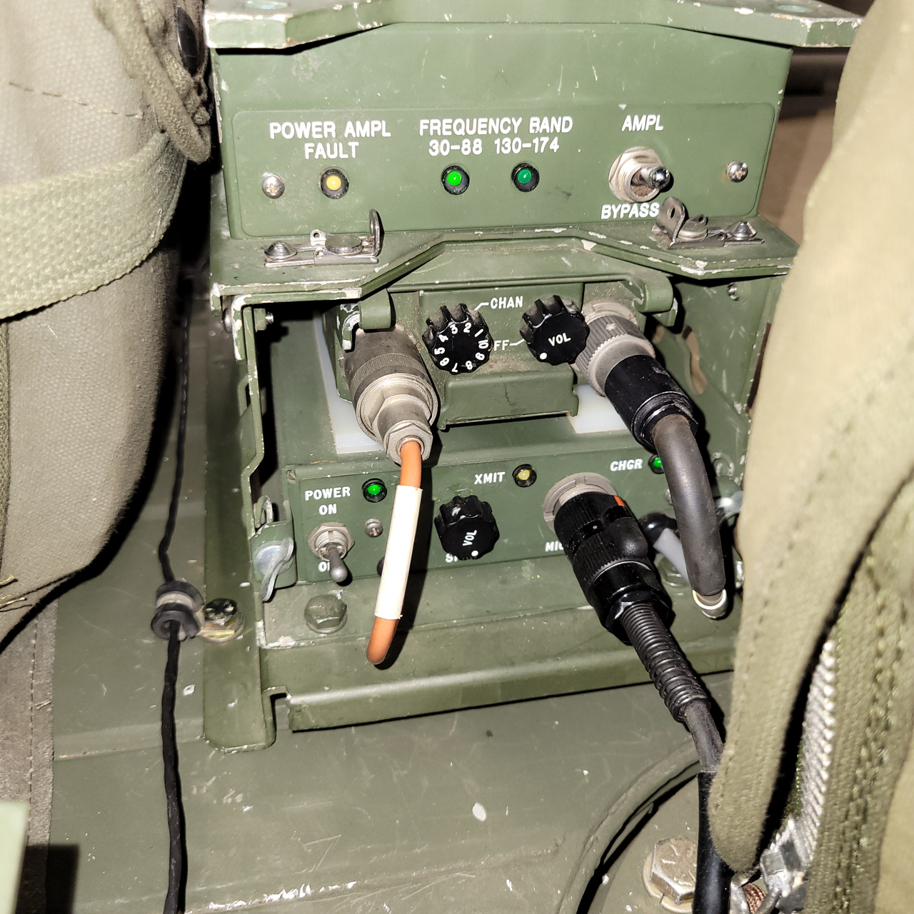
Photo - showing both the Power Supply/Audio, RF amp and PRC-128 mounted between the seats with the bottom near the floor.
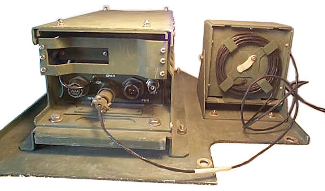
Back of Audio Amplifier and Speaker -
Back of Audio Amplifier -
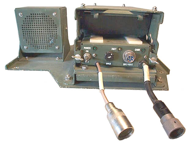
Front of Audio Amplifier -
Front of Audio Amplifier and Speaker - The antenna adapter has the numbers 58167 01186. This is a very good design adapter.
OF-185 ID Plate -
Bottom Inside of PS/A box - the RF cable that connects to the radio ANT is a pass through cable that ends on the back BNC(f) connector. This cable has a shunt DC resistance of just under 2 k Ohms. This is the value needed for the PRC-xxx radio to sense it is connected to a 50 Ohm antenna.J6 - 10 to 32 VDC input. MS3116F12-3S is the connector (Newark 16F3633) on the power cable. p/n 420979-801 is the official DC power cable.
There is another audio amplifier power supply called the OG-174. It can hold radios in the PRC-68 family and has the standard VIC-1 interface connector to connect to the AM-1780.
- A = Chassis Ground
- B = + Vehicle power
- C = - Vehicle power
Dec 2008 - Mike Murphy has a number of the OF-185 boxes without the amp module installed.
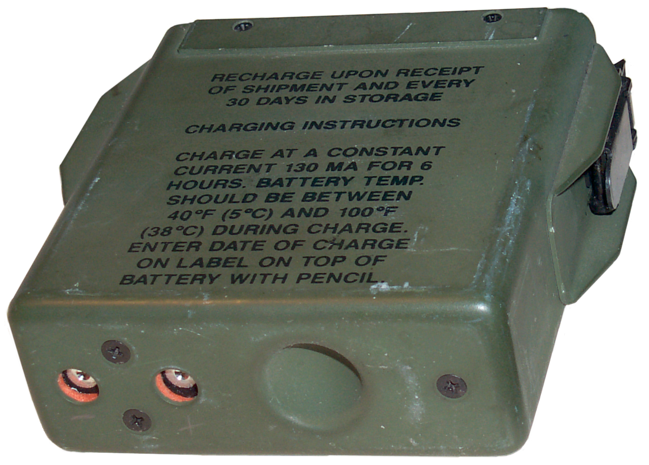
Battery Charging
The mount has provision to charge a special battery while the battery is connected to the radio. The special battery has the charging contacts on the bottom and also has a hemispherical "dent" in the bottom of the pack. The mount has a "finger" that's connected to the charging contacts and if the "dent' is in the battery pack then the charging finger is allowed to move forward and contact the pack. But if a standard battery pack is used, without the "dent" in the bottom, the charging contacts are held back, and so don't make sparks on the bottom of the stock battery.
1.2 Radio Frequency Power Amplifier
The RF Power Amplifier (PA) provides transmit RF amplification of approximately +10 dB (15 Watts nominal output) in the frequency range of 30 to 88 MHz (30 to 88 MHz amplifier/filter installed) and 130 to 174 MHz (130 to 174 amplifier/filter installed). This is a seperate unit that fastens on top of the Power Supply/Audio unit.
- RF Amplifier - RF Amplifier Label -
Front of Amp -
Back of Amp - BNC(m) cable and 10 Pin(m) cable to Vehicle Vehicle Adapter, Power Supply/Audio, BNC(f) socket for coax to Antenna
Label on Amp -
High Band Amplifier - Filter Unit (the Low Band Amplifier - Filter unit is in the amplifier housing
Label on cardboard box holding High Band Amplifier - Filter Unit
These PS/A assemblies show up on the surplus market without the brackets for the RF amp and without the RF amp. By themselves you do get all the features needed for adapting one of the PRC-68 Family radios to a vehicle.
1.2 RF Amplifier
The RF amp accepts either a VHF low band or VHF high band module. It's attached to the PS/A with brackets.
1.2.1Signal Strength
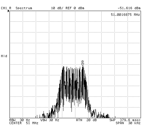
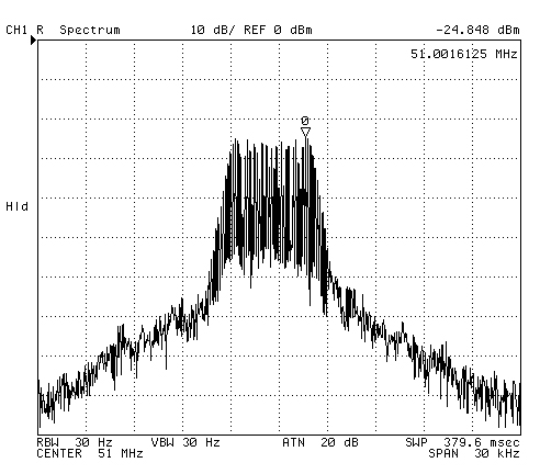
Using the AMPL or BYPASS switch on the RF amplifier and watching the received signal on an Agilent 4395A Spectrum Analyzer shows 15 to 20 dB higher signal with the amplifier turned on. It works! The links below are spectrum analyzer plots where the marker shows the signal strength.
In all cases the receiving antenna is a Radio Shack 20-176 with 100 feet of 75 coax to the Spectrum Analyzer, at 51.0 MHz..
- Inside using PRC-126 #2 Rubber Duck Ant -52 dBm
- Inside using PRC-126#2 9" Goose neck and 36" tape antenna -25 dBm (about the same as OE-254, barefoot for barefoot)
- OE-254 Ant with PRC-126 #1 running barefoot (amp BYPASS) -24 dBm (huge difference from Rubber Duck to Tape ant!)
- OE-254 Ant with PRC-126 #1 Amplified -12 dBm (12 dB gain for Amp)
- Inside using PRT-4A with it's 2' whip -30 dBm (this Tx is tuned slightly high in frequency)
Inside is about 30 feet horizontal distance to receive ant on second story roof.
OE-254 is up about 15 feet and maybe 75 feet from receive ant.The PRM-34 is handy for checking the VSWR of an antenna connected to the power amplifier. The amp puts out about 15 Watts and the PRM-34 measures tenths of a Watt to 50 Watts. My Hamstick is running about 14.6 Watts forward and 0.4 Watts reverse or: VSWR about 1.4
1.3 AN/PRC-128 Handheld Radio
This radio can be used for 30 to 88 MHz operation or 130 to 174 MHz operation depending on which RF/IF module is installed.
These radios are full military specs, they can be submerged in water. The PS/A unit and the RF amp are NOT waterproof!1.4 Current Draw
With just the PRC-126 connected to the OF-185 (Power Amp disconnected) the current draw is less than 1 Amp for receive.
With the power amplifier connected and transmitting the current is about 6 Amps from a 13.6 Volt supply.1.5 Mobile Antenna
I was considering the AS-1729 for my car, but it would be difficult and/or expensive to mount and has efficiency below a 1/4 wave whip.
I am going to try Diamond K400-3/8C trunk lip mount. This has a 2 axis adjustment so that after attaching to a car, or mini van you can get the antenna to point up. The Hamstick model 9106 6 meter antenna will work on 51.0 MHz with more efficiency than any of the military antennas, but has very limited frequency coverage relative to what a PRC-126 can cover. I plan on using this for drive testing.
3.1 Introduction
This system was designed for use in a vehicle, either civilian (12 Volt) or military (24 Volt) with the same connections, no jumpers to change.3.2 Controls, indicators and Connectors
Front of Audio Amplifier - Left to right are:Front of Amp -
- Power ON-OFF switch. Note that the OFF-VOL control on the PRC-xxx radio needs to be turned to full volume. If there is a battery fitted to the PRC-xxx radio that does not have the charging socket on the bottom and you forget to turn off the radio in addition to turning off the radio, the battery will be drained. You DO want to intall an empty battery box on the radio when used in the OF-185 to avoid this problem and the hassle of two OFF switches! You need the empty battery box to make the length correct so that the spring loaded fingers will grab the ears on the PRC-126.
- Power ON Green LED. This indicates that the power is there.
- SPKR VOL adjusts the sound level. If it is not as loud as you expect, you may need to turn up the OFF VOL ocntrol on the radio.
- XMIT Yellow LED - indicates that the PTT switch on a microphone is being pressed.
- MIC/HDST for connecting a microphone like the M-80 or a handset like the H-250. The M-80 seems the better choice for this unit.
- CHGR Green LED indicates that the battery is charged. It may be possible to make a charging adapter for the NiCad batteries that are commonly available so that the battery could be charging while the OF-185 was powered on.
Front (was the Top) of RT-1547/PRC-126
- POWER AMPL FAULT Yellow LED indicates an internam failure in the power amplifier
- FREQUENCY BAND either the 30-88 or 130-174 LED will light to tell you which amplifier has been installed.
- AMPL or BYPASS switch to activate the amplifier or bypass it
- The Antenna and AUDIO connector connect to short cables that are built into the OF-185 PS/A unit.
- CHAN selector - In this configuration the LCD on what was the front of the PRC-126 can not be seen. You need to have a table that tells you the Tx and Rx frequency for each cahnnel.
- OFF VOL control needs to be turned all the way to maximum loudness. You can not push the SQ DSBL button to test the volume.
3.3 Antenna
This is a real problem. The frequency coverage of the PRC-68, PRC-126, etc. is 30 to 88 MHz. This is a huge percentage bandwidth. The military AS-1729, AS-3900 and AS-3916 mobile antennas have some loss in addition to tuning in order to get this type of bandwidth. At the low end of the band the loss can be as much a 8 dB below a 1/4 wave whip at the same frequency. I will be trying the AS-1729.
7.1 Manual
TO 31R2-4-810-3 covers all three of these items, it's title is:
Technical Manual
Maintenance Instructions
with
Illustrated Parts Breakdown
Depot
Radio Set AN/PRC-128, PN 901608-801
RF Power Amplifier, PN 901602-801
Adapter Group OF-185/PRC, 901602-801
Wiki: M274 ½-ton 4×4 utility platform truck
I first saw the M274 at Mike Murphy's home. It's impressive. Also See Military Vehicles: M274
Fig 1
Fig 2
Fig 3
Fig 4
Back to Brooke's Squad Radio, MilitaryInformation, Home page
Page Created 9 Jan 2001.


