 |
|||
 |
 |
 |
 |
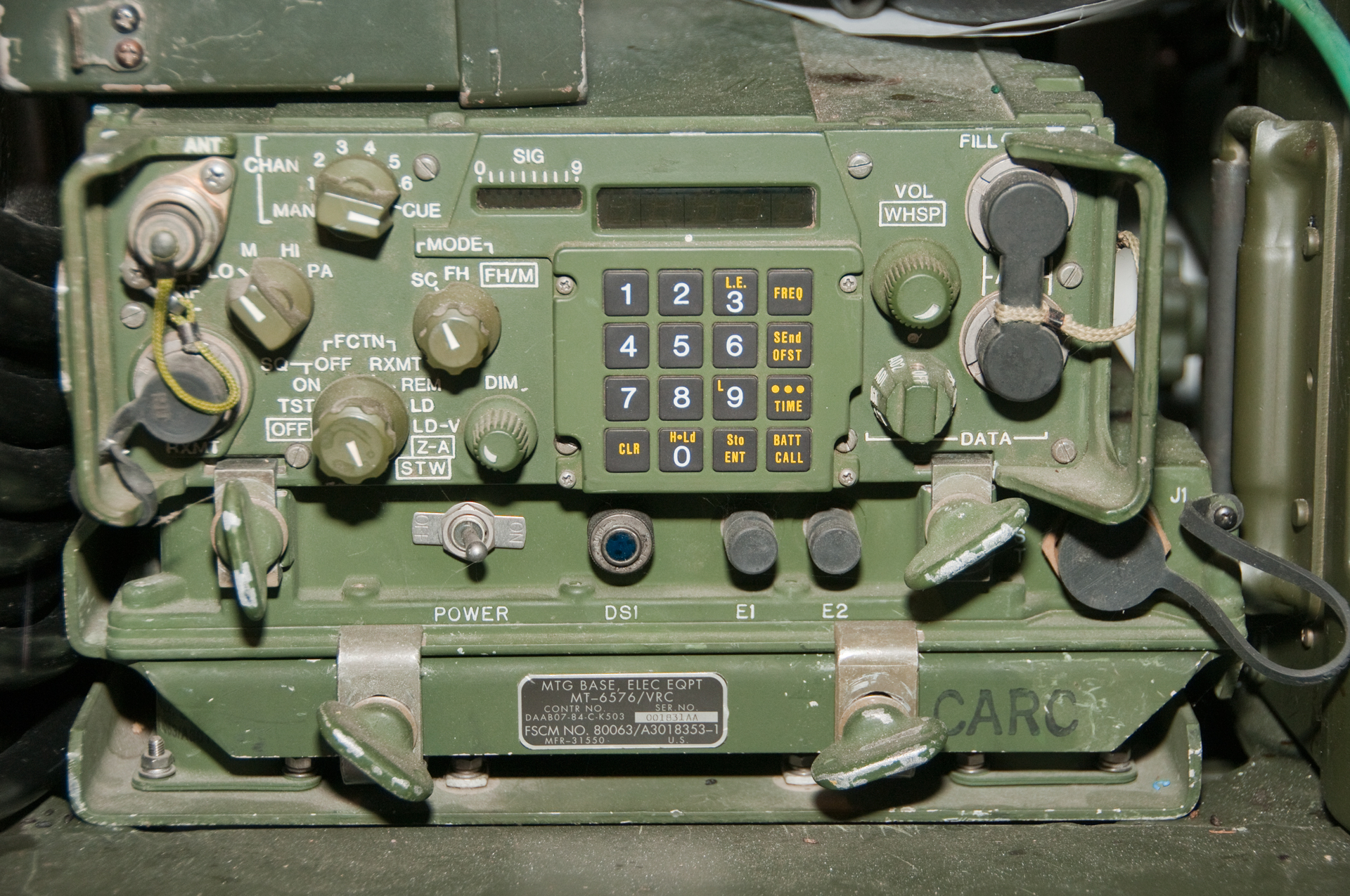
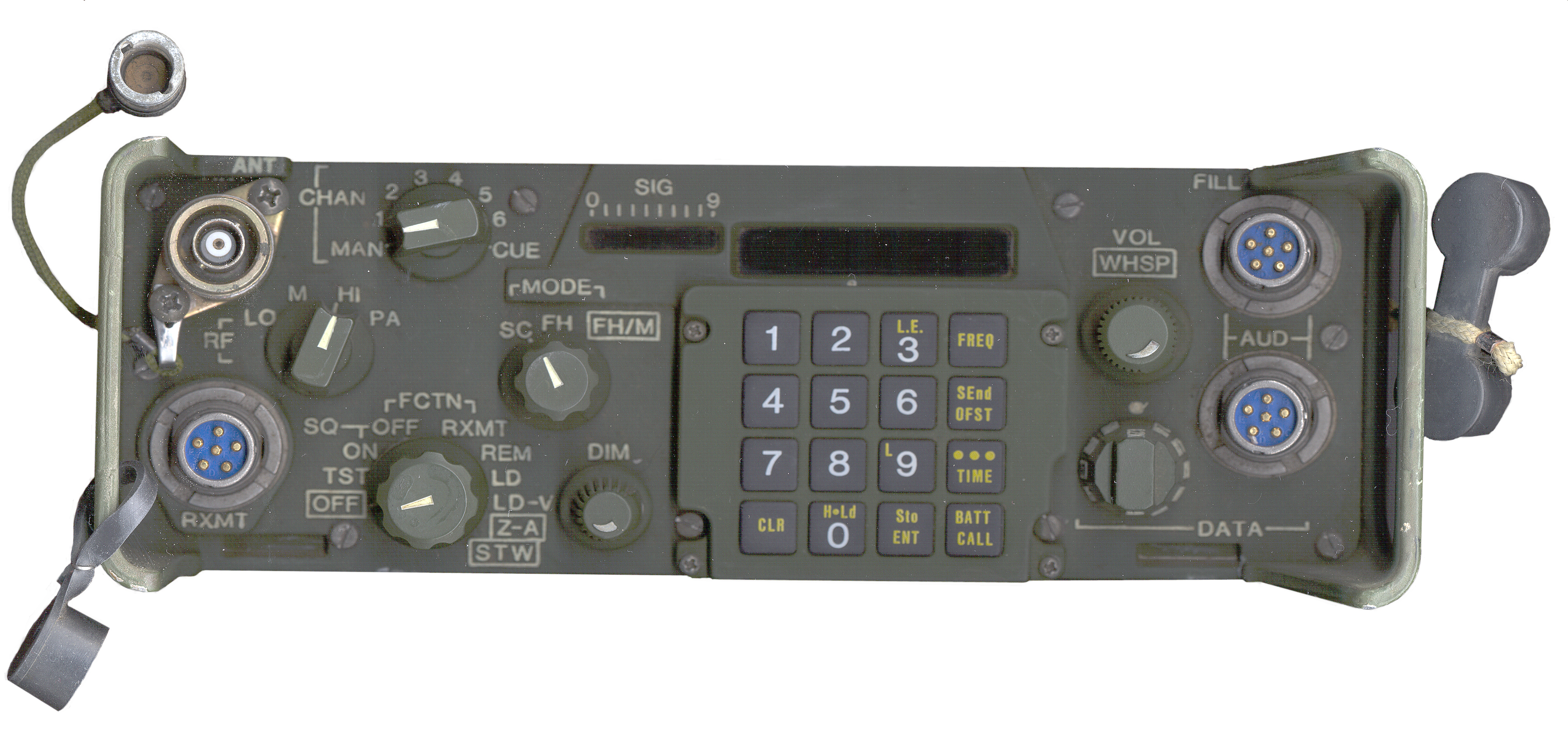
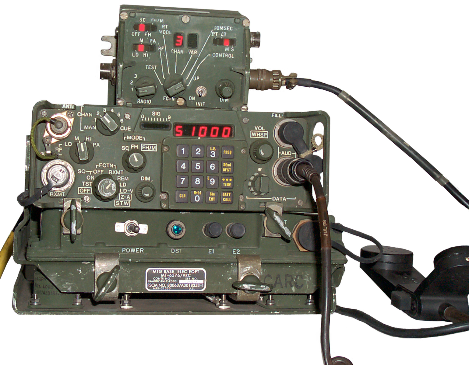
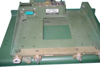
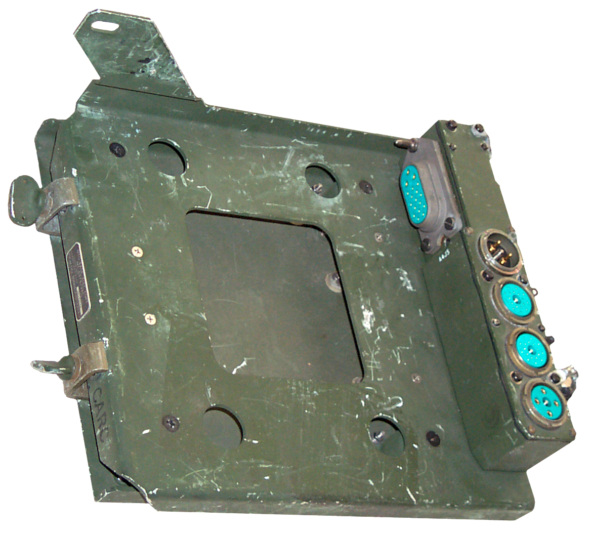
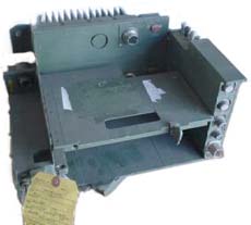
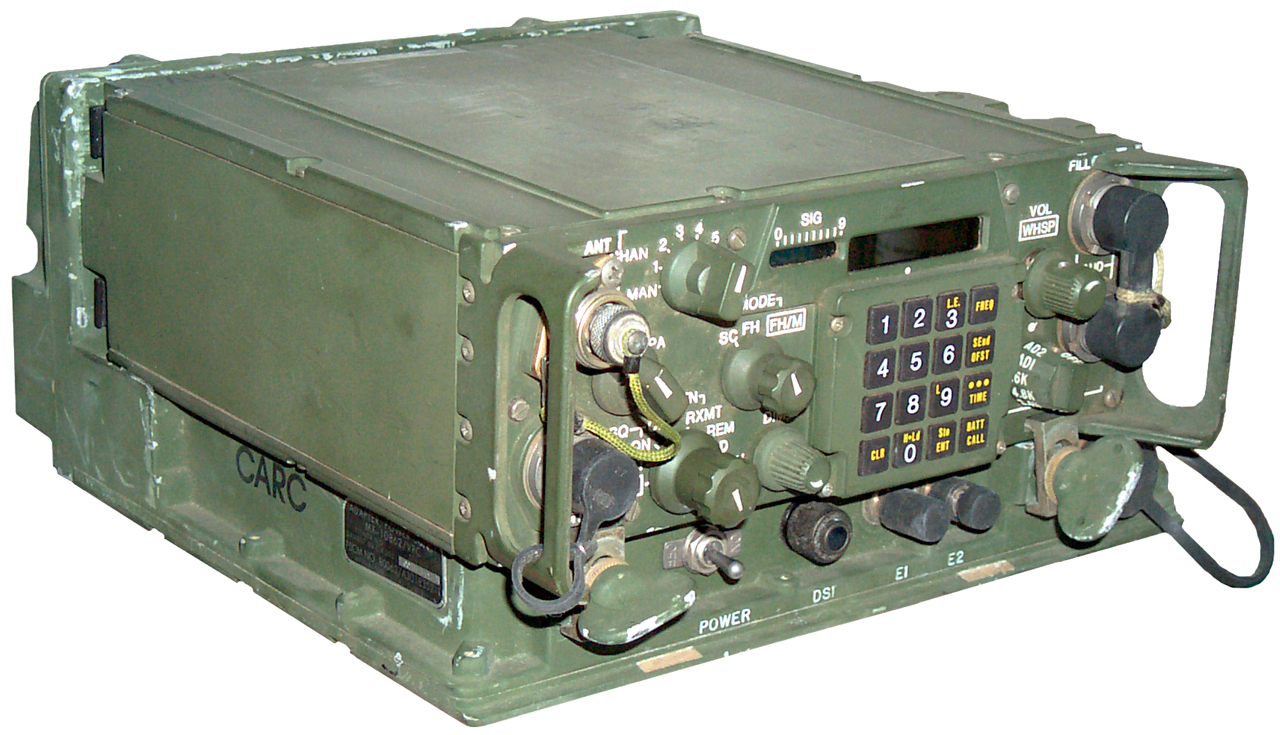
| Front
Panel |
RT-1439
w/o Cover |
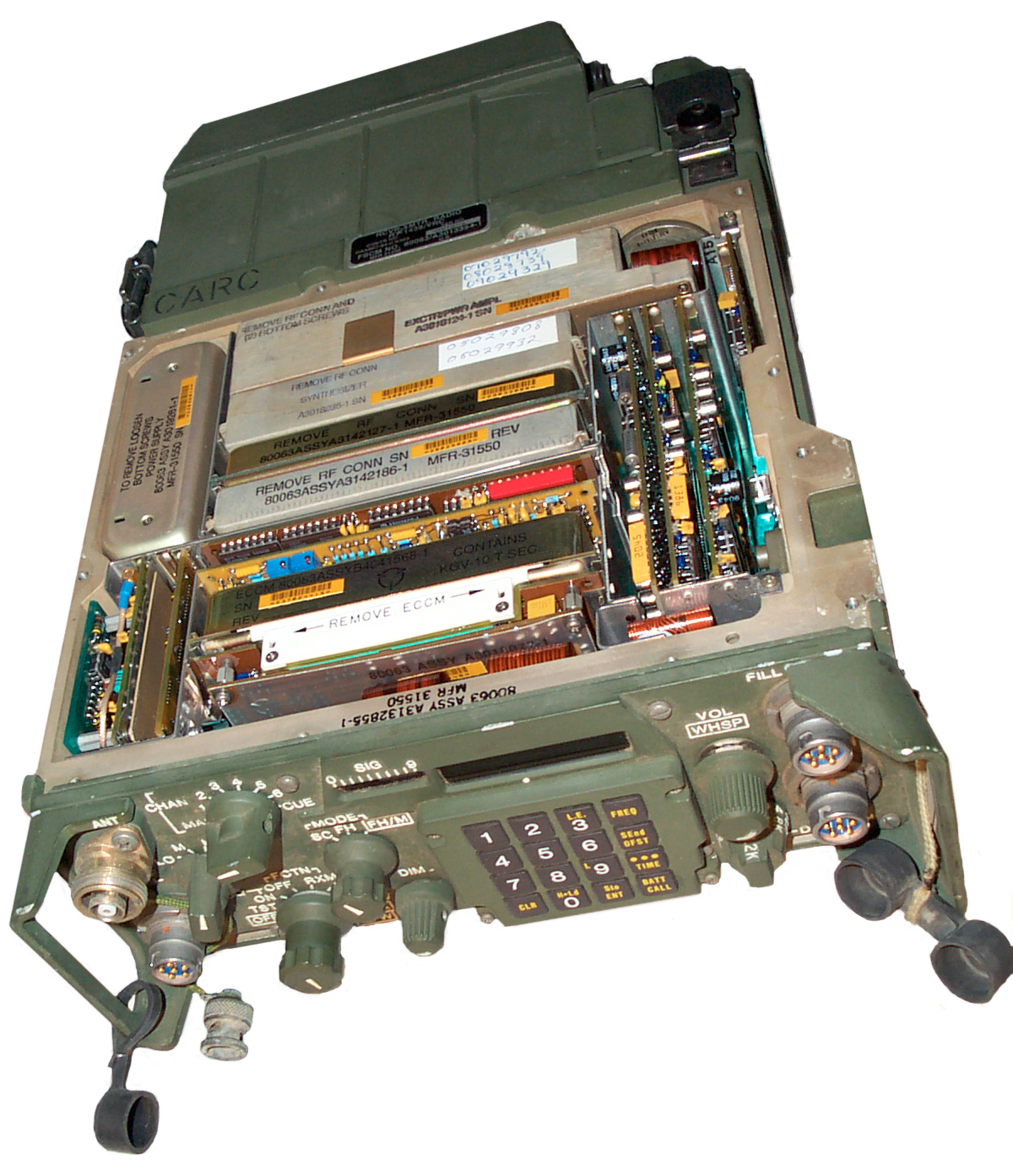
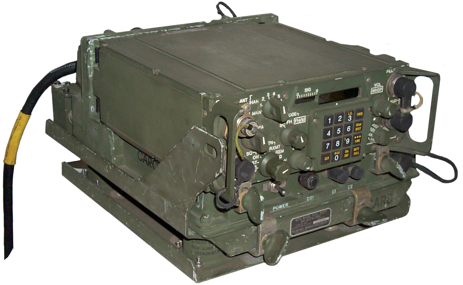
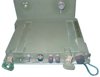
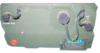
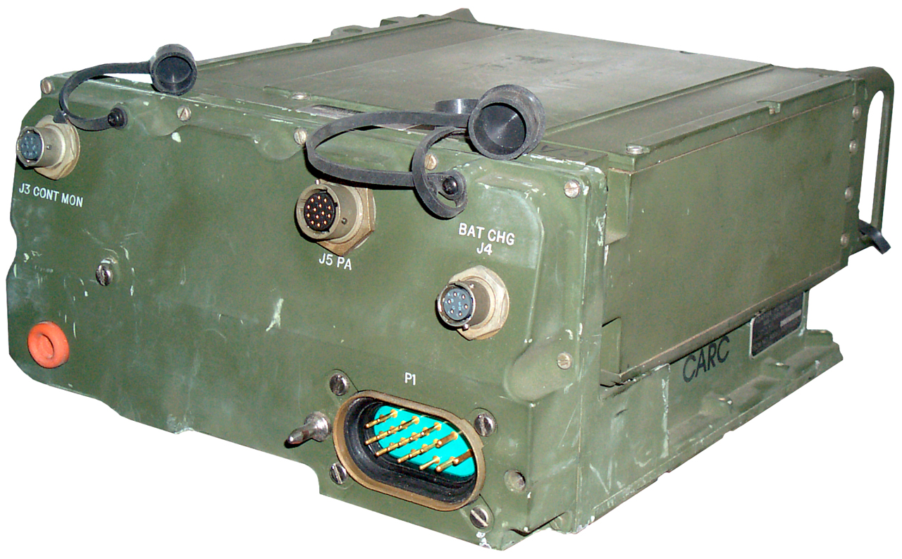
Bottom
w/o Cover |
Ready
for a field pack |
 |
 |
 |
 |
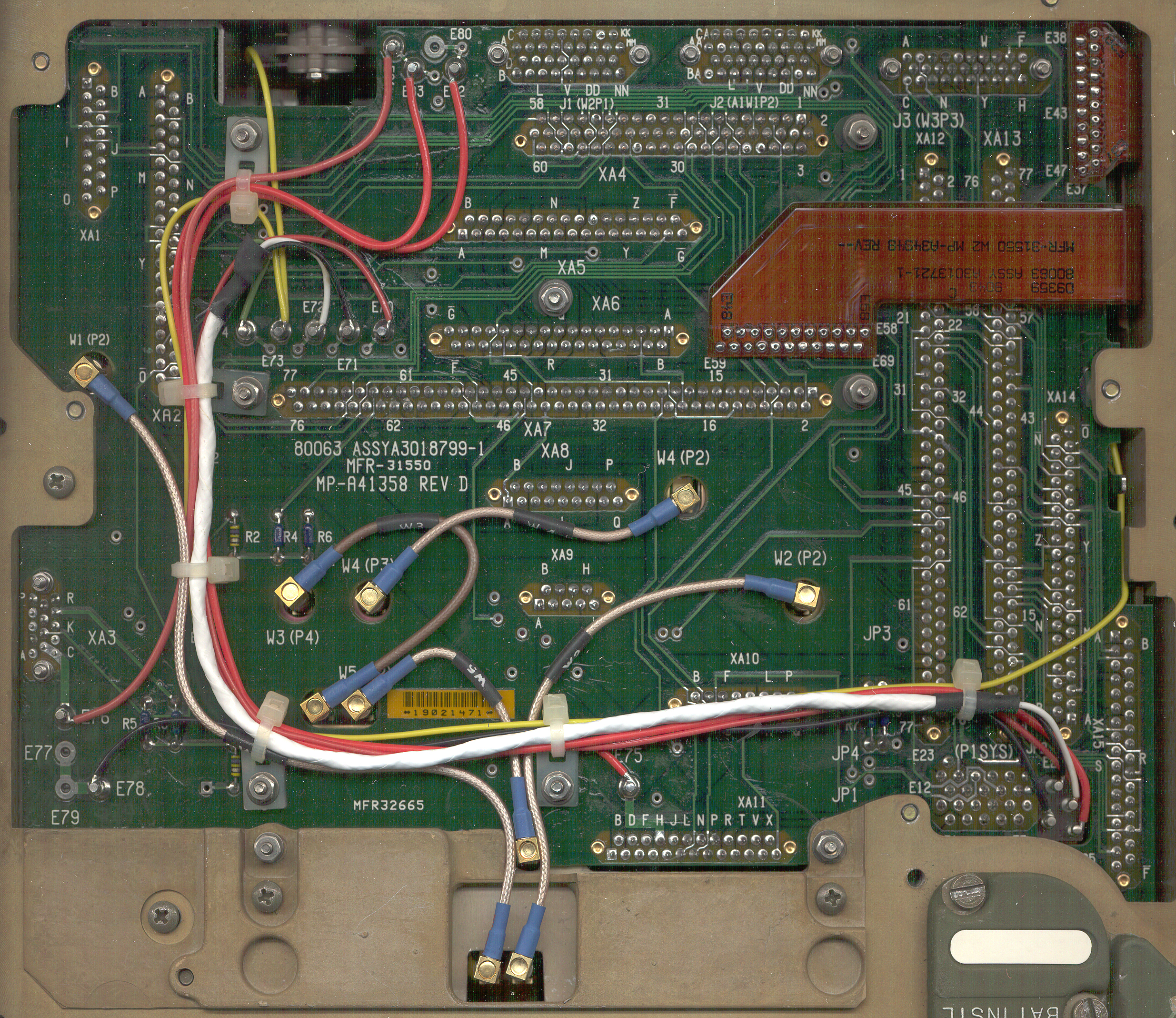
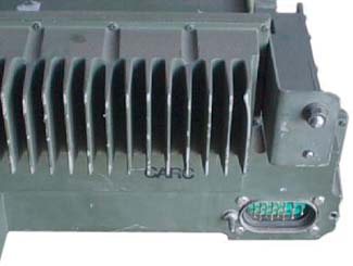
| Rt-1439
Bottom PCB Close Up |
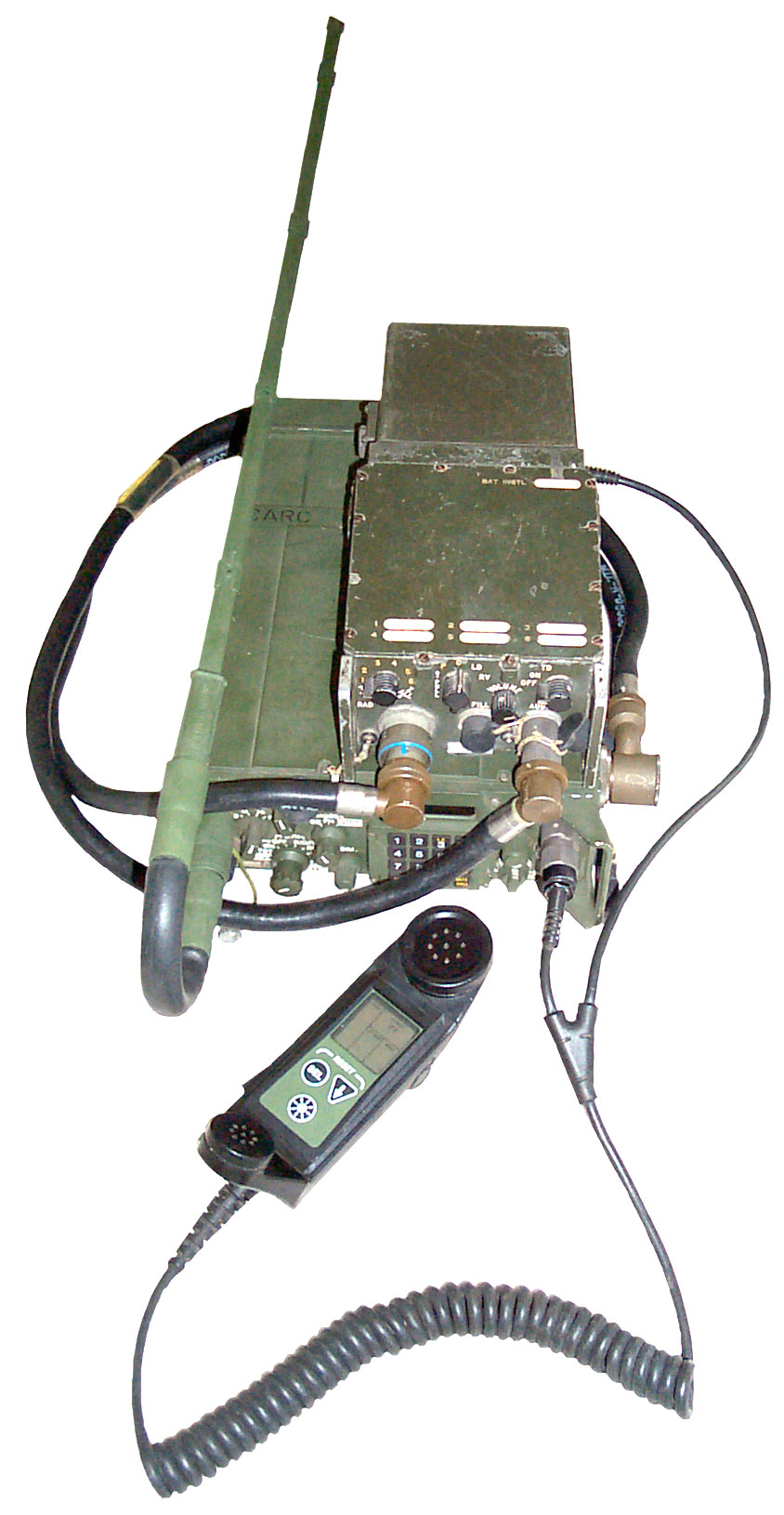
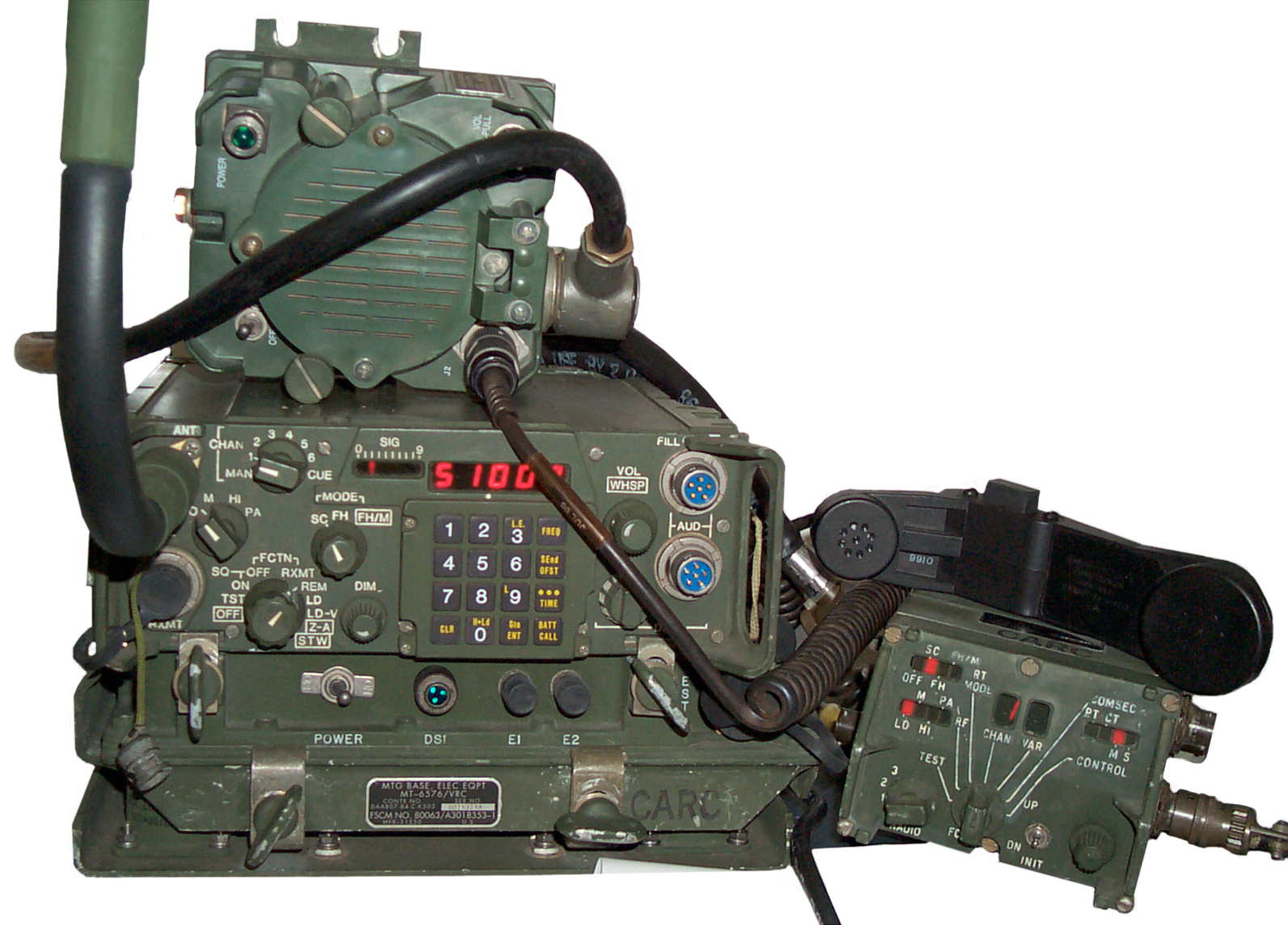
VRC-87
& C-11291 |
RT-1439
& MX-18290 |
VRC-87 |
Frequency Hopping
Communications Security (COMSEC)
Data Modes
Batteries
Scanning
Operation
Self Test
Adjustable Output Power
Leaving Turned On
Squelch
Fill & Joining Net
Displays
Versions & Configurations
Versions
Configurations
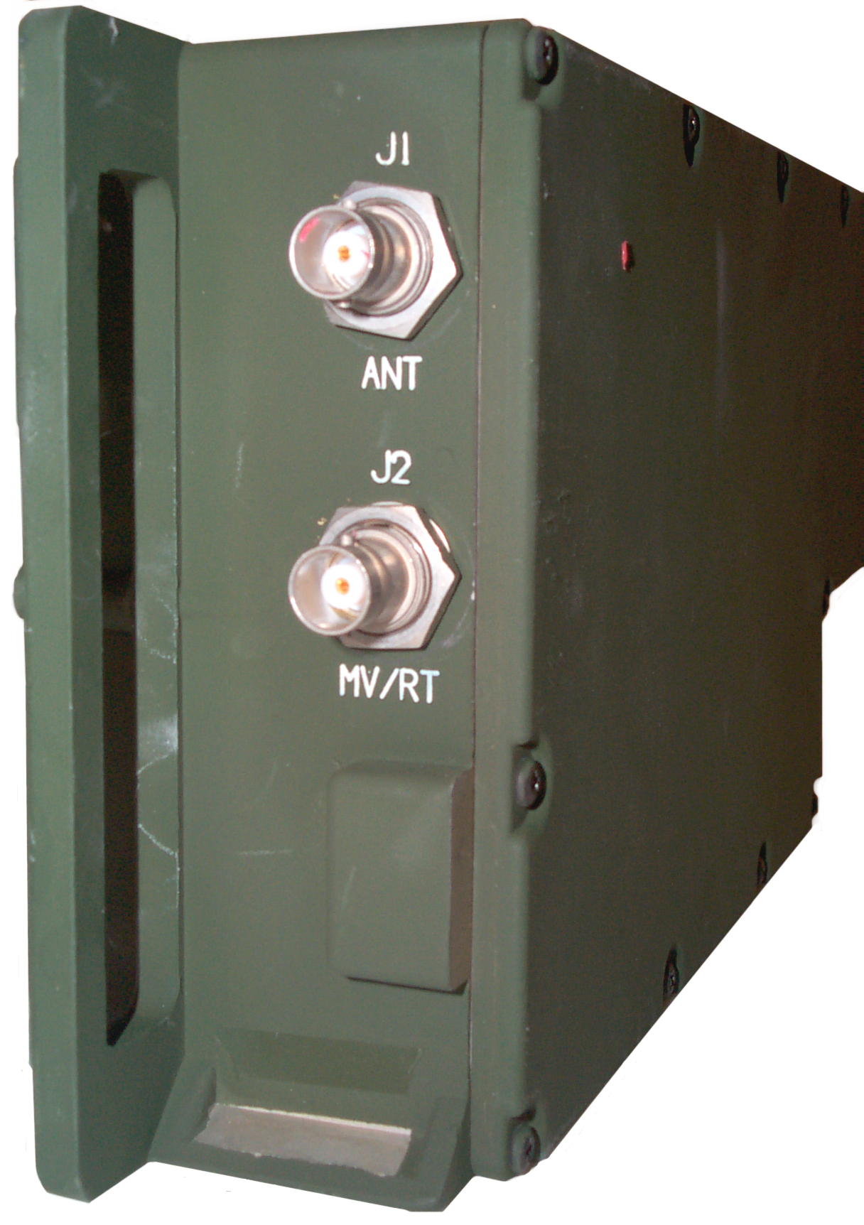
Components
RT-1439 Receiver Transmitter
Modules
System Conn
Antennas
Antenna Connector
AS-3683() Short MP Antenna
AS-3916 Low Profile (SLPA) Ant Vehicular
AS-4266 Long MP Ant
AS-3900 Vehicular Ant
AS-3916
OE-254 Dual Discone
Audio
H-250 Handset
HRCRD Handset - Remote
2-Wire Adapter
LS-671 Speaker, Remote Handset & Master DC on-off
CX-13292 Speaker Cable
Series 5200 Padlock
LS-688 Speaker
LS-454 Speaker (be itself)
LS-454 with Special Amplifier
Battery Boxes & Trays
CY-8523 Battery Box
CY-8523A Battery Box
CY-8523B Battery Box
CY-8523C Battery Box
CY-8664 Battery Tray
PP-8249 Battery Charging Tray
Cables
External
Inside Radio
Carry Case
Mounts
MT-6352 Dual Radio PS/A Mount (A13)
MT-6353 RF Amp Mount
MT-6576 Single Radio PS/A Mount
Adapters
AM-7239() Dual Radio Power Supply/Adapter
MX-10862 Single Radio Power Supply/Adapter Tray
RF Amp AM-7238
Remotes
HRCRD (Handheld Remote Control Radio Device) Handset C-12493/U
C-11291 Control-Monitor (C-M)
C-11561 Remote Control Unit (RCU)
Fill Devices
MX-18290
MX-10579
CV-4228
SNAP
Manuals
What Goes Wrong
PS Magazine
Related Equipment
Links
Background
This web page is newer than the SINCGARS web page and eventually they will be different, but for now there may be some duplication.
Comparison with PRC-77 (with battery box & battery)
| PRC-77 |
RT-1439 |
|
| H"
x W" x D" |
4 x
11 x 11.25 |
3.5
x 9 x 14.75 |
| weight
lbs |
17
lbs* |
Frequency Hopping (FH)
A major new capability is the ability of the SINCGARS radios
to frequency hop covering the 30 to 87.975 MHz band in 2,320
channels. This is not done as a Transmission Encryption
security measure, like is provided by the KY-57, but to prevent jamming and
direction finding. The PRC-25 & PRC-77 are
susceptible to squelch capture
jamming since they are single frequency at a radios. The 225 to 400 MHz aircraft band radios now use Have Quick which is a similar frequency hopping scheme for the same reason.
MIL-STD-200 - System Design and Engineering Standards For Tactical Communications
MIL-STD-188-242 Interoperability & Performance Standards For Tactical Single Channel Very High Frequency (Vhf) Radio Equipment
contains specific performance requirements for both voice frequency and wideband (digital) channels.
In my opinion,
older DF sets that use a conventional receiver channel will have trouble DFing a frequency hopping radio, but DF sets that use what amounts to a spectrum analyzer can DF a frequency hopping radio, and probably can de-interleave a number of them, so the anti DF part of the reason for frequency hopping is not too strong. Note that SINCGARS uses about 100 hops per second, which is considered a slow hop. It is not a direct sequence spread spectrum system like is used by GPS.Once a FH radio has been located by DFing then it's possible to jam it. Not by knowing the hop sequence, but by listening for each new transmission (like using a very fast spectrum analyzer) and then jamming that transmission, then the next, and so on. So the advantage of Frequency Hopping against a sophisticated enemy has a short life. The next generation radios will probably be either fast hoppers or direct sequence spread spectrum types.
GPS is designed so that all the satellites transmit in the same frequency band and the receivers separate them by using different pseudo random codes that are designed to all be mutually orthogonal. Meaning that they have minimal interference with each other (minimal cross correlation). The SINCGARS radios don't have that capability and so when a number of them are co-located there are times when two nets will use the same frequency at the same time causing a collision. This can become a problem. Note that if the hopping bandwidth is narrowed the anti jam resistance is lowered in direct proportion to the bandwidth reduction, so that's not a good thing to do. It's more probable that interleaved hop sets are used.
Although it's theoretically possible to have an analog voice signal on top of a slow hopping carrier it's not as good as using a digitized voice (or data) signal on top of the slow hopper. This way there can be some overlapping and redundancy in the digital data, similar to what's done on a music CD that can tolerate a small scratch. In the SINCGARS it's called forward error correction.
The ECCM module works in two ways. One relates to choosing which RF frequency is to be used and the other related to converting from analog voice to digital and back from digital to analog.
In order for frequency hopping to work each radio in a network must be setup with the parameters that allow all of them to work together. The channel hop set determines what frequencies will be used and is selected in positions 1 through 13 of the MX-18290 Fill Device. The Transmission Security Key (TSK), T1, T2 or T3 on the MX-18290, provides the key to be used by the pseudo random generator to determine in what order the hop set will be used. There is also a provision to have a list of excluded or protected frequencies that will not be part of the hop set.
The Date and Time must also be set to within about a second in order synchronize the hopping. This can be done using the PLGR GPS receiver or can be done manually if the time is accurately know. In a practical net the Net Control Station (NCS) sets the date + time in the channel used by the net stations. Each of the 6 channels can have a different "net time". The channel "ID" number is an offset into the period of the hop set. So there can be a number of different nets all using the same hop set and TSK and set to the same date & time.
The various keys are loaded using the AUDIO/FILL connector and can also be loaded over the air if a higher level Key Encryption Key (KEK) has already been loaded into the radio.
Communications Security (COMSEC)
COMSEC is handled on the RT-1439 using the same KY-57 that was used with the PRC-77 and/or VRC-12 Series radios. And when the RT-1439 is used in the single channel mode it can inter operate with a PRC-77 in either plain text or secure modes. Later models of the SINCGARS radios have internal COMSEC (KY-57) capability (ICOM). Note that the MX-18290 can not load the KY-57 key so a separate Fill Device is needed for that or the key can be loaded over the air.Data Modes
Although the PRC-77 can handle 16 k bits per second digital data it can not accept any of the common digital data connections that a PC can use. The SINCGARS radios have a AUDIO/DATA connector that directly supports a number of synchronous and asynchronous data modes. These data modes can be audio tone based like a fax or modem or can be digital signal levels like from a teletype machine or a computer serial data port. The System Improvement (SIP) and Advanced SIP (ASIP) radios support RS-232 data and Internet Protocol (IP) data packets.Batteries
Main
The PRC-25 and PRC-77 used the BA-4386 style battery (or my 257477BA Battery Adapter). But as part of a U.S. military battery standardization program the SINCGARS radios (and many many other military electronics devices) use the BA-5590 (or my 5590BA Battery Adapter), or any of the rechargeable versions (BB-390, BB-590, BB-2590, etc.). Note that the CY-8523() Battery Box connects the battery as a "12 Volt" battery rather than as a "24 Volt" battery. This means that a SINCGARS radio can be powered from a civilian "12 Volt" motor vehicle, but not when in a Mount that needs military vehicle "24 Volt" power.The RT-1523A and RT-1523D (EGTN version) will not properly work with the Li-Ion BA-2590/U battery. It's 16.5 volts is too much for these radios.
Hold Up Battery (HUB)
The HUB maintains the CMOS memory and clock in the radio when the main battery pack is removed or vehicle power is lost. It also keeps the memory and clock alive when the radio is switched to OFF. But when the FCTN switch is set to Stow (STW) the HUB is turned off and all memory is lost. This is good in that is does not run down the HUB battery when it's not needed.
Unfortunately the labeling of the Function switch is backwards between the RT-1439 and the RT-1523() radios. On both radios when the FCTN switch is fully CCW (called OFF on the RT-1439 and STBY on the RT-1523) the HUB battery is maintaining the clock and all the channel fill data. On both radios when the FCTN switch is turned full CW (called STW on the RT-1439 and OFF on the RT-1523) the HUB battery is disconnected saving the battery but erasing all the memory and stopping the clock. So the instructions in the Aug. 1998 PS mag article on pg 48 apply only to the RT-1523 radios.
Note the HUB battery has a negative tit unlike most common batteries. It's a 6 Volt battery so trying to substitutive a 3 Volt BA-5123/U or some other battery just will not work.
For the RT-1439 used in a vehicle mount it's a good idea to add a label to the front panel with the HUB battery install date. This avoids taking apart the system just to see the date and rebuilding the system if a battery change is not needed. The correct interval is every 6 months. Ref June 1998 PS mag pg 48. Mar '94 & PS mag 496 pg 36.
The RT-1523E can use Battery holder NSN 6130-01-462-4442 and four common AA batteries for the HUB function.
Scanning
Operation
Self Test (TST)
Preparation
Before running the self test the Antenna and Hand set should be removed. (PS Mag March 2001 issue 580 pg 46) either one may cause signals to be present that the self test does not allow for. (Might cause a FAIL 1)The Data Rate knob should be set to OFF. (some positions will cause a FAIL 2). This happened when I first got the radio and now after using it this no longer happens. Not sure what's going on.
Normal
Results
| Fail
# |
Meaning |
| 1 |
Receive
Path Test |
| 2 |
Data
Rate Adapter |
| 3 |
ECCM
Module |
| 4 |
Rem
& wire line |
| 5 |
COMSEC
(not in CT) |
| 6 |
System
conn (SNAP/FHMUX) |
| 7 |
Routing
Module |
| 8 |
Routing
Module |
Diagnostic
TM 11-5820-890-30-5 Chapter 2 has some information on how to interpret the self test results, but seems to be missing the diagnostic 2--nn and higher number messages. If you have that manual please let me know. In general all the 890 series manuals are very poor regarding explaining what the FAIL # messages mean, especially ones where the operator could correct the failure.
Adjustable Output Power
| Freq
MHz |
LO 0.5 mw |
M 160 mw |
HI 4W |
| 30 |
-65 |
-39 |
-26 |
| 40 |
-69 |
-45 |
-32 |
| 51 |
-58 |
-32 | -21 |
| 60 |
-74 |
-47 |
-34 |
| 70 |
-67 |
-43 |
-32 |
| 80 |
-62 |
-36 |
-23 |
The signal is not a single carrier when no audio input is fed to the mike since the radio is sending a 150 Hz tone. Deviation is about 7.5 kHz without any audio input. The channel frequency is right on at 51 MHz.
The current draw for the "HI" power position is more than 3 Amps (it trips the over current limit on the BK Precision 1786 P.S.).
Leaving Turned On
When Powered from a Vehicular mount the display time out is disabled and the display stays lit. Brightness can be controlled by the DIM knob.
Squelch
Fill & Joining a
FH Net
 No Fills are needed for Single Channel
operation. In order to Frequency Hop there are different
amounts of fill required depending on the circumstances.
No Fills are needed for Single Channel
operation. In order to Frequency Hop there are different
amounts of fill required depending on the circumstances.The simplest case is that you are a member of a net (and not the Net Control Station). Then all that's required is to load the CUE and MAN single channel frequencies as well as the net's Transmission Security Key and request an Electronic Remote Fill (ERF) from the NCS. The NCS can load the hop set (with lockout set if needed) and the correct net time remotely. These can then be stored into one of the channels (typically chan 1 for your local net). This is the same procedure that's used for a normal net opening.
If your radio already has the TSK and hopset for the net and the clock for the net channel is reasonably accurate, then you can do a late net entry by setting the radio just like when it's part of the net and pressing "3-L.E." (Late Entry). This causes your radio to search in time to exactly match the net time and when in sync the frequency display will change from LFnnn (Late Frequency hop set nnn) to just Fnnn (Frequency hop set nnn) and if there's net traffic you will hear it. This will not work if your radio's clock is too far off or if the net ID number or any of the fills is not correct.
Fills
Prior to filling load the MAN and CUE single channel frequencies.Fill TSK
Mode = FH
Connect fill device, select T1 or T2, power on
Connect Fill cable, note display shows FILLE
Press "0 H*Ld", note display shows LOAD
If there's a problem the display shows bad, or if the fill was OK the display shows GOOd
Fill Hop Set or Lockout Set
Mode = FH
Connect fill device, select 1 through 13, power on
Connect Fill cable, note display shows FILLE
Press "0 H*Ld", note display shows LOAD
If there's a problem the display shows bad, or if the fill was OK the display shows GOOd
Time & Date
FCTN = LD
Press "TIME" and enter the Julian day number (1 to 99) based on the table in the back of the manual (note there are two tables, one for normal years and another for leap years), press "Sto Ent", enter the 2 hours digits, press "Sto Ent", (This last press sets the seconds to 00).
1 Jan is always 01, 28 Feb is always 59, Feb 29 is 60, 1 March is 60 in a regular year and is 61 in a leap year, and all the rest of the days follow. 27 Oct in a regular year is day 00, and in a leap day 00 is Oct 26.
PLGR AN/PSN-11 GPS Time & Date Set
TM 11-5820-890-10-7 which includes the PRC-119A (RT-1523) has a Task 3 "Load PLGR Data and Zulu Time into SINCGARS RT". There's no mention that the RT-1439 does not support this fill, but when I try, it does not work. (error in PLGR says radio not responding).
FM 11-1 says PLGR only works with RT-1523A and higher letter radios and the ARC-201A. MX-10579 can only load FH data into the RT-1439 and the ARC-201 (not any of the RT-1523 series radios and not the ARC-201A).
TM 11-5820-890-10-3 which applies to the PRC-119(no letter), i.e. to the RT-1439, describes how the NCS is to either manually set the time and date or use Electronic Remote Fill from another network, no mention of using a PLGR.
This procedure worked on the RT-1523C to load date and time from PLGR:
Set the radio to SC and set to CT.
Select SINCGARS under the MENU key of the PLGR, select ACTIVATE on the PLGR,
then LOAD on the RADIO.
LOAD displays on the radio, and PLGR displays SUCCESSFUL TIME FILL.
Sure enough had the correct julian day on the radio and UTC time.
Displays
Frequency
As the CHAN switch is moved from MAN through 1 - 6 to CUE in SC mode (FCTN any pos) if there are no frequencies loaded the display will show: 30000 (default MAN freq), FILL 1 through FILL 6 and FILL 7. But if the HRCRD is used to scan those same channels the display will show FILLE on all but the CUE channel which shows FILL 7.Below the display between the second and third digit from the left is printed a decimal point that separates the MHz part of a single channel frequency from the lessor digits. The smallest frequency step is 5 kHz, so you can load 30.125, but not 30.123. The SINCGARS are much more restricted than the PRC-126 in that the offset between Tx and Rx frequencies is limited to +/- 5 or 10 kHz in the SINCGARS but the PRC-126 has no restrictions. This limits the flexibility of how the radio is used, for example with the PRC-126 you could program the Tx frequency to be the input to a repeater and the Rx frequency to the the repeater output.
TSK
If the Transmission Security Key has been loaded but neither a hop set nor a lockout set has been loaded the display will show cold.Hop Set
As the CHAN switch is moved from MAN through 1-6 to CUE in FH mode (FCTN any pos) if there are no hop sets loaded the display will show: FILLE on all channels. If there's a Hop Set loaded the display will show Fnnn (Hop Frequency net ID number nnn). If the Lockout set has been loaded but the hop set has not yet been loaded the display will show HLncc.With a Hop Set loaded the display will show Fncc where the first letter is always F the second letter is the hop set ID and the cc is the net ID between 0 and 99. The set starting time can be changed by the NCS when in FH-M mode.
Just after a hop set is loaded the display shows HFncc if the set was a Hop Set or HLncc if it was a Lockout set.
Z-A
A few seconds after switching to Zero-All the display shows good. Meaning that all memories have been erased. Note you need to go through this switch position to get to STW on the RT-1439 (OFF on the RT-1523x) where power including backup battery is disconnected.CUE
The NCS (and alternate NCS) would hear any SC radio sending on the Cue frequency. Another feature of Cue is that if the channel is changed to Cue, then to MAN and back to the net channel, it can passively rejoin the net probably without the wait associated with a passive net entry.
I think that only one station in a net may be set in FH-M mode. This is because the Master station is sending the net time to keep all the net stations in time sync. If two stations tried to do this the times would not match and there would be a problem. The alternate NCS would switch into FH-M mode if something happened to the NCS. If this is the case then all the stations in a net (with that Cue frequency set into their radios) would be aware that a Cue call was in progress, but typically only the alternate NCS would switch to the Cue channel and talk to the calling station, which might be a VRC-12 Series or PRC-77 radio.
The instructions for how to make a CUE call are very consistent in that the calling station needs to turn off voice encryption. and just press PTT (no voice call is being made). Since the calling station does not know when the net is idle the process may need to be repeated several times until an idle time is used for the call. The SINCGARS radio probably detects that there's a carrier on the CUE frequency and alerts the radio operator.
Note that although a SINCGARS radio can store 6 separate channels (6 nets) there is only one CUE frequency CHAN position and so the CUE frequency needs to be manually programmed for each of the 6 channels as does the MAN frequency.
Versions & Configurations
Radio & System Versions
The early SINCGARS radios were developed by ITT Aerospace/Communications Division (31550) around 1988 and second sourced to General Dynamics Land Systems (0HGX3).
The radio version progression has been:
RT-1439 - Non ICOM made by ITT (31550) needs external KY-57
- FM operation in the VHF band (30 to 87.975 MHz)
- 25 kHz channel spacing for 2,320 operating frequencies
- Interoperable with VRC-12 series and NATO requirements
- Single Channel (SC) or Frequency Hopping (FH) mode
- 6 preset channels for FH and 8 for SC (SC can use
the MAN and CUE channels)
- Scan of single channel presets
- Offset tuning of single channel frequencies (+ 5, + 10 kHz)
- Single channel access to hopping nets (CUE’ing)
- 3 RF power settings (500uW, 160mW, 4W)
- Provides control for external 50W RF power amplifier (AM-7238)
- Built-In-Test (BIT)
- ECCM Remote Fill (ERF) of hopping information
- Data Rates: 75, 150, 300, 600, 1200, 2400, 4800, 16000 bps, AD1, AD2 (TACFIRE)
- Majority Logic Forward Error Correction
- Mode 1 Fill
- Volume control/Whisper mode select
- Retransmit (with second SINCGARS radio) (a single
ASIP radio can act as a packet repeater)
- Remote Control capable (via the Securable Remote
Control Unit (SRCU)) (most manuals call this RCU)
- Nuclear survivable (EMP not blast)
- 7 different configurations from Manpack (PRC-119) to Vehicular Dual Long Range (VRC-92)
- Size: 9.3"w x 3.3"h x 14.6"d (includes battery)
- Weight: 18.3 lbs (includes battery)
TM 11-5820-890-10-8 Fig 2-2 RT-1523 Features
TM 11-5820-890-30-4 Chapter 2
RT-1523A- Internal ICOM ( KY-57 built in) increased the run time from 16 to 25 hours per battery. TM 11-5820-890-20P-1 Figure 203, 204
made by GD Land Systems (0HGX3)
TM 11-5820-890-10-8 Fig 2-3 RT-1523A Features
RT-1523B TM 11-5820-890-20P-1 Figure 166 Not much mention in the TMs, so maybe made by GDLS
TM 11-5820-890-10-8 Fig 2-4 RT-1523B Features
RT-1523C/D - Special Improvement Program (SIP) adds more data modes including RS-232 and IP packets to support easy computer interfacing for the Tactical Internet. Also an interface to an external GPS receiver to allow automatic position reporting. This requires an additional connector on the Vehicle Power Supply/Adapters. see FM 6-02.72 Tactical Radios
1523C = TM 11-5820-890-20P-1 Figure 166 probably made by GDLS
TM 11-5820-890-10-8 Fig 2-5 RT-1523C Features
1523D = TM 11-5820-890-20P-1 Figure 205 internal layout very similar to the RT-1439 so probably made by ITT.
TM 11-5820-890-10-8 Fig 2-6 RT-1523D Features
RT-1523E - half size Advanced Special Improvement Program (ASIP) also a single radio can act as a packet repeater (sort of a digital version of a simplex repeater). Uses DSP technology that can be upgraded. The tactical communication system (TCS) handset replaces the HRCRD that displays the operators Lon-Lat and the received stations Lon-Lat. The radio really is a dual channel radio with both voice and digital coms at the same time. Really a new radio. The GPS key controls how the radio transmits GPS data. GPS is set to OFF, voice only (AUTO), periodic (PER), or movement (MOV), and can only be modified in CT. Periodic and movement modes automatically generate short GPS-data-only transmissions.
RT-1523E and Radio sets that use it = TM 11-5820-890-20P-2 all ASIP made by ITT.
RT-1523E(C)/U NSN 5820 01 4441 219
RT-1523F
Improved version of the E
ITT vs GDLS
I've heard that although the ITT and GDLS radios are functionally equivalent the internal construction is completely different and non interchangeable. This means that extra care is needed to correlate the exact model number with the manual when trying to understand the inner workings of a radio. Module layouts. The 1439 and 1523 have the modules both left to right and front to back(LRFB). The 1523A and 1523D have the modules all lined up like books front to back(Book).It maybe like this:
ITT: 1439-LRFB, 1523-LRFB, 1523D-Book, 1523E-half size new radio
GDLS: 1523A-Book, 1523B-Book, 1523C-Book
7 June 2005 - ITT says they made all versions except for the 1523D. Have not yet heard back from GDLS.
- PRC-119 uses RT-1439
- PRC-119A uses RT-1523
- PRC-119D uses RT-1523D
Wheeled
VRC-88 Short Range optional man pack
VRC-89 Long Range - Short Range
VRC-90 Long Range
VRC-91 Long Range - Short Range optional man pack
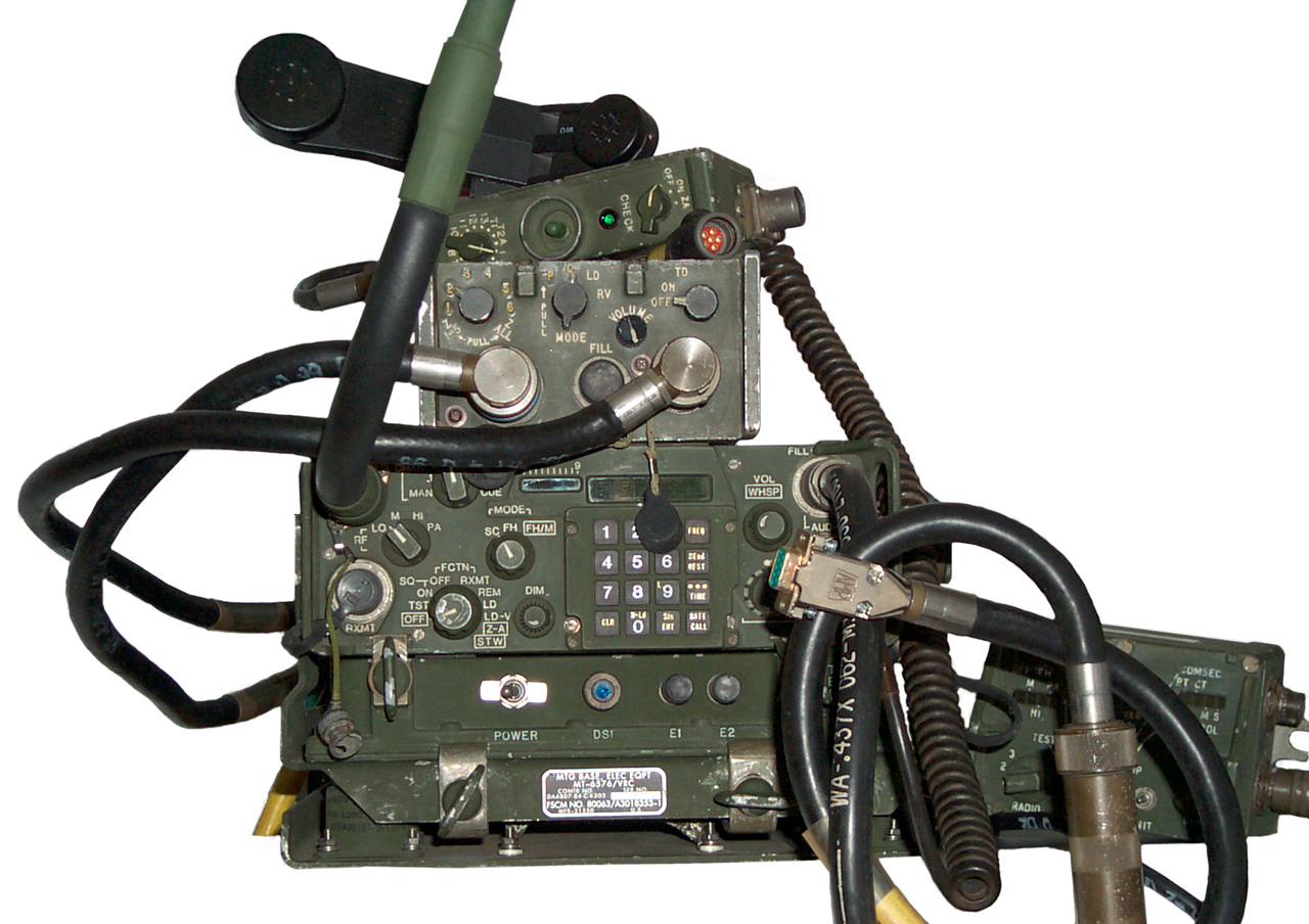
VRC-92 Long Range - Long Range
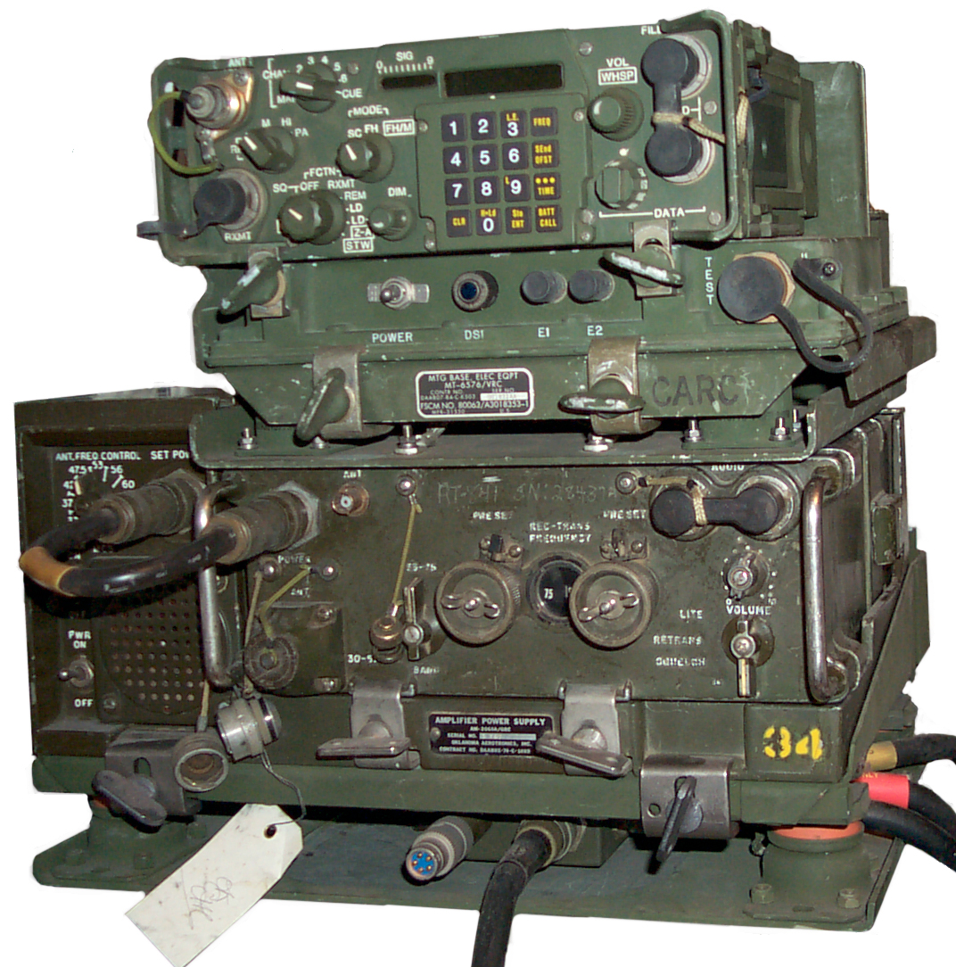
The stack of equipment for SINCGARS is very similar to that for a VRC-64 (PRC-77 in a vehicle).
In comparison photo you can see that the VRC-87 is about as wide as a PRC-77. The SINCGARS radios are narrower, shorter and heavier than the PRC-77(VRC-64).
| VRC-64 |
SINCGARS |
SINCGARS | SINCGARS | Function |
PRC-77 |
RT-1439 or RT-1523() |
RT-1439 or RT-1523() |
- |
Receiver Transmitter Low Power |
| AM-2060 |
MX-10862 PS/Adapt |
AM-7239() PS/Audio Amp |
AM-7238() RF Amp |
DC power conditioning |
| MT-1029 |
MT-6576 | MT-6352 | MT-6353 |
DC power cabling
& /or VIC/TSEC interface |
| Steel mounting shelf | Steel
mounting
shelf NSN 5340-01-215-1044 for HMMWV |
Steel
mounting
shelf NSN 5975-01-413-1547 for M998 |
Steel mounting shelf | Mechanical attachment to vehicle sheet metal |
Tracked
LR = Long Range
-D = Dismount kit for man pack (the -D is different from the D suffix that indicates which radio is used)
| Item | PRC-119 MP |
VRC-87 SR |
VRC-88 SR-D |
VRC-89 LR-SR |
VRC-90 LR |
VRC-91 LR/SR-D |
VRC-92 LR-LR |
| RT-1439 Radio |
1 |
1 |
1 |
2 |
1 |
1 |
2 |
| CY-8523() Battery Box |
1 |
1 |
1 |
||||
| Carry
Case |
1 |
1 |
1 |
||||
| AS-3683() Antenna |
1 |
1 |
1 |
||||
| H-250 Handset |
1 |
1 |
1 |
||||
| AM-7239() Dual Radio PS/A |
1 |
1 |
1 |
1 |
1 |
2 |
|
| W-4 Audio/Data/Fill Cable |
1 |
1 |
2 |
1 |
2 |
2 |
|
| MX-10862 Single Radio PS-Adpt |
opt |
opt |
opt |
||||
| CX-13314 Cable |
|||||||
| AM-7238() RF Amp |
1 |
1 |
1 |
||||
| W-2 RF Cable |
1 |
1 |
|||||
| CX-13291 Cable |
1 |
||||||
| CG-3856 Cable |
1 |
||||||
| CX-13303 Cable |
1 |
||||||
| MT-6353 RF Amp Mount |
Components
RT-1439 Receiver Transmitter (A1)
Modules
| No. |
Description |
p/n |
# pins |
Ltr Num |
# coax |
| 1 |
Antenna
Tuner
BPF |
17 |
L |
1
Bot 1 side |
|
| 2 |
Remote
I/O |
41 |
L |
0 |
|
| 3 |
Main
Power Supply |
14 |
L |
0 |
|
| 4 |
Control |
61 |
N |
0 |
|
| 5 |
ECCM |
33 |
L |
0 |
|
| 6 |
2-wire
Interface |
33 |
L |
0 |
|
| 7 |
Switch |
77 |
N |
0 |
|
| 8 |
IF
Demodulator |
17 |
L |
1 |
|
| 9 |
Rx
Tuner Mixer |
9 |
L |
3 |
|
| 10 |
Synthesizer |
17 |
L |
2 |
|
| 11 |
Tx
Excit & P.A. Rx LPF |
25 |
L |
3 |
|
| 12 |
Audio
P.S. |
77 |
N |
0 |
|
| 13 |
Audio
Control |
77 |
N |
0 |
|
| 14 |
Audio
I/O |
41 |
L |
0 |
|
| 15 |
Data
Rate Adapter |
33 |
L |
0 |
System Connector
| Pin |
DC Func |
Audio Func |
PA Ctrl Func |
SNAP
- FHMUX Func |
| A |
Test |
|||
| B |
? |
|||
| C |
Serial Data |
|||
| D |
Fixed Level |
|||
| E |
Tx voice |
|||
| F |
Batt
+15 |
|||
| G |
Tune Clock | |||
| H |
Hi Power (amp on) |
|||
| J |
Pwr Level |
|||
| K |
PT/CT select |
|||
| L |
Filter B (43 - 61.5) |
|||
| M |
Filter A (30 - 43) |
|||
| N |
Tx/Rx |
|||
| P |
Disable |
|||
| Q |
FH |
|||
| R |
Fault 6 1 | |||
| S |
PTT |
|||
| T |
/Tune Gate |
|||
| U |
BA-x90/BB-x90 Batt used by Tray |
|||
| V |
Filter C (61.5 -88) |
|||
| W |
? |
|||
| X |
sidetone disable |
|||
| Y |
wire line rem |
|||
| Z |
Gnd
(Batt) |
|||
| a |
wire line rem |
|||
| b |
? |
|||
| c |
? |
|||
| d |
Batt/Adapter sense |
Alignment plate NSN 5935-01-316-8720 helps the KY-57 cable connect to the RT-1439. Ref Sep 1995 PS mag 514 pg 47.
Antennas
SINCGARS Antenna Connector

Do not use a knife to clean twigs out of a vehicle antenna spring since doing so may cut the coax cable inside the spring. Ref Mar 94 PS mag 496 pg 36.
On the early model RT-1439 that had the solid front panel protectors or the ones with a small hole it was almost impossible to connect a straight BNC cable. The fix is to use a right angle BNC connector (UG-306B/U NSN 5935-01-032-5404) Ref: July 93 PS mag 488 pg 44.
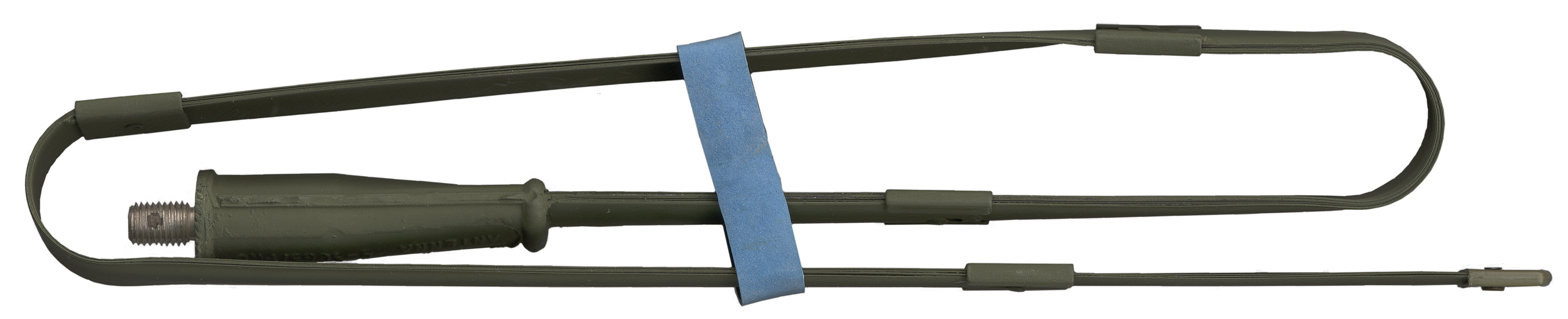
AS-3683() Short MP Antenna
 31" for
the tape whip part that has a male 5/16-24 thread like most
military antennas.
31" for
the tape whip part that has a male 5/16-24 thread like most
military antennas.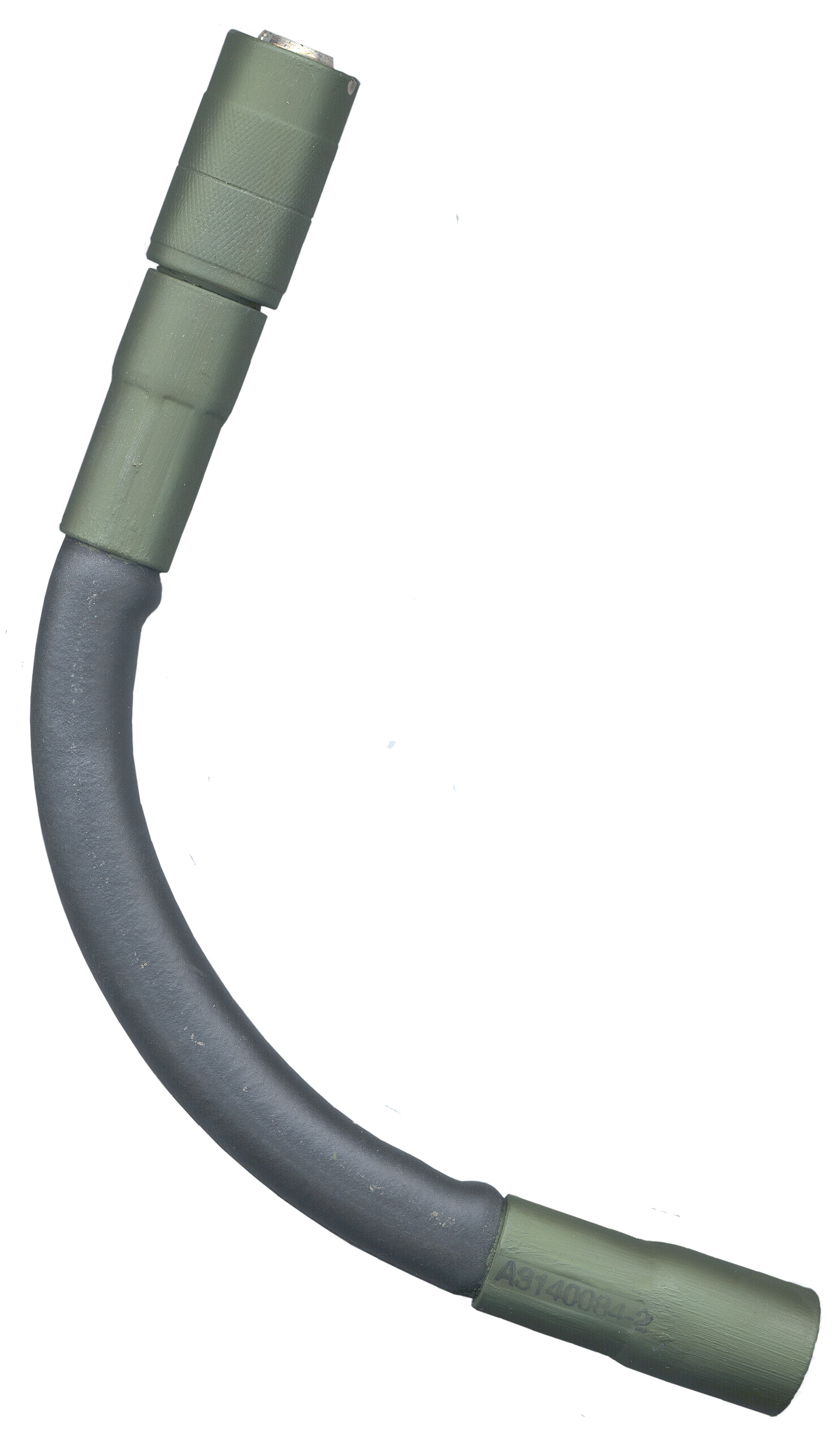 The SINCGARS radios have an
antenna switch that's similar to the one on the PRC-25 and PRC-77
radios. But instead of using panel space for both a
whip antenna and for a BNC connector for a 50 Ohm antenna
the SINCGARS radios combine these into one connector.
The SINCGARS radios have an
antenna switch that's similar to the one on the PRC-25 and PRC-77
radios. But instead of using panel space for both a
whip antenna and for a BNC connector for a 50 Ohm antenna
the SINCGARS radios combine these into one connector.When the A3140084-2 is installed the switch is NOT activated and when a standard BNC-m connector is installed the switch activates and the radio switches into 50 Ohm mode.
A3140084-2 shown at left.
TM 11-5820-890-20P-1 Figure 2
The A3140084-1 that was made by Unicor had a breakage problem. It has a visible spring at the base end.
AS-3916 Low Profile (SLPA) Ant Vehicular
AS-4266 Long MP Ant
Connects to radio using the 50 Ohm mode and has it's own matching circuit.
Replace the stock attaching sleeve with NSN 5935-01-468-5485 which is smaller in diameter allowing easier attachment. Use Loctite on the mounting screws. (Ref: PS mag Mar. 2001 580 pg 47). TM 11-5820-914-40P
AS-3900 Vehicular Ant
Built in protection up to 20,000 Volts A.C.
Lock washers needed both above and below each attachment bolt and on the ground strap for good electrical grounding. Ref Oct '96 PS mag pg 38.
Tip Cap NSN 5820-00-437-2352 will stay on without tape. Ref 1999 PS mag 564 pg 61
Do NOT paint the AS-3900 plastic antenna base. The paint will breakdown the plastic. Ref Feb '96 PS mag pg 35.
AS-3916
The collet (NSN 3460-01-435-8079) that holds the top antenna section is too long. File 1/16" off the bottom to fix it. (Ref: PS mag Sep 2002 598 pg 42).
Nut for connecting the antenna to the base NSN 1560-01-435-8079. Ref Jul '97 PS mag pg 61
OE-254 Dual Discone
Audio
H-250 Handset
Stepping out of a HMMWV and pulling the H-250 handset cord can break connections. A safety measure is to cut a 3 foot length of nylon cord and tie one end to the LS-671 and tie the other end around the handset just above the mike. This will limit the cord extension to a safe amount. Also a closeline made from the same cord and tied to the front canvas bow and hang the H-250 up and out of the way of damage. Ref July 995 PS mag 512 pg 44.
Another way to keep the H-250 handset up and out of harms way is to use Velcro to attach it the Mount. Ref Mar '95 PS mag 508 pg 42.
The problem is the clip designed for the H-250 puts it in the way of belt worn equipment (m-17, M-40) when the driver sits down.
HRCRD (Handheld Remote Control Radio Device) Handset C-12493/U
The main purpose is to allow the radio in a man pack configuration to be controlled by the operator without removing the pack to get access to the front panel. Can also be used with vehicle configurations for more convenient access to the most frequently used controls.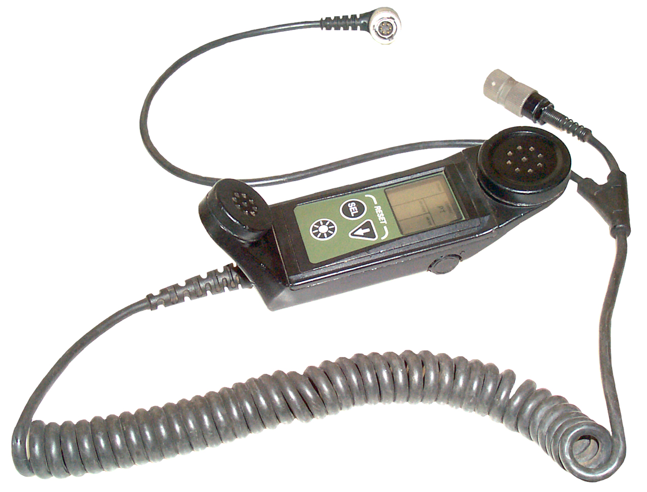 After setting front panel FCTN switch
to REM allows control of:
After setting front panel FCTN switch
to REM allows control of:RF Power: L, M, H, PA
Mode: SC, FH, FHM
COMSEC: PT, CT
Volume: analog
Back light on/off
This will work with the RT-1439 since it's related to the revision of the battery box and the only connection is the wire line remote control, the HRCRD uses the same audio signaling system as the CTRL-MON.
Manpack: connect cables to RT-AUDIO and CY-8523C
Vehicle: connect one cable to RT-AUDIO and for RT-1523E use AUX or with AM-7239 use J9 CTRL-MON.
This also means that a PC could do this function with software/hardware that emulated the tone functions.
There is no separate label, but molded into the plastic near where the cable leaves the handset is:
handheld Remote Control
C-12493/U
DAAB07-96-C-C008
NSN 5895-01-432-8370
and overstanped in white paint: 9806-C
The 6 pin AUDIO connector is marked: PCI-2298, OCS66
The 6 pin Radio Remote connector is marked PCI-106PM
Since the HRCRD can be used on J9 (CTRL-MON) then the signals are the same as for the C-11291 small Control Monitor. From TM 11-5820-890-30-4 Chapter 6:
I received an email that also had the Assembly number A3249865-1 for the HRCRD.
Manuals
Section V PLGR
Section VI HRCRD
TM 11-5820-890-20-2 Unit Maint Man
Chapter 10 HRCRD
TM 11-5820-890-10-7 Pocket Guide to SINCGARS ICOM ground radios
Section 8 HRCRD
TM 11-5820-890-20P-1 Figure 3
LS-671 Loudspeaker (A15)
 This is an amplified speaker
that interfaces using the standard VIC-1 cable (CX-13292).
This is an amplified speaker
that interfaces using the standard VIC-1 cable (CX-13292).The LS-671 can be connected to a handset (or microphone) and used for receive and transmit operations. It can turn the main DC power to the Mount & RT on and off. It can be located up to 100 feet from the RT providing a limited remote control capability. Note that if the LS-671 is left on and the Mount is turned off the LS-671 stays on and drains the vehicle battery. Best to leave the Mount turned on and just switch the speaker. (Ref: PS Mag April '04 Vol 616 pg 43)
Also be sure to fully unscrew the CX-13292 cable wing-nut BEFORE trying to remove the connector. Otherwise the struggle to get it off probably will break something inside the speaker. (Ref: PS mag 2003 621-44) Also do NOT twist the connector assembly for the same reason (PS mag Sep 2002 598 pg 43).
The Volume control on the LS-671 can be used to control the connected handset when in the normal position and when pulled out controls the speaker volume. Don't forget to pull it out. Ref Jan '97 PS mag pg 50.
J1 on the LS-671 is the standard VIC-1 18 terminal type connector and mates with the CX-13292 "VIC" cables. You should be able to use the LS-671 in any system that has the VIC-1 connector, like the VRC-12 series radios that use the MT-1029 mount which has the connector.
 When the LS-671 is connected using a
VRC-12 series radio (VIC-1) CX-4723
cable to the MT-6576 it works as a
speaker and audio feed to a handset connected to it, but
does not
allow keying the transmitter.
When the LS-671 is connected using a
VRC-12 series radio (VIC-1) CX-4723
cable to the MT-6576 it works as a
speaker and audio feed to a handset connected to it, but
does not
allow keying the transmitter.The reason is that the proper CX-13292 cable is not symmetrical and has the PTT line on different pin for the speaker end and the mount end, unlike the CX-4723 that is a symmetrical (1:1) cable. See TM 11-5820-890-20-01 Chapter 4 Cables, p4.2 CX-13292 Speaker Cable schematic.
There may be a need for the CX-13314 cable (MX-10862-J1(TEST) and the RT AUDIO/DATA connector with only 1 wire for PTT.
The combined LS-671 + CX-13292 may work with VRC-12 series mounts.
The On-Off switch on the LS-671 turns the speaker on or off, but not the mount. This is because the screwdriver switch that's between the radio and the mount was set to LOCAL, changing it to REM allows the LS-671 to control mount power, which is the recommended way to use the LS-671 so that both the speaker and mount are turned off (so as to not drain the vehicles battery when the radio is not in use).
 On the front of the LS-671 is a clip
for holding the H-250 handset.
On the front of the LS-671 is a clip
for holding the H-250 handset. On the back is a mounting bracket that allows the LS-671 to be removed by loosening the two large knurled screws. Why is this done? ans: the LS-166, LS-454 have wing nuts that allow you to remove them so that they can be used away from a vehicle, like in a tent.
The LS-671 can be connected to the Mount J3 or J4.
Manuals:
TB 11-5820-890-10-14 LS-671
TM 11-5820-890-30-4 Ch 16, FO-30 schematic
TM 11-5820-890-20P-1 Figure 119
LS671 block wiring diagram.pdf Submitted by rusty56@attglobal.net
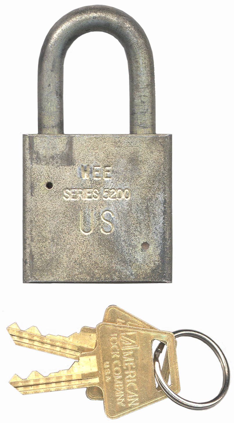
Series 5200 padlock
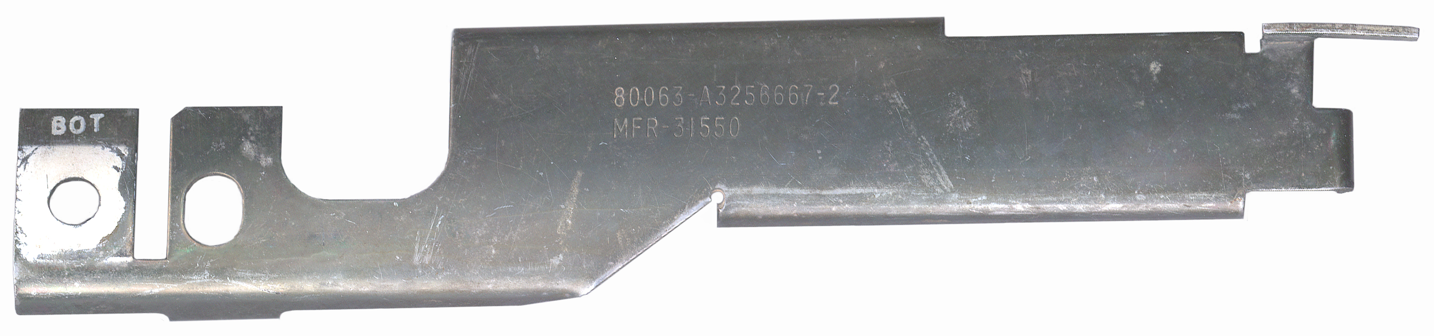 a bracket marked:
80063-A3256667-2
MFR-31550
 My local locksmith will
rekey the padlock for about $8 (he says it will take 10
minutes and the lock is worth about $20.
My local locksmith will
rekey the padlock for about $8 (he says it will take 10
minutes and the lock is worth about $20.This series of locks can have the 5 pin tumbler cylinder replaced for rekeying.
One locksmith in town could not rekey the padlock because I did not have a key. Note that when the hasp is open you can see a philips head screw down in one of the holes, which when unscrewed frees up the tumbler. The other locksmith in town had no problem grinding off the rivet and taking the lock apart, but when it came time to pick (using a shim) the tumbler in order to fit a key, he was delayed for some time since each pin has grooves that making using a shim very difficult. But in the end I now have the same lock and a coupe of keys.
The keys have a 5 digit number (one for each pin) that would allow duplicate keys to be ordered. Note that these numbers can be punched out of the key. If left in the key and someone gets them then the key is comprised.
In the Series 5200 padlock photo you can see that at the back of each key there's a "fish hook". This holds onto the key when the lock is open. The only way you can remove the key is after it's locked.
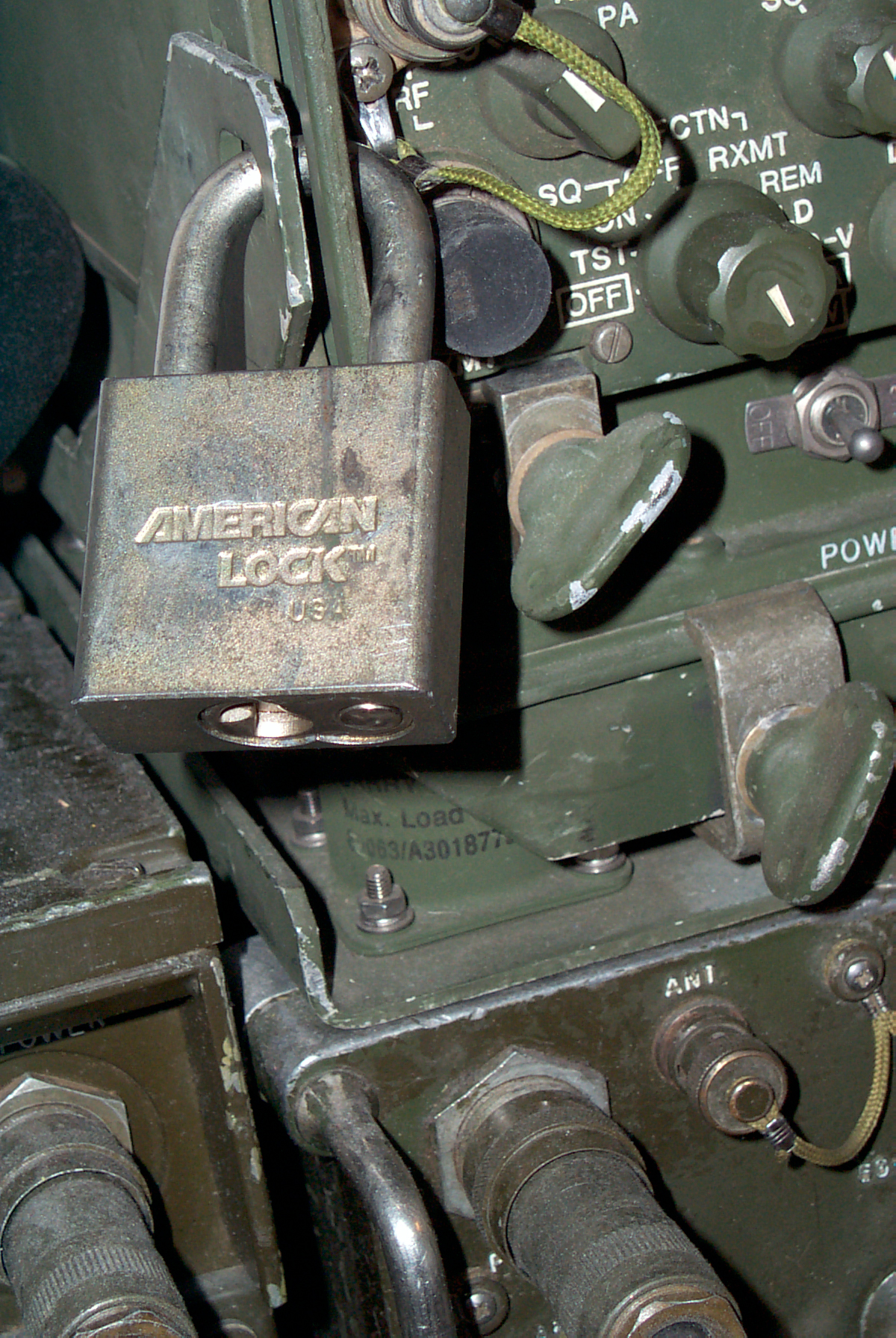
Lock installed between left bracket that's part of the MT-6576 and the left front panel grab handle on the RT-1439 trapping the MX-10862.
CX-13292 Speaker Cable

The military vehicle connector has a metal part added that puts a bend into the cable. Note that the CX-13292 cable has two different ends, one for the speaker and one for the radio and will not work if installed reversed.
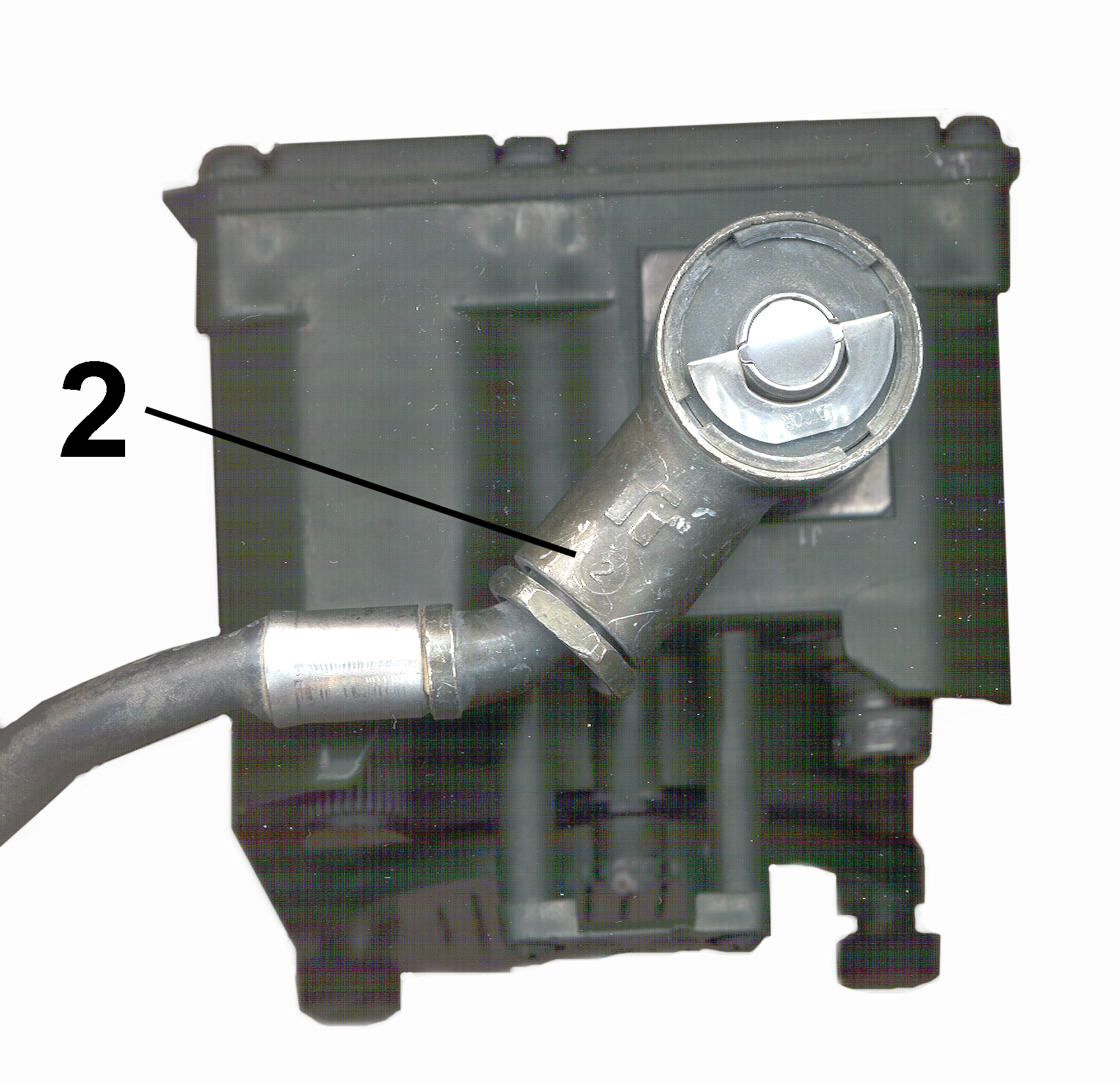
There are labels on the cable, but on the very used cable I got the sun has bleached out the labels so that they are very hard to read. But I notice that on the connector body of the SPEAKER metal connector there is a number 2 just above the nut and on the RADIO end there is a number 1.
LS-688/VRC, NSN
5965-01-382-3222 Manpack Speaker
LS-454
see: TB 11-5820-890-10-14 Fig 1
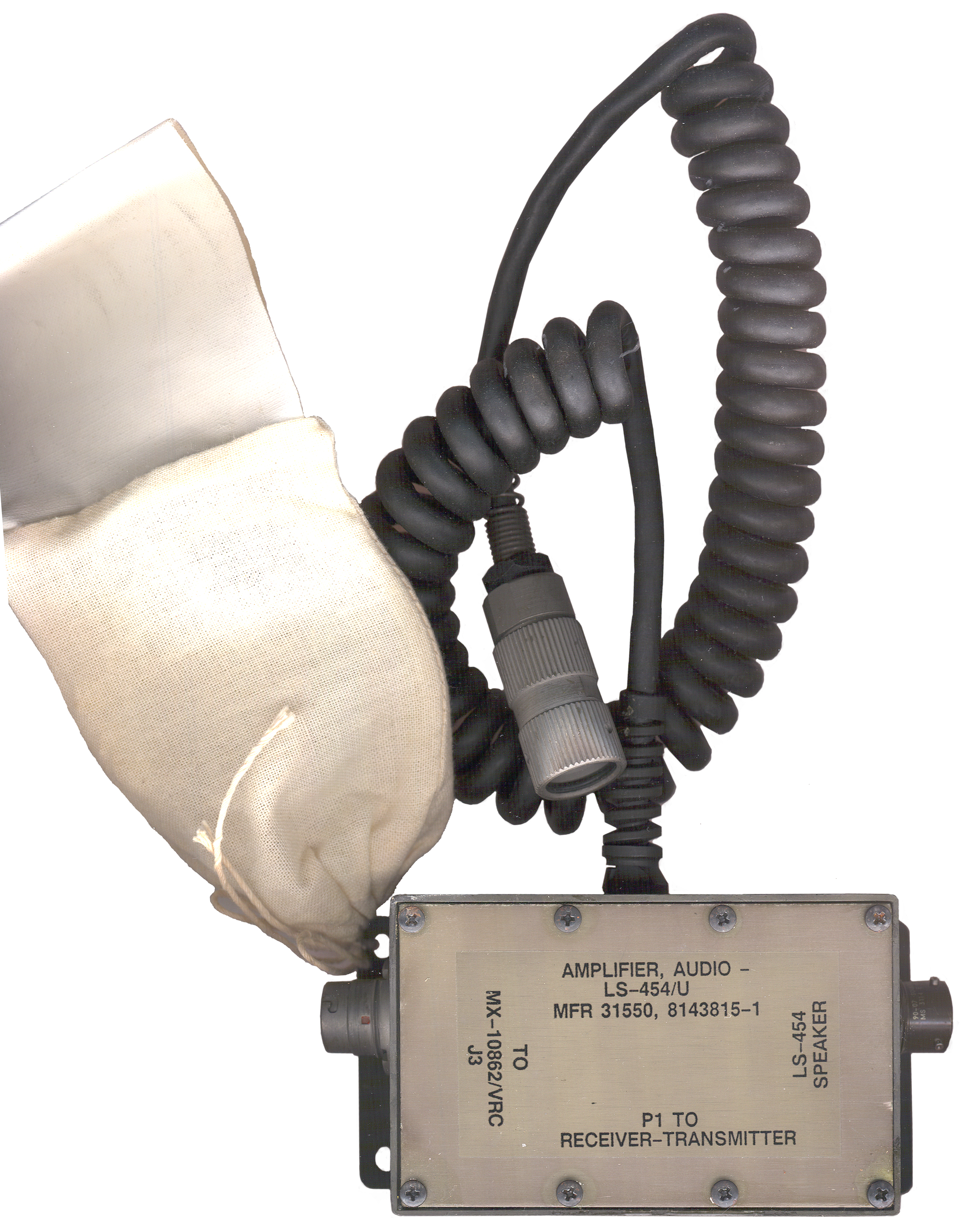
LS-454 Audio Amplifier
 It's
an
audio
amplifier
intended
for
use with SINCGARS radios, but there's some strange things
about it.
It's
an
audio
amplifier
intended
for
use with SINCGARS radios, but there's some strange things
about it.The label says:
Amplifier, Audio - LS-454/U, MFR 31550 (that's ITT), 8143815-1
with the ports labeled:
To MX-10862/VRC
LS-454 Speaker
P1 To Receiver-Transmitter
but there's no nomenclature and no NSN.
The 5 sheet manual that came with it is marked TB 11-5820-890-20-82 and is titled:
Installation and Unit Maintenance Instructions for Amplifier, Audio - LS-454/U to Permit Operation of Loudspeaker LS-454/U with Receiver-Transmitter, Radio RT-1439/VRC and Power Supply Adapter, Vehicular MX-10862/VRC
but there is already a manual with that TB number and it's titled:
Installation Instructions for Installation Kit Electronic Equipment MK-2616 /VRC to Permit Installation of Radio Sets AN/VRC-87/88/90 Series in a M915A2 Truck, Tractor (NSN 5895-01-361-7606) (EIC: N/A).
To use this amplifier a DC power cable CX-13290 is used between the amplifier and J3 on the back of the MX-10862. J3 is the connector used for either the HRCRD handset and/or the C-11291 Control-Monitor. But in this case the cable is only being used for 24 volt DC power and the 6-wire remote signals are not being used. The Amplifier has an attached coiled audio cable that needs to be connected to one of the AUDIO connectors on the front of the radio. The cable attached to the LS-454 is attached to a connector on the amplifier.
This may be a simpler way to get a loudspeaker then using the normal LS-671 but you don't get neither the remote power on-off capability not the remote handset capability with this amplifier. It probably was priced much below the LS-671.
M.C. design engineer. 8 May 2008 email
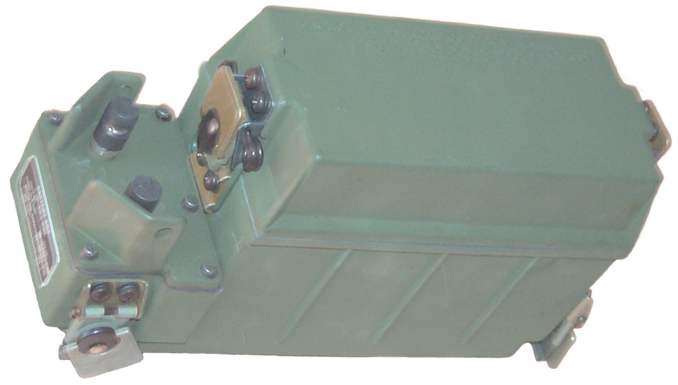
Battery Boxes & Trays
CY-8523() Battery Box
The battery box on the KY-57 and HYX-57 are designed very similar to the PRC-25 battery box with the vent although they hold the BA-559/U.
But the CY-8523() battery box was designed to withstand the explosion of a single "D" size LiSO2 cell in the BA-5590/U battery without allowing any stuff to be expelled. Note that a PRC-25 type vent can not get enough gas out fast enough to be of use. But it is not designed to contain an explosion of more than one cell like might happen if you tried to charge a BA-5590/U and the batteries internal protection diodes failed (like might happen after long term hot storage and when hot). This may have been related to why the Battery Tray has had the charging function deactivated, but that does not make sense since the Battery Tray uses pin 3 for charging and that pin is only active on rechargeable batteries (There's not even any metal in the pin 3 position on a BA-5590). If you know about this let me know.
CY-8523A
TM 11-5820-890-20P-1 Figure 12 Metal die cast body.
CY-8523B
TM 11-5820-890-20P-1 Figure 208 Plastic with a pair of telephone push terminals.
CY-8523C NSN 6160-01-424-8514
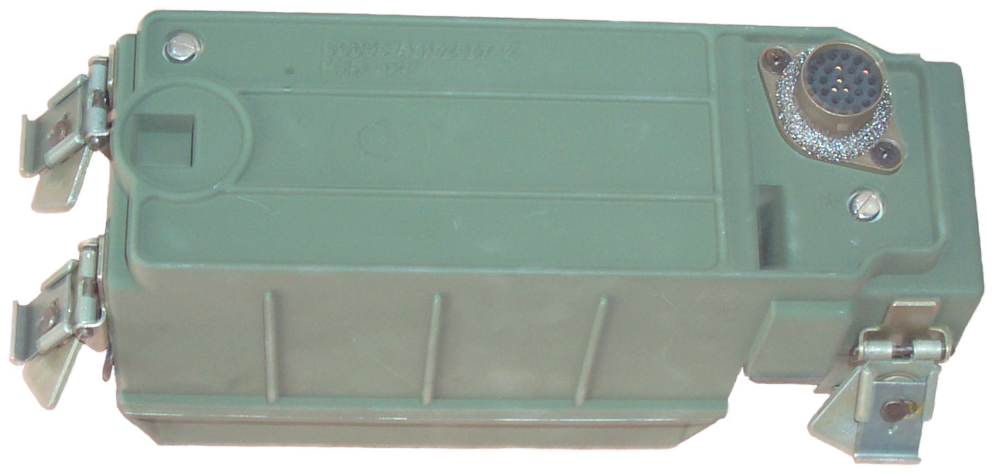
The CY-8523C replaces the two wire line terminals with a circular connector to support the HRCRD handset. This makes operating the radio while it's on your back much easier.
The HRCRD connector on the battery box is the same as the connector on the CY-8664 Battery Tray and the PP-8249 Battery Charger.
The CX-13290 cable mates to all of these. The cable plug is a MS3116F10-6P. This is also the same cable used with the C-11291 Control-Monitor.
TM 11-5820-890-20P-1 Figure 12A
CY-8664 Battery Tray (A12)
TM 11-5820-890-20P-1 Figure 13
PP-8249 Battery Charging Tray
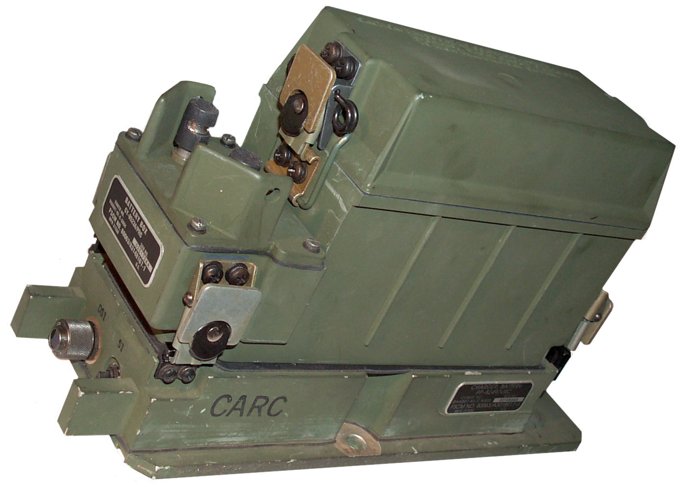 This is
identical to the CY-8664 with the exception that the
internal wire allowing battery charging has been
connected. Given new name so they will not be mixed
up.
This is
identical to the CY-8664 with the exception that the
internal wire allowing battery charging has been
connected. Given new name so they will not be mixed
up.Cabling Battery Box/Tray
Cables
External
| Nomen |
Description |
NSN & Manual |
Len |
1 |
2 |
3 |
| CG-3855* |
RF double shielded
|
TB
11-5820-890-20-90 |
BNC-m |
Rt Angle BNC-m | - |
|
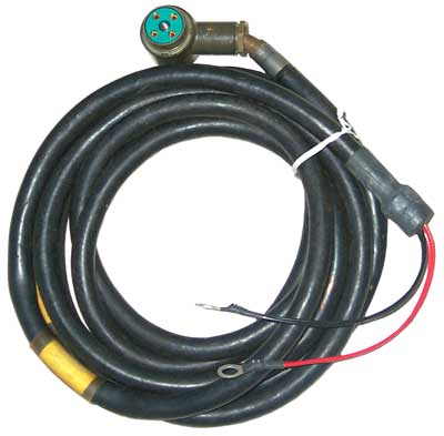
CG-3856 |
RF double shielded
|
5995-01-219-7025 | Rt Ang BNC-m | Rt Ang BNC-m | - |
|
| CX-4723* |
VIC-1 |
-18P |
-18P |
|||
CX-13072 |
HYX-57 to KY-57 |
-19 |
-26 |
- |
||
| CX-13089 |
MX7777 to 4-pin DC Power VIC-1 or sincgars? Fair Radio |
5995-01-062-8176 | 60" |
? |
MW20F(M)A00 | |
CX-13290*A3019154-1 |
Battery Tray or ChargerC-11291 C-M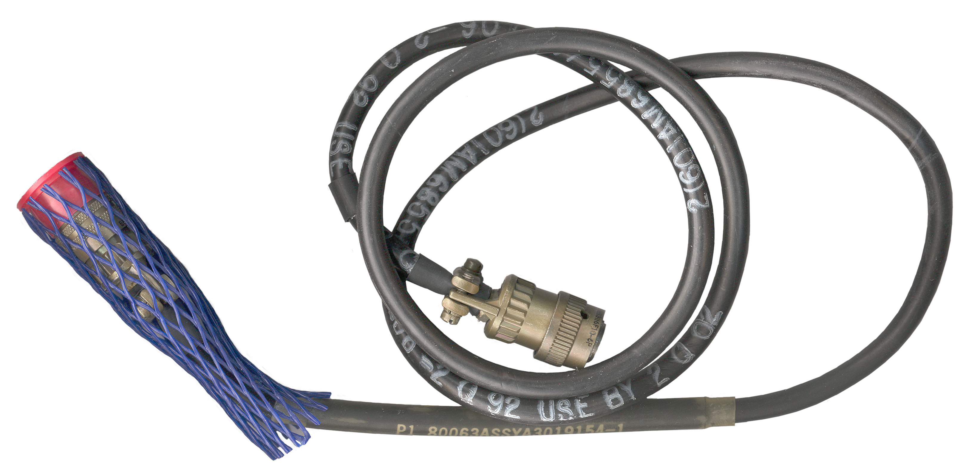 |
5995-01-306-8100 11-5820-890-20-2 |
48" |
MS3116F10-6P | MS3116F10-6P | - |
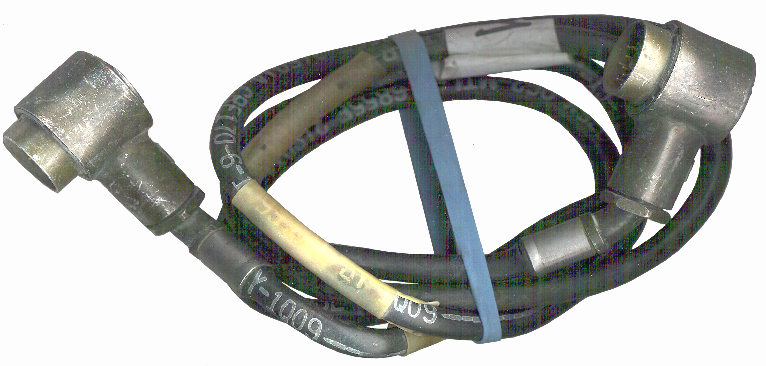
CX-13291* |
38" PA Control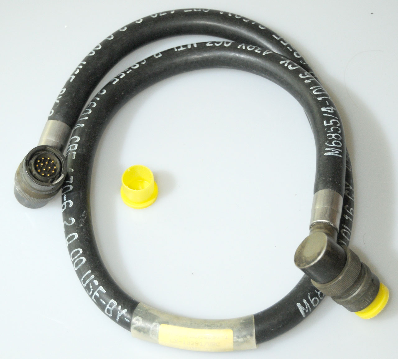 Power Connector Kit |
5995-01-222-4209 11-5820-890-20-1 |
-14P PCI U-317/U A3012759-1 |
-14P PCI U-317/U A3012759-1 |
- |
|
CX-13292 |
 Loudspeaker (Not VIC) PS mag Dec '98 pg 53 Different than CX-4723 |
schematic: TM 11-5820-890-1 Ch 4 Cables mentions: TB11-5820-890-10-14 11-5820-890-10-8 |
2' to 100' |
MW10M(M)-D17 N55181/7-03 Speaker end |
MW10M(M)-D17 N55181/7-03 Radio end |
- |
CX-13293 |
|
11-5820-890-30-5 11-5820-890-20P-1 Figure 3 |
4' |
-55P |
AUDIO |
-19S |
CX-13298 |
RXMT |
11-5820-890-20-1P4.2 |
RtAng
AUDIO |
RtAng AUDIO | - |
|
CX-13300* |
VIC RXMT |
MW10M(M)-011? | MW10M(M)-011? | - |
||
CX-13301 |
M551 DC Power |
MW20M(M)A00 |
MW20F(M)A00 |
- |
||
CX-13302 |
 DC Power A is shell and black ground, B is red Positive, C & D no connection |
2
red & 2 blk wires |
MW20F(M)A00 | - |
||
CX-13303* |
DC PowerDaisy Chain |
5995-01-219-4697 11-5820-892-20-1 |
MW20M(M)A00 | MW20F(M)A00 | - | |
CX-13304 |
DC PowerDaisy Chain |
MW20M(M)A00 | MW20F(M)A00 | - |
||
CX-13305 |
DC Power |
4 Wires | MW20F(M)A00 | - |
||
CX-13306* |
DC PowerIntercom |
-3P |
MW20F(M)A00 | - |
||
CX-13307 |
Digital Message Device
(DMD) |
A3014054 |
- |
|||
CX-13308 |
M23 Motor Ballistic
Computer PSG-2A PSG-5 Speaker Extension |
TB
11-5820-890-10-13 TB 11-5820-890-10-9 TB 11-5820-890-10-10 |
UG-77 | AUDIO | - | |
CX-13310 |
HYX-57 to SINCGARS |
TB
11-5820-890-10-3 |
-26P |
AUDIO |
- |
|
CX-13311 |
MST-20 |
-14P |
AUDIO |
AUDIO |
||
CX-13312 |
PSC-3 (RT-1402)VIC Interface |
-14P |
AUDIO | AUDIO | ||
| CX-13313* |
VIC-1 PYTHON |
11-5820-890-30-5 |
MW10M(M)-011? | MW10F(M)-011? | - |
|
CX-13314 |
PTT Cable (PTT for LS-671)
|
6130-01-284-4195 11-5820-890-20-2 p5.4 |
AUDIO | - |
||
CX-13402 |
TacFire |
AUDIO | AUDIO | - |
||
CX-13404 |
KY-90 |
TB
11-5820-890-10-7 |
AUDIO |
-14P |
KY-90-? |
|
CX-13417 |
VIC Splitter Dual Speaker used on SR/LR or LR/LR |
NSN
5995-01-348-2264 |
-18P |
-18S |
-18S |
|
| CX-13448/ 1 GYK-37 |
Light Weight Computer + Tactical Communications Interface Module to VRC-12 or SINCGARS radio |
FM 6-60 MLRS |
AUDIO (RADIO) |
AUDIO (TCIM) |
- |
|
CX-13450 |
DC Power |
4 Wires | MW20F(M)A00 | |||
| CX-13465 |
Digital Adapter |
AUDIO | AUDIO | |||
| CX-13467 |
AN/CYZ-10 to SINCGARS Fill
|
5995-01-379-9689 | DB- |
U-229
type |
||
CX-13509 |
DC Power |
MW20F(M)A00 | ||||
CX-13528 |
SNAP |
|||||
W-2 |
RF |
|||||
W-4 |
Audio/Data/Fill |
5995-01-310-0335 | AUDIO | AUDIO | ||
| AN-PSN-11 PLGR GPS Time
Fill |
6150-01-375-8666 |
AUDIO | AUDIO | |||
| CV-4228 |
PC/Fill SINCGARS |
7050-01-355-9729 | 4' |

Note 1 - The CX-13488 is wired 1:1 which is consistent with being able to connect to either a VRC-12 series radio or a SINCGARS radio. That's to say the "data" carried by this cable probably is in the form of audio tones, not digital bits. I think the TCIM is being replaced with routers for the Tactical Internet. This cable could be used as an extension cable for any AUDIO type application, except both ends are plugs, so it's probably only good for connecting two boxes with an AUDIO cable.
Cable Manuals
TM 11-5820-890-20-1 Chapter 4 has cable schematics
TM 11-5820-890-20-3
Section 4 has cable drawings
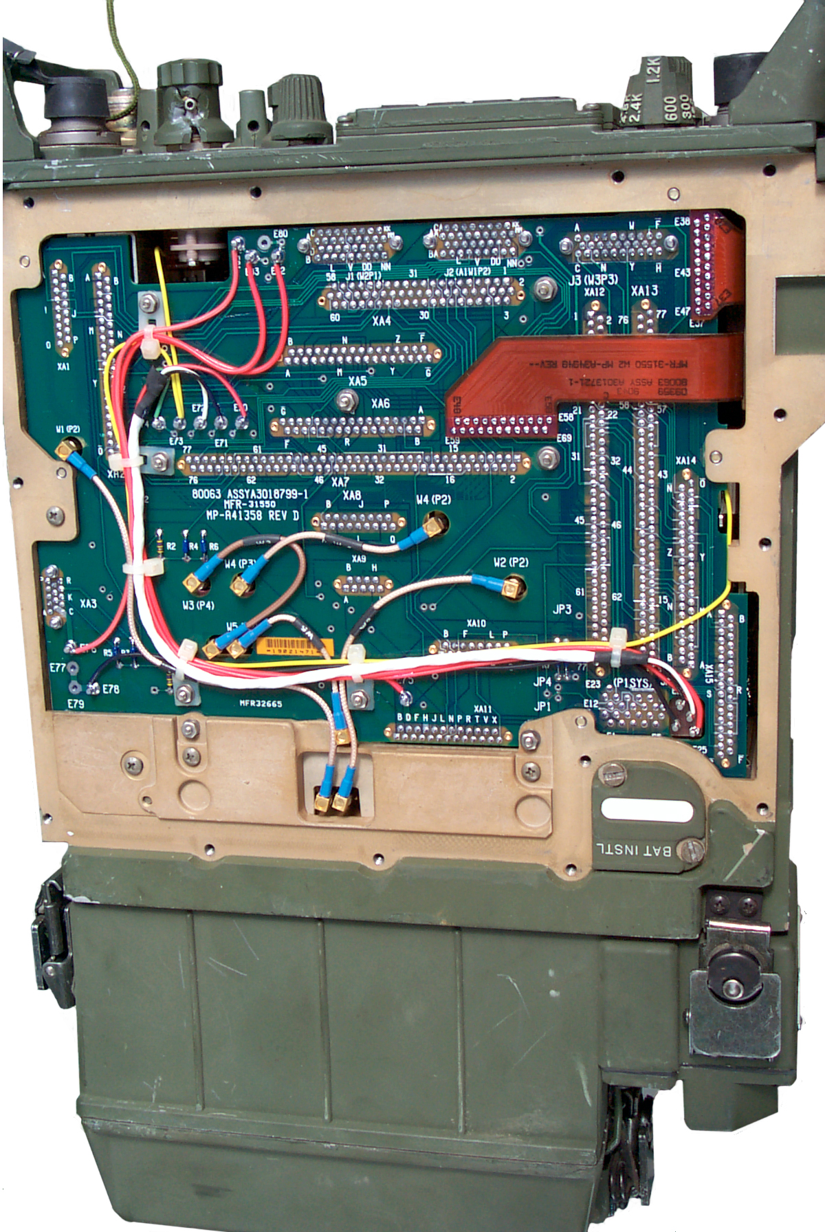
Internal Cabling
Based on the RT-1439 the coax cables are carrying the RF input frequency range and the Rx and Tx LO frequencies which are no more than 20 MHz higher than the basic RF range (30 to 88 MHz) and also a 12.5 MHz IF signal.
It's reasonable to expect that the other versions would use coax for signals in these frequency ranges (but maybe putting the IF on a trace), but for sure keeping the VHF signals on coax. But, so far, it's not clear what the different version number modules are doing. For example the first module that connects to the front panel antenna jack must contain the antenna matching circuit. In the case of the 1439 this module then has a coax to the module that contains both the transmit exciter power amplifier and the receiver low pass filter. The 1439 synthesizer has two outputs, one to drive the receiving mixer and the other to drive the exciter power amplifier.
Manuals:
RT-1523D = TM 11-5820-890-20P-1 Fig 205 It may be that the
The 1439 is very similar to the 1523 in most respects, it just has the added ICOM module. These have the modules both front to back and side to side.
The coax paths in the RT-1523A (GDLS) are completely different from the RT-1523 (ITT). At first glance these appear similar since all the modules are lined up like books and are numbered left to right. But in the RT-1523A there are 8 boxed modules but in the RT1523D only 6 boxed modules.
Carry Case, Manpack
Mounts
If there's an LS-671 connected to a mount then use the switch on the LS-671 as the main radio power switch. But if there's no LS-671 then the mount circuit breaker needs to be turned off, not just the RT FCTN switch. If the FCTN switch is turned fully CCW but CB1 on the mount is left on the mount will drain the vehicle battery. Ref Sep '96 PS mag pg 37.
MT-6352 Dual Radio PS/A Mount (A13)
 |
 |
| Left rear has oblong connector that mates with rear of AM-7239 Dual Radio Power Supply/Adapter. Note there are two sets of clamps on the front. The outer set holds the AM-7239 and the inner set of clamps holds the RT on the lower shelf. | Do
not understand why the bottom of the Mount is
so wide. Maybe it's on a mounting shelf? |
Very similar to the MT-1029 used with the AM-2060 and PRC-25 or PRC-77.
Connectors:
| Function |
MT-1029 | MT-6352 |
| DC
in |
J21 |
J1 |
| DC
Out |
J23 |
J2 |
| VIC
or TSEC |
J22 |
J3 |
| VIC
or TSEC |
n.a. |
J4 |
| to
Amp-PS |
J24 |
J5 |
TM 11-5820-890-20P-1 Figure 109, 110, 111, 206
Note the four corner mounting holes accept a 5/6-32x1" mounting bolt. These holes are in the same location for the MT-1029, MT-6234 and this MT-6352.
An approximate hole pattern is:
Front mounting holes are 13.375" apart left to right.
Left rear hole is 8.09375" behind left front hole.
Right Rear hole is 10.9375" behind right front hole.
If you know the design dimensions please let me know.
MT-6353 RF Amp Mount
This mount holds the AM-7238 RF Amplifier. Fed using a CX-13291 Cable from either a single radio Power Supply/Adapter MX-10862-J5 or a Dual Radio Power Supply/Adapter AM-7239-J11. On-Off Breaker/Switch on front and dimable pilot lamp. On the bottom rear are three connectors: DC In, DC Out and 14 pin control. The same 14 pin control connector is used to mate with the AM-7238 Amplifier.There is an electronics box as part of the mount and it's job is to generate the 200 Volts needed by the amplifier PIN diodes for band switching.
 |
 |
| MT-6353
Top w/o Amp |
MT-6353
Bottom
Connectors |
Has it's own 4 pin vehicle DC input and 4 socket DC output connectors and so would be connected downstream from the RT. Note that no RF goes to or from the mount.
| Jack |
#
pins
|
Function |
| J1 |
4 |
Vehicle
DC In |
| J2 |
4 |
Vehicle
DC Out |
| J3 |
14* |
CX-13291
to PS/A |
| J4 |
14* |
Direct
Connect
to RF Amp |
I sell a Power Connector Kit that includes this connector, 2 would be required to make the CX-13291 PA control cable described in TM 11-5820-890-20-1. It should be made from 9 conductor shielded cable.
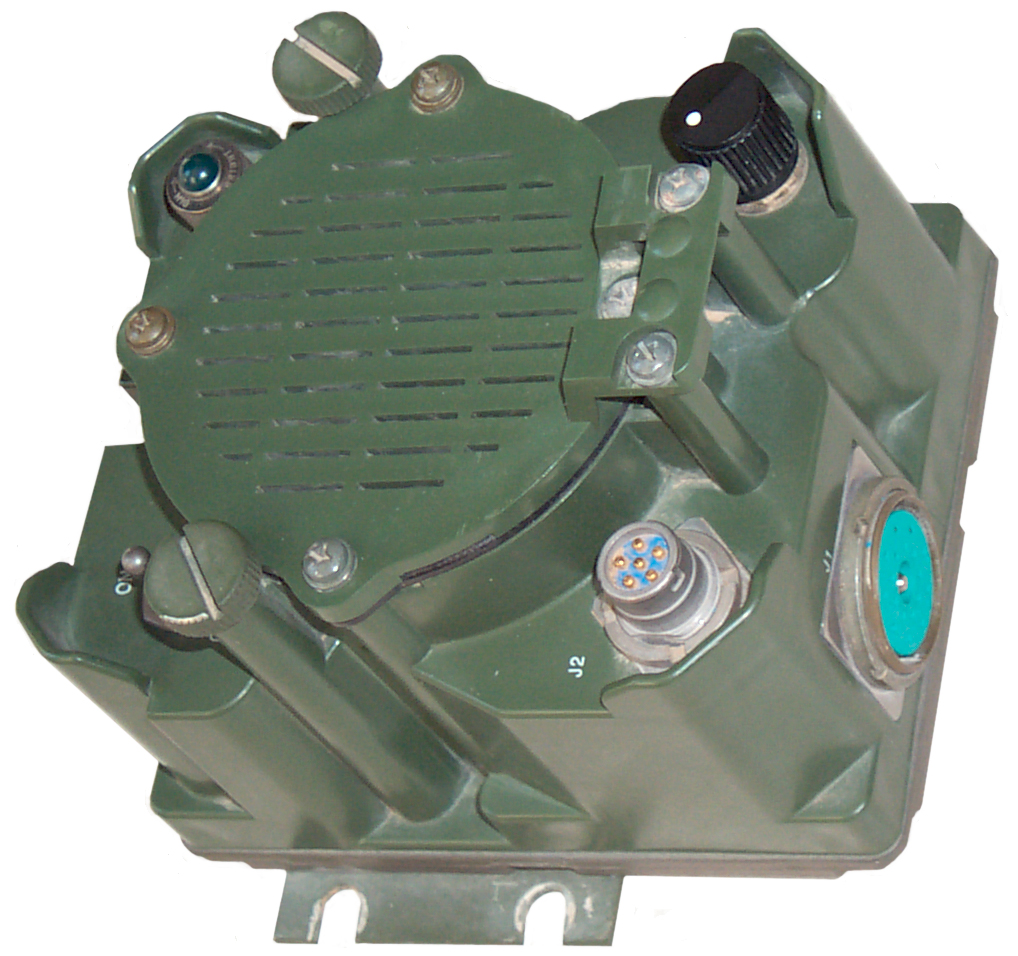
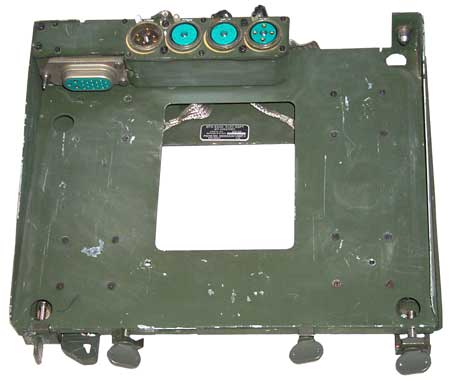
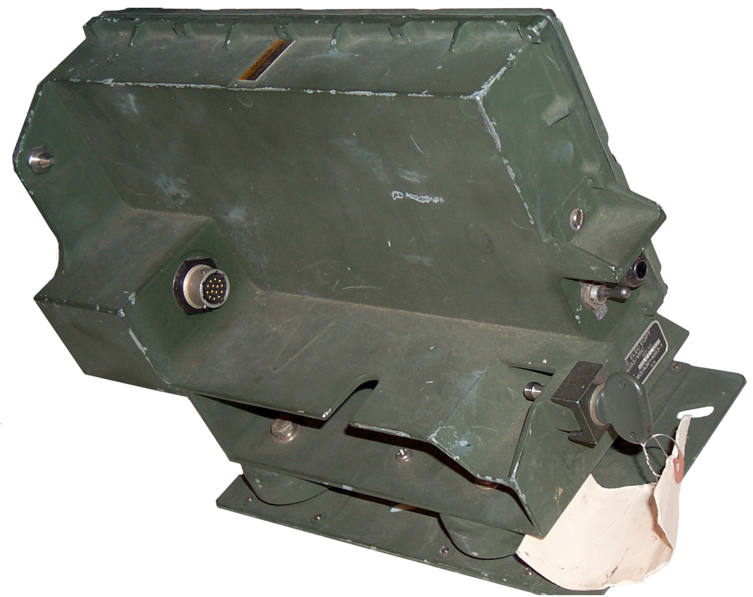
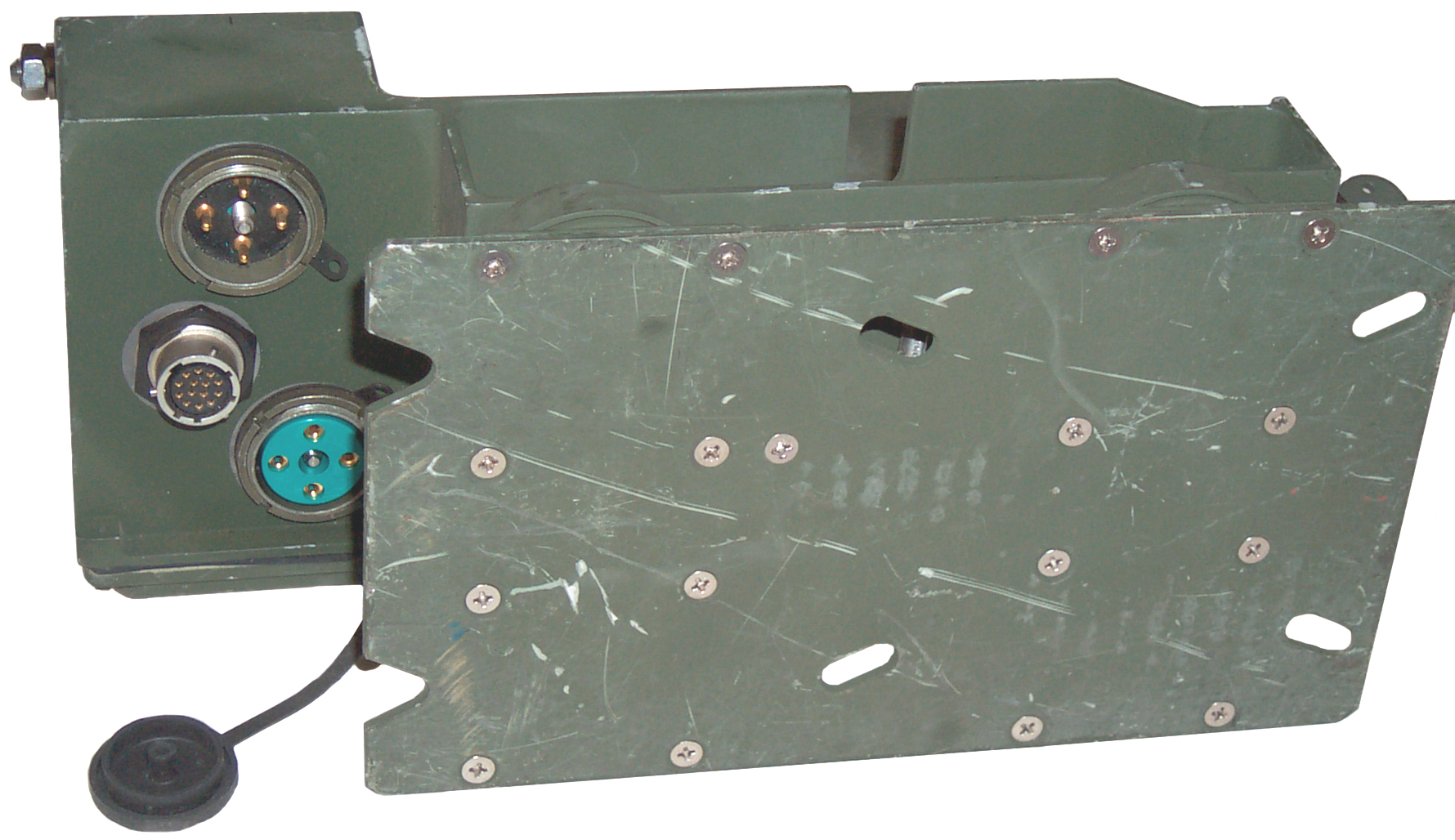
MT-6576 Single Radio PS/A Mount (manual says A9 ? marked A4)
 Used with the MX-10862 Single Radio
Mount (SRM) Power supply Adapter PS/A.
Used with the MX-10862 Single Radio
Mount (SRM) Power supply Adapter PS/A.Looks very similar to the MT-6352, why is it different?
Ans: It's narrower since there is no need for mounting an AM-7238 RF Amp.
This mount is an optional component of the VRC-87 (SR), VRC-88 (SR-D) or VRC-90 (LR) vehicular radio systems.
The metal plate on the left side allows a padlock to attach the radio directly to the mount and since the guide pins and rear connectors are engaged also traps the MX-10862 between the radio and mount.
What Goes Wrong
As delivered there were some problems. The DC power input connector J1 had a pin B (+27V) broken off and someone had started to make a repair but quit after removing all the wires from the connector and not marking them. It was easy to figure out that all the red wires went to B, Black to A, Brown to C and white to D. Note there are only two ways the connector can be installed in the box and it's best done with the alignment ridge toward the front of the mount to allow easy cable connection. But even then the CX-4720 connector needed to be turned one notch.One the the thumbscrews on the front had been hit hard damaging it's threads and the threads in the mount. The M8 threads are 8 mm x 1.25 mm and a tap for the mount and a die for the thumbscrew chased the threads clean. The mount hole was at an angle and after installing the thumbscrew all the way in a small hammer blow got the threads aligned.
The (-) screws go all the way through the box and hold it to the mount. The (+) screws hold the lid onto the box.
Adapters
AM-7239() Dual Radio Power Supply/Adapter (A5)
Interpretability
The 7239, 7239A and 7239B all work fully with the RT-1439.The 7239C, 7239D and 7239E support data packets which the RT-1439 & RT-1523 do not support. A RT-1523 C/D/E is needed for this. The RT-1523A will not mechanically fit. They are probably the ones that also have the GPS connector.
Locking bar NSN 5340-01-352-3053 and A-200 padlock NSN 5340-00-158-3807 with 5/16" hardened steel shank. Ref 1995 PS mag 514 pg 46.
The Dial Light can be mechanically dimmed all the way to being blacked out. Then it's easy to forget to turn off the Mount circuit breaker thus draining the vehicle battery. (Ref : PS mag for Dec '98 pg 52)
| Jack |
Function |
| J1 |
Direct
to RF Amp |
| J2 |
Audio/Data |
| J3 |
Audio/Data |
| J4 |
Data |
| J5 |
Data |
| J6 |
Speaker |
| J7 |
RT-B
(top) |
| J8 |
RT-A
(bottom) |
| J9 |
CX-13290
to Ctrl-Mon |
| J10 |
CX-13179
to CP-1380 (SNAP) |
| J11 |
CX-13291
to RF Amp B |
| E1/2/A/B |
Wireline
remote
control |
| P1 |
Interface
to Mount |
 |
 |
| Tray
Side |
Mount
Side |
| Version |
NSN |
Manual |
| AM-7239 | 5895-01-188-8819 |
TM 11-5820-890-20P-1 Figure 86 |
| AM-7239A |
5895-01-323-6265 |
TM 11-5820-890-20P-1 |
| AM-7239B | 5895-01-334-3164 | TM 11-5820-890-20P-1 Figure 146, 151, 153 |
| AM-7239C | 5895-01-421-0093 | TM 11-5820-890-20P-1 Figure 211, 212, 213 |
| AM-7239D | 5895-01-422-8781 | TM 11-5820-890-20P-1 Figure 214, 214 |
| AM-7239E | 5895-01-444-1218 | TM 11-5820-890-20P-1 |
Note that the radio in the lower shelf is the Long Range radio that uses the AM-7238 RF power amp.
MX-10862 Single Radio Power Supply/Adapter Tray (A8)
10 7/8" wide x 12"+/- Deep x 5 1/4" high.
TM 11-5820-890-20-2 Chapter 5
The MT-6576 Single Radio Mount draws 0.32 amps with only the MX-10862 installed and no current draw when the MX-10862 is off.
 |
 |
| Tray
Side
J2 (RT) Power sw, Lamp, wire line terminals, J1 Test Con Add-on left thumb screw has big lock hole |
Mount
Side J3 (CTRL-MON), J5 (RF Amp), J4 (Batt), P1 (Mount) |
 |
 |
| RT-1439
+ MX-10862 Front
Qtr View Stock left & right thumb screws have 2 small safety wire holes |
RT-1439 + MX-10862 Rear Qtr View |
| Jack |
# pins |
Function |
| J5 |
14 |
CX-13291
to RF Pwr Amp |
| J2 |
28 |
to
RT |
| J1 |
14 |
Test
or PTT* |
| J3 |
6 |
CX-13290
to Ctrl-Mon |
| J4 |
6 |
CX-13290
to Battery Tray |
| P1 |
Interface
to Mount |
|
| E1
& E2 |
1+1 |
wire
line remote |
* J1 is used for testing or to accept an external PTT signal by means of a CX-13314 to an LS-671.
Both 14 pin jacks are the same as the POWER connector on the PRC-25 and PRC-77 as the POWER connector.
Note that J5 is to support an external RF Amp, and is an optional configuration of the VRC-90.
This Power Supply/Adapter has a BATT connector for use with the CY-8664 Battery Tray or the PP-8249 Battery Charging Tray to provide DC prime power even when the vehicle DC power sags(but not when it's zero), like in an armored vehicle when the hydraulic pumps are working hard. But the AM-7239 does not have the BATT connector, so is it not used in armored vehicles.
I wonder if having the external battery takes a load off the radio's internal HUB.
AM-7238() RF Amp (A6)
The amplifier has it's frequency coverage split into three bands as described in TM 11-5820-890-30-4 Paragraph 5-3 on pdf page 577.
| Filter/Band |
Frequency MHz |
| A |
30 43 |
| B |
43 - 61.5 |
| C |
61.5 - 88 |
Note this is a different band plan than that used on the PRC-25 and PRC-77 where the band split is: 30 - 52 and 53 - 75 MHz.
So even if you could jury rig a band signal out of the PRC-25 or PRC-77 it would not match the band plan of the AM-7238 amplifier.
So the only way you could use the AM-7238 with the PRC-25 or PRC-77 would be to use a manual band switch to control the amp which would be set prior to keying the radio. If the manual switch was set improperly it might let some smoke out of either the amplifier and/or radio. So this is probably not a good idea. Another option that would work would be to build a "smart interface" that would use a counter to determine the frequency coming out of the radio and select the appropriate amp band. But even this would need some safety precautions to prevent a frequency change going unnoticed.
 |
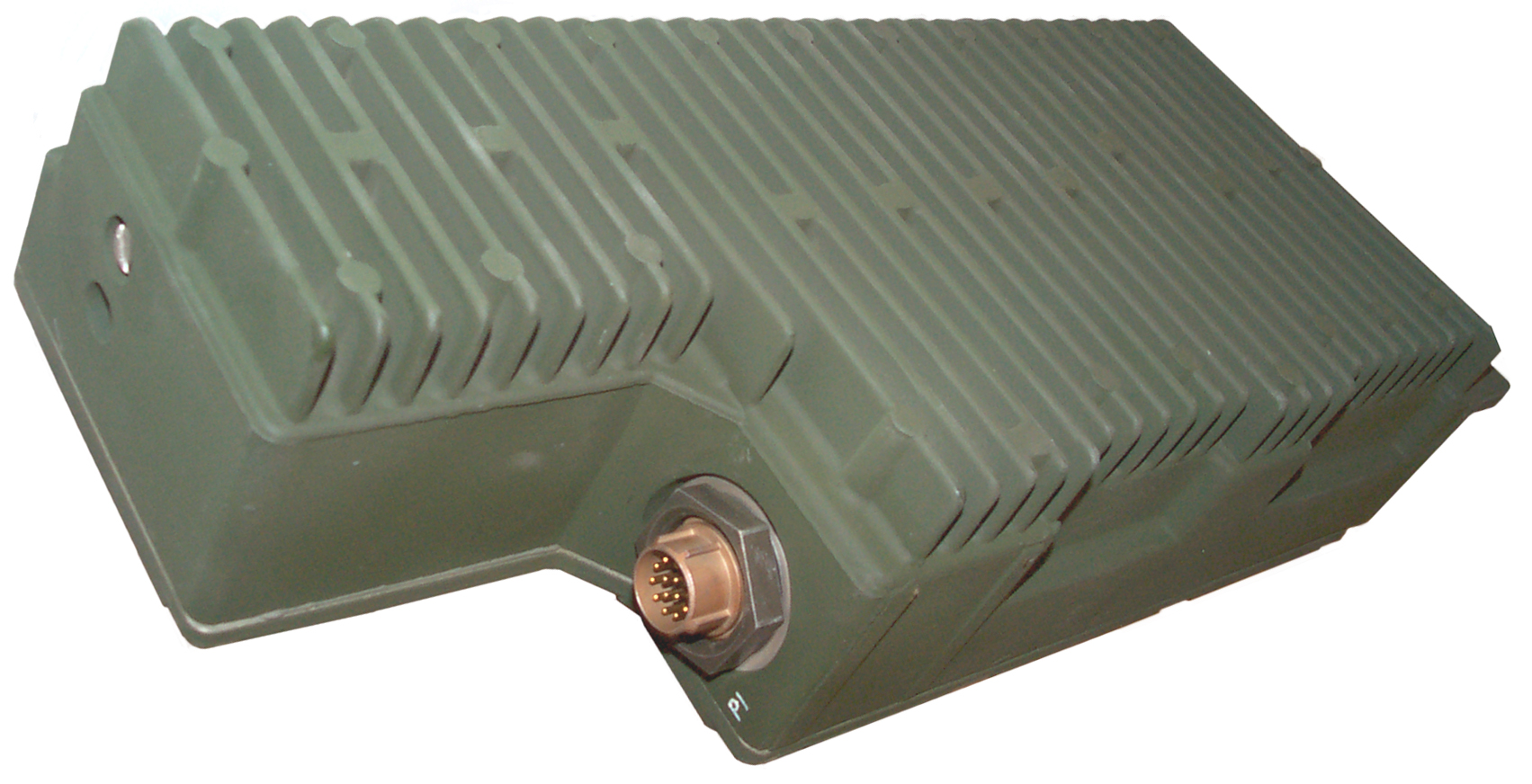 |
| BNC
RF Connectors end |
P1
14-pin connector end |
Remotes
There are a couple of hardware interface methods allowing remote operation. 6-Wire non secure and 2-Wire secure.
6-Wire
There is the non secure 6-wire protocol like used with the HRCRD, C-11291 Control-Monitor.
HRCRD
Non Secure. 6-wire protocol. See above.
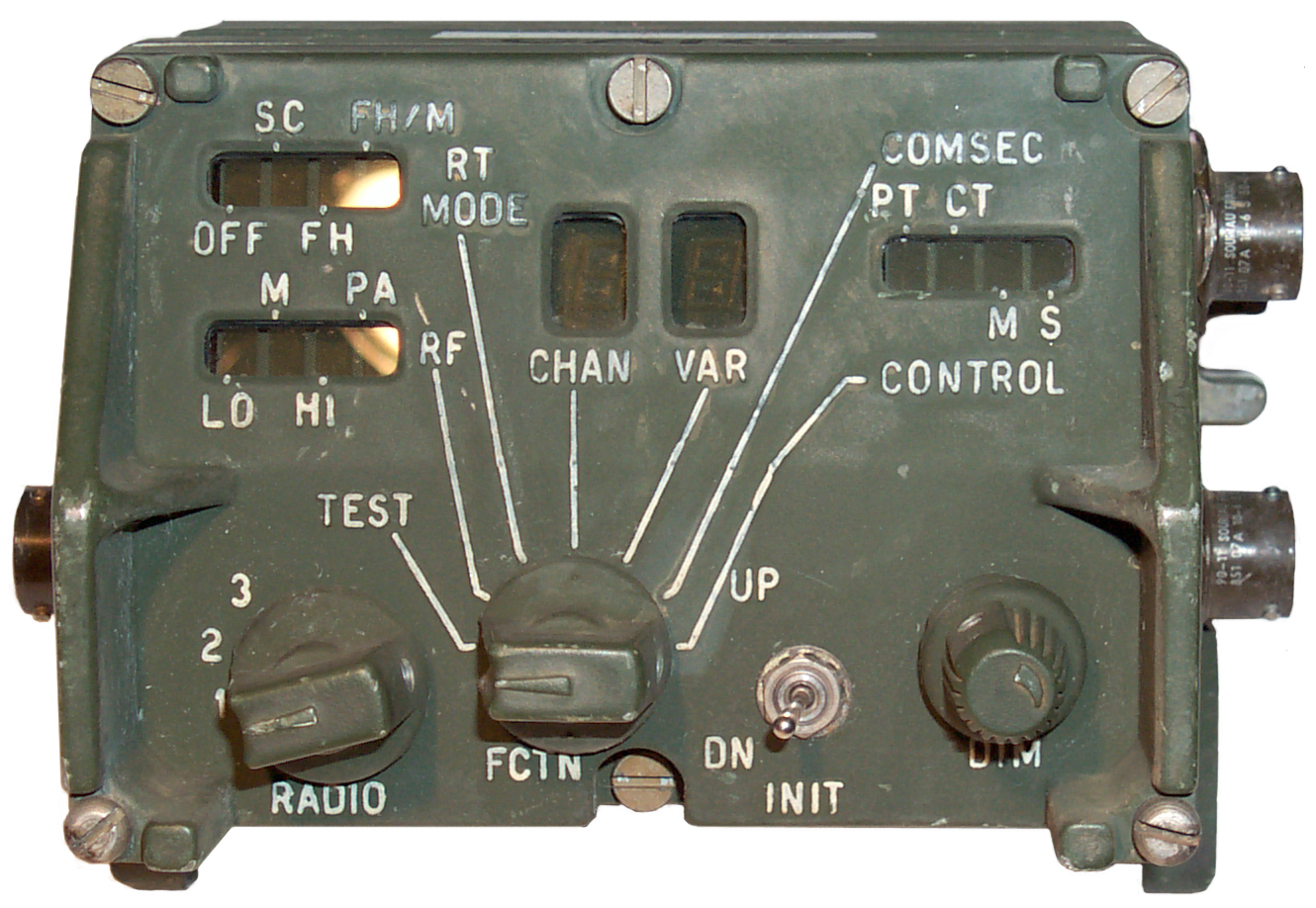
C-11291 Control-Monitor (C-M) (A7)
6-wire protocol has the same functions as the HRCRD plus it can turn the RT off.
This is the small non secure remote that works using the same in band audio protocol as the HRCRD. Typically used in vehicular installations. Two are used inside the M60 tank.
The upper right display has two functions in one window. COMSEC: PT or CT and CONTROL Main or Standby.
J3 is used to connect a second C-M and has a 650 Hz data stream that's different from the 2880 Hz data stream used for radio coms. This means that only 2 C-M can be connected in tandem, they can not be daisy chained. Although the name for J3-E is C-M out and for J3-F is C-M In. on the functional schematic, they probably should be called J3-E data and J3-F Clock, or some other names that don't imply a cross connect cable is needed since a standard CX-13290 cable can be used between the two J3 connectors of a pair of C-Ms. Ref: TB 11-5820-20-49 Fig 5-8(1) Cabling M60A1/A3 with VRC-89/91/92.
The CX-13290 cable is also used with the CY-8664 Battery Tray and the PP-8249 Battery Charger. In TM 11-5820-30-5 FO-21 Battery Tray Schematic dia it shows the CX-13290 with pins A and F wired straight through and pins D & E crosses (i.e. D-E and E-D) and B & C are crossed (i.e. B-C, C-B) But those are not the correct pins to cross to get E & F crossed which is implied by the names of the C-11291 pins??? It may be that C-M Out and C-M in are on pins D&E which are crossed in the cable and the C-M presence is sensed on C or F?
Note the C-M is the same size as and has mounting provisions to attach to a VIC-1 control box also has rear ears so can be mounted on a wall.
Note the display is red to match the display color of the RT-1439. (thanks Kurt).
6 pin connectors:
Pin
J1
VAA J9
Radio 1 & 2
J2
radio 3
J3
2nd C-M-J3
A
Gnd
Gnd
Gnd
B
RT1a
RT3a
27.5 vdc in/out
C
RT1b
RT3b
Gnd
D
RT2a
C-M Pres
E
RT2b
C-M Out
F
27.5vdc in
C-M In
TM 11-5820-890-20P-1 Figure 4
TM 11-5820-890-10-1 Chapter 4 sec II operation2-Wire
The 2-Wire protocol is secure when the radio is keyed.
CY-8523A or CY-8523B Battery Box
These have regular telephone type push down terminals (E1 & E2) for remote operation.
Note the E1 & E2 2-Wire terminals on the battery box.
CY-8523C Battery Box
This battery box has a 6-pin circular connector for the HRCRD remote control microphone, but that can be used by the above 6-wire remote controls or the below 2-Wire adapter that interfaces between the 6-wire and 2-wire protocols.
AM-7239() Dual Radio Power Supply - Adapter
These have the E1 & E2 remote terminals as well as J9 for a 6-Wire Control-Monitor.
MX-10862 Single Radio Power Supply/Adapter Tray
Has both the E1 & E2 2-wire terminals as well as J3 for a 6-Wire Control-Monitor.
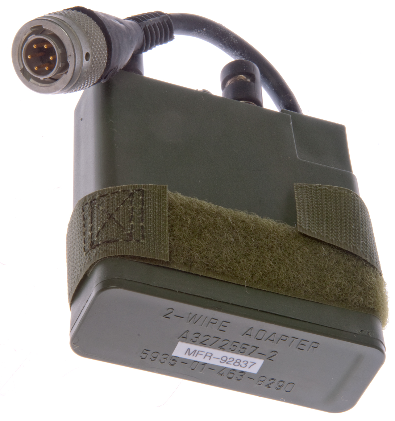
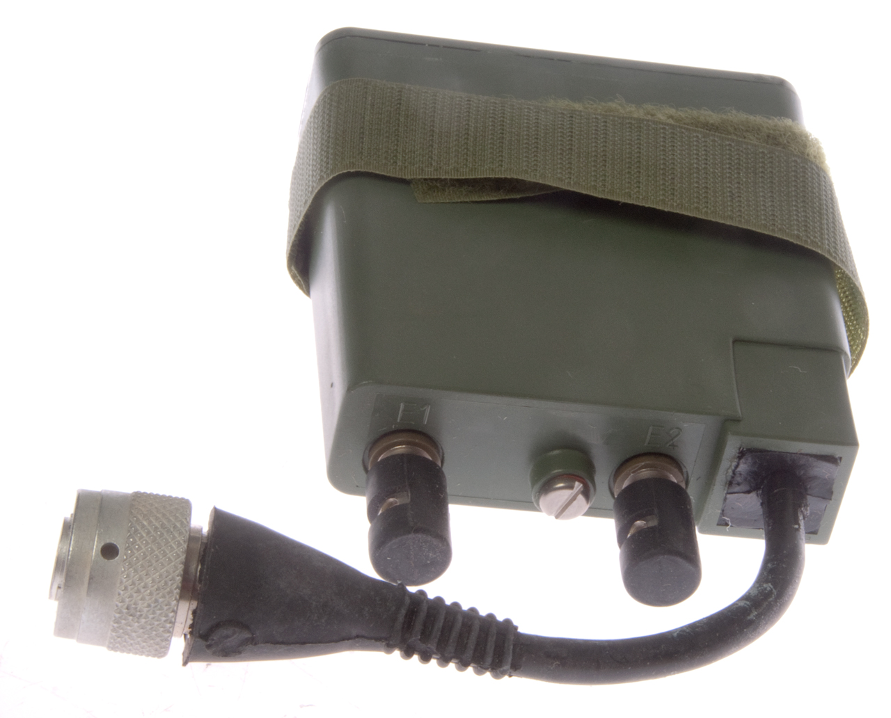
2-Wire Adapter
This is an adapter that goes between the 6-wire remote protocol and the 2-wire remote protocol.
The main use probably is by connecting to J6 on the new 1/2 size SINCGARS radios (RT-1523E & RT-1523F) and WD-1 field wire.
But it also could be used
These showed up on eBay atticstocksurplus August 2016 new in the sealed bag.
The bag is marked:
NSN: 5935-01-463-8290
CAGE PRIME 92837
SINCGARS 2-Wire Adapters
One Each
MIPR9IFFPI9C811
A/CIt uses the same PCI-106 PM connector as the HRCRD and so can be connected in the same places.
Pin-A to E2 & to E1 is 4 nf compared to 0.5 nF for the other pins.
E1 to E2 = 11 Ohms.
The box seems very light in weight and there is no provision for a battery. So it's not clear what function it serves.
Fig 1
Fig 2
Fig 3

C-11561 Remote Control Unit
(RCU)
This unit is the same size as the RT-1439.
Looks almost identical to the RT-1439. The wireline connection between the RCU and radio is secure unlike the C-11291.
TM 11-5820-890-20P-1 Figure 84, 207
It's not clear if the RT-1439 supports this level of remote control. It may be there in an undocumented way or there may be some other test mode that allows digital control of the RT-1439 designed for testing. Most probably on J5 since only a few of those pins are used for crypto and the others might be for remote control.
Test equipment has gone through a evolutionary development where the first test instruments were all analog and manually controlled, then simple remote control based on one wire per switch contact, then to a buss where multiple instruments could all be controlled from one computer to the current buss where the instruments share a common control language. But radios have not progressed to anywhere near this level of automation.
Note the display is green to match the display color of the RT-1523. (thanks Kurt).
The only speaker that can be used with the C-11561 is the LS-685 that uses a crystal speaker element. That may be because it uses a very small amount of power and/or to minimize TEMPSET emissions that could break security.
Since the RCU comes with the speaker and either the CY-8523A or CY-8523B battery box the battery box 2-wire telephone line terminals would be used for the remote function.
Fill Devices
MX-18290
Fill Device (seperate web page)
TM 11-5820-890-20P-1 Figure 16
MX-10579 Fill Device
CV-4228 Fill Cable
SNAP - Steerable Null Antenna Processor
Steerable Null Antenna Processor CP-1380/VRC
Interconnecting Box J-3792/VRC uses 3 ea. CX-4722 cables, two to the two antennas and one to the radio antenna control jack.
Special Purpose Electrical Cable Assembly CX-13179/U. (Included in Group.)
Two AS-1729 or two AS-2731 antennas.
Two antenna cables CG-1773.
Two control cables CX-4722
Mount MT-1898 to hold CP-1380
COMSEC equipment, TSEC/KY-8, TSEC/KY-38, or TSEC/KY-57.
AN/VRC-12 family of radios and AN/GRC-160 and AN/VRC-164 & SINCGARS in non frequency hopping mode.
Documents
Manuals
There are a number of overall manual sorting methods.
ICOM vs. Non-ICOM
Operator vs. Net Control Station (NCS)
TM vs. TB
TB sub categories are
890-10-nn for auxiliary equipment
890-20-nn for Install Kits (about 100 as of June 2005) a couple are for base stations but most are for wheeled, tracked or water vehicles.
More install kit info in PS mag 2000 issue 566 pg 57.
TM 11-5820-890-10-4 Non-ICOM RT Pocket Guide
TM 11-5820-890-30-5 DS Maint Manual Chapter 2 is for the RT-1439
TM 11-5820-890-30-4 DS Maint Manual (says it's for the RT-1523 (no letter) but it looks like it may be for the RT-1439? If you have a no letter 1523 please contact me.
TM 11-5820-890-30P-3 for the RT-1523E ASIP RT
TM 11-5820-890-10-6 ICOM Pocket Guide for ANCD (AN/CYZ-10), PLGR (PSN-11) & HRCRD (C-12493/U)
TM 11-5820-890-10-8 ICOM Operator's Technical Manual SINCGARS Ground Combat Net Radio ICOM - good overview & details
TM 11-5820-890-10-HR Basic Issue & Additional Issue Items for RT-1439 & RT-1523() based configurations.
SB 11-131-2 Vehicular Sets and Authorized Installations Volume II, SINCGARS, FHMUX & EPLRS (note that SB 11-131-1 is for Non SINCGARS radio installations) Searching on 6576 finds hits only on tracked vehicle install kits.
TM 11-5820-914-40P Gen Sup Maint Repair Parts w/ RT-1439 & RT-1523(no letter), RT-1523B
TM 11-5821-333-12 Operator's and Aviation Unit Maintenance Manual, SINCGARS Airborne Combat Net Radio, ICOM & Non-ICOM, Non-ICOM AN/ARC-201(V) and ICOM AN/ARC-201A(V) 1 Sep 1992
TM 11-5821-333-30 Aviation Intermediate Maint. Manual Non-ICOM AN/ARC-201(V) and ICOM AN/ARC-201A(V) 1 Aug 1992
Training Videos
Computer Based Training
What Goes Wrong
 |
 |
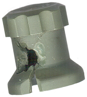
The Function (FCTN) knob on the RT-1439 is a poor design. When used it's necessary to pull the knob out to get to some positions.
The repair is to use a very small amount of J-B Weld to epoxy the metal insert into the knob.
Marking on the bottom edge of the skirt:
MFR-31550 (ITT Ft. Wayne, IN) 80053 ASSY A3147839-1
PS Magazine
| Title |
Class |
Sub |
Yr |
# |
pg |
Related Equipment
GRA-39 Field Wire Remote Control -
KY-57 Voice Encryption -
OE-254 Antenna -
PLGR GPS receiver (only for use with RT-1523A,B,C,D,E)
CV-4228 Fill Cable - all SINCGARS radios & KY-57
MX-18290 Fill Device (All SINCGARS radios)
Tool Kit 101 - PS Mag 1999 # 557 pgs 44-48.
Links
Global Security - SINCGARS-V - Background paper on SINCGARS
FAS - SINCGARS training -
EIB Training - Operate SINCGARS Radio -
Jerry Proc's SINCGARS web page
Signal Magazine - Redesigned Communication Equipment Strengthens First-to-Fight Operations -
Back to Brooke's Products for Sale, Military Information, PRC-68 Family of Squad Radios, U229 Audio Accessories, Audio Connectors, Electronics, Home page
[an error occurred while processing this directive] page created 4 May 2005.