The
Secret History of Silicon Valley (56 minutes) Google Tech Talks, Dec 18 2007
by Steve Blank is a very interesting overview of Electronic
Warfare and how Stanford professor Terman helped develop the west
coast infrastructure. Highly recommended. The cost in
human lives is has a noticable impact on Steve. Hidden in
Plain Sight (1:02:45) at the Computer Museum, by
Steve Blank, Nov 20, 2008 - a very similar talk
The PDF version is as it appeared originally and contains all the
illustrations, some of which may be missing or distorted in the
html version. Moon
Bounce
Elint - PDF
- a CIA paper was SECRET NO FOREIGN, declassified 2
July 96 - why the Stanford 150 foot dish is one of the best for
Moon Bounce ELINT QUALITY
ELINT - PDF
- a Feb 1968 CIA paper was SECRET NO FOREIGN, declassified 2
July 96 - looking at antenna patterns along with actual power
levels. An
Elint
Vigil, Unmanned - PDF
- a CIA paper was SECRET NO FOREIGN, declassified 2
July 96 - about the SA-2 SAM system (one of the systems the
Limiter Detector was developed) a proposed automatic system (was
it deployed?). Communist
Defense
Against Aerial Surveillance in Southeast Asia - a CIA
paper was SECRET NO
FOREIGN, declassified 2 July 96 - all illistrations
at end of paper THE
OXCART
STORY - a CIA paper was SECRET, declassified 2 July 96 -
about the A-12, aka SR-71 SCIENTIFIC
AND
TECHNICAL INTELLIGENCE ANALYSIS - a CIA paper was SECRET,
declassified 2 July 96 - includes mention of SA-2 & SA-6 ELINT
a
Scientific Intelligence System - PDF
- 12 page overview formerly SECRET declassified 22 SEPT 93 The
U.S.
Hunt for Axis Agent Radios - PDF
- Official Use Only
declassified 18 SEPT 95 -
The mechanical shutter based APR-25
Radar Warning Receiver was modeled after an early Police Radar Warning Receiver. So the
stories about pilots jury rigging automotive police radar
detectors into aircraft may be true.
Carrier based aircraft operating near Vietnam were supposed to
turn a manual switch on their Radar Warning Receiver (RWR) to
short out the receiver before they left the plane. They were
also not supposed to activate any of their radar's while on
deck. If both of these rules were broken the result would be
that the RWR with the switch in the receive position would have
it's front end burned out. The pilot would not know this
until he was attacked with no warning from the RWR. Hence
the need for a Limiter-Detector that would be immune from this
problem.
The soviet block surface to air weapons were the SA-x missiles
and the ZU-23 gun.
When a gun is mounted on a truck it may be called a Technical (Wiki)
or Gun Truck (Wiki) if it
has some armor or Improvised fighting vehicle (Wiki).
This was a game changer system that was/is capable of shooting
down aircraft flying at over 60,000 feet. Developed in
1957, shot down a RB-57D (Wiki)
over China in 1959 (but they claimed a fighter shot it
down). The first public shoot down was the U-2 of Francis
Powers in 1960 (Wiki).
The Spoon Rest early warning radar (Wiki: P-12)
operates at VHF. Note search radars typically operate at
low frequencies while tracking/guidance radar's operate at short
microwave frequencies. In 1999 it played a part in
shooting down an F-117 (Wiki).
The Fan Song Fire control & tracking radar (Wiki)
operates in what's now called E (2 - 3 GHz), F (3 - 4 GHz)
and G (4 - 6 GHz) bands.
The Radar Warning Receivers and Anti-Radiation Missiles (Wiki),
like the Shrike (Wiki,
see below) or HARM (see below)
were developed to cope with this threat. This also had a
major impact leading to the development of nap-of-the Earth (Wiki)
aircraft like the F-111 (Wiki),
the A-12 (Wiki)
designed from the ground up to have radar stealth (Wiki)
capabilities and the start of spy satellites (Wiki: Corona)
which were controlled from the Blue Cube (Wiki: Onizuka
AF Base) in Sunnyvale, CA.
Spy Satellites
I moved this to the China Lake patents page because the Navy was the
father of GPS.
Modules
This idea is to use raw diode chips instead of diodes mounted
in packages because at microwave frequencies the package
parasitics (capacitance and inductance) greatly degrade
performance.
At the time I was working at Aertech Microwave and we had just
started to make microwave modules. These were patterned
after the HP comb generator and PIN diode switch modules that
were cylinders about 1/4" in diameter with glass to metal seals
in each end. The HP design sealed the outer sleeve to the
module using a welding process that left the end
rough. To get a good joint HP had a recess that was
the mating surface for microwave contact. This was a
difficult thing to mate without adding an extra part and so was
more expensive than our way of doing it.
I designed our module so that the mating surface was proud of
the rest of the module on each end and used a solder process to
seal the module. Rather than use an iron to solder we used a Seven Associates single
turn inductive heater with the module held in vertical position
so you could see the end under a microscope. A solder preform
was placed in the groove designed for this purpose and the
heater start button pressed. In a few seconds the solder
sealed the module. The module would then be leak tested
using Helium. Helium is the smallest molecule available
for leak testing, Hydrogen is a diatomic gas and has a module
that's almost twice as big as Helium. Helium leaks out of
balloons much easier than hydrogen, that's why Mylar helium
balloons stay aloft much longer than rubber ones.
Rucker & Kolls and Micromanulipator were the common
analytical probe stations that we used a lot. These
have a level horseshoe ring that moves up and down
relative to the chuck. A stereo zoom microscope and an
illuminator would complete the station, plus the probes
and test equipment. The micrometer head sets the
down height of the horseshoe. The black knobs on
either side raise or lower the horseshoe. You can
see a double sided socket for a plug-in PCB below the
horseshoe and there were (are?) companies that would make
up probe cards with the tips where you wanted them so you
could use either a plug-in card or individual probes
mounted on magnetic mounts, each with it's own
positioner. The knurled knobs in the front are the
X-Y stage adjustments. The black knob at the very
front is for stage rotation.
Aertech had a
number of different modules in our product line including
switches, comb generators, limiters and detectors. A need
came up for a combined limiter detector for a classified military
program related to Vietnam. This was for a Quick Reaction
Contract (QRC). These contracts typically carried a
government priority rating of DX-A7 or DX-A2. This meant
that we could get our orders delivered before any civilian got his
parts and it also meant that the program was watched very closely.
The common RWR at this time was called a "Crystal Video"
microwave receiver because it had no RF amplification ahead of
the detector and no mixers or Local Oscillators. These
were really just Crystal Radios that work at
microwave frequencies. An early patent for a Microwave
Filter and Detector filed in 1958 and granted 1960 is US 2954468.
The "filter" grew into a multi band device called a tri-plexer
or quad-plexer (aka: multi-plexer). See: ALR-54 Lamps.
We used Kulicke and Soffa and other makes for wire bonding (Wiki).
We used gold wire, we did not use aluminum (Wiki: Purple
plague), like the commercial semi companies. This is
because a layer of gold was put on as the top contact of the
semiconductor diode chip. Pure gold wire will weld to the
gold bonding pad when some magic combination of pressure and
temperature is present. That pretty much always meant
heating the capillary or wedge and maybe in addition heating the
stage holding whatever was being worked on. Sometimes
using an ultrasonic holder for the capillary or wedge would add
heat. The resulting gold-gold bond can pass military
specs.
Note a capillary combined with a flame to cut the gold wire
leaves a ball on the end of the gold wire so pressing down with
the capillary tip will bond the ball to the diode. The
wire can then be routed to the next pad and a wedge type bond
made there. Pulling up allows for another flame gold wire
cut and a new gold ball. 4202482
Solenoid actuated wire feed and tearing apparatus, Moshe E.
Sade, Albert Soffa, Dan Vilenski, William Wing, Kulicke
and Soffa, 1980-05-13, - 4239144
Apparatus for wire bonding, Richard J. EllesFrederick W.
Kulicke, Jr.Moshe E. SadeAlbert Soffa, Kulicke
and Soffa, 1980-12-16, -
2954468 Microwave filter and detector, George
L Matthaei, Northrop Grumman (TRW),
1960-09-27, -
This design uses a packaged diode (40), similar to the 1N21 so it
can only work over a narrow bandwidth.
PS the back (tunnel) diode
detectors made at Aertech have low impedance, unlike
the high impedance crystal diodes, and so
naturally work over wide RF and video bandwidths.
This
Detector (no limiter) has a meandered ceramic matching section.
I made up a special housing to hold our separate limiter and
detector (LD) in a long tube. On one end was the microwave
input SMA(m) connector and on the other end was the connector
for the detector output.
I took this prototype up to the Applied Technology Inc.
building on a hill in the Stanford Industrial Park. It had
a great view of the Palo Alto bay area. Inside there was a
room with walls formed by chain link fencing that went all the
way to the ceiling. The gate was open and there were men
inside carrying snub nose 38 revolvers.
We tested the prototype by applying radar level power levels
(accounting for the path loss across a carrier deck) then
checked to see of the detector was fried. It passed.
Limiter-Detecton
in
a single package. I bent the leads to get the module to
stay upside down on the scanner. (the modules would
normally sit right side up for the same reason that a submarine
stays right side up, i.e. it's a boat not a ship.) The two
black dots to the left are the shunt limiter diodes, then a 1/4
wave ceramic transformer with a Schottky diode mounted at the
right end, then a ceramic capacitor. I next designed a way
to package a combined LD in a single longer module and add a
housing at the back to hold the factory select bias resistor and
blocking capacitor, DC bias terminal and Video output terminal
and have the mounting holes and RF connector be in the same
place as the original detector. This was a form, fit and
function replacement that included both Limiter and Detector
functions..
This is a reject unit without the rear (right end) cover
installed. The back end housing was made from a piece of
square Aluminum stock with a single round cavity (easy to make
with a milling machine or screw machine). The printed circuit
board (PCB) that went into the housing was circular in shape
with a diameter that matched a punch that was already in our
machine shop. The PCB could be made up in advance with a
range of the common resistor values used for setting the
detector bias and once the operators had determined the correct
bias the correct box would be mated to the limiter detector.
The square box contains the bias circuit and positions the DC
input and video output connectors in the same location with
respect to the mounting holes as the original ATI
detector. The back of the box was bored in a milling
machine with a single cylindrical hole. The PCB was
punched using a Rotex so it would be circular and fit the milled
hole.
The ALR-xx systems that used these LDs covered a very wide
frequency range. This was handled by using a triplexer (or quadraplexer) to
split the input frequency band into narrower bands. The
exact frequencies were classified. We built the LDs in
various bands to match the requirements for each system.
Another version was the Switched Limiter
Detector where the limiter DC return was brought out on a
connector. That way you could apply a bias to the limiter
diodes turning them on as PIN switches. This allows the
detection of a CW signal. This is a prototype unit.
An earlier version applied the limiter diode bias from the back
end of the module, but that did not work because there was cross
talk between the diode drive signal and the detector output.
The modules were tuned in a clean room using various test
setups. Early on we used the Systron Donner small sweep
oscillator that had a box full of signal generator heads and
switched between them to get a wide band sweep. The setup
included either an HP Scalar Network Analyzer (SNA) or shortly
later the 8410 Vector Network Analyzer (VNA). There were
some simple things that could be done to determine how to
improve the VSWR by the use of the VNA that were not possible
with the SNA.
A good VSWR that was obtained by good matching was far superior
to a good VSWR that was obtained by loss. This made our
LDs more sensitive and at the same time they had the limiter to
protect from carrier zapping.
The Wild Weasel (Wiki)
project is documented in a short movie produced by the Association of Old Crows
called "First In, Last Out" that chronicles the early days of the
Wild Weasel program.
Also see: AGM-45
Shrike Ref 10. "First
In, Last Out" Ref 18. "The Hunter
Killers" Ref 43. Wild Weasel
1: Super Sabre vs SA-2 Guideline In Vietnam
use CTRL F so search this page for "Wild Weasel"
Crystal Video & Aperiodic
receivers
A big advantage of the crystal video receiver is it's
simplicity (no local oscillator, no mixer, no IF amp) which
also means lower cost than a hetrodyne type receiver.
The down side is that it is not as sensitive. But for
some applications sensitivity is not the key parameter.
All the devices in this paragraph are functionally crystal
video receivers, that's to say they are Crystal Radios (Wiki).
Also see my Crystal Radio web
page.
A Crystal Video receiver consists of an antenna, detector and
video output. It covers a wide input band and there's no
tuning required. The crystal video detectors on this
page were built for specific (often classified) microwave
frequency bands (that corresponded with various Surface to Air
Missiles or guns). These typically include a multiband
filter (tri-plexer, Quadra-plexer) with a detector optimized
for each filter output (see the AM-6536/ALR-54 for an example).
TechLib - Area 50 - The Bug
Duster - has two modes: Normal where the antenna feeds a
diode so only works for modulated signals, Pseudo-Sinitsa mode that
can detect CW carriers. The 1N5711 is a guard ring
Schottky diode and so has much more capacitance than a similar
diode without the guard ring. Changing to a lower
capacitance diode should allow operation at higher
frequencies. Crypto Museum - Sinitsa
Синица Body-worn intercept receiver - 30 MHz to 1
GHz. There appears to be a way to detect that one of
these receivers is nearby based on the block diagram. (or
maybe by sending a CW signal and looking for harmonics?)
3939476
Passive ranging tail warning device, George
W. Leopard, Kirby
Hair, App: 1959-05-19, Top Secret, Pub: 1976-02-17, -
"There are at present three systems in use for warning a pilot
of other aircraft in vicinity. They are passive, transponder,
and tail warning.
The passive system consists of a receiver which
detects signals from the radar transmitter in another aircraft
and causes an alarm to be actuated. (i.e. RWR)
The transponder system requires a cooperating
transponder to be located in the unknown aircraft which is
interrogated by the pilot in the aircraft being protected.
The radar tail warning system employs radar echoes and
indicates position and range of other aircraft located in a
cone off the tail of the protected aircraft."
- patented system uses delta time between direct pulse from
other aircraft and ground reflection (along with known
altitude of self) to determine range to other aircraft.
Police Traffic Radar Warning
Receivers
The unit I used when driving the 427 Cobra was the Valentine
1 Radar Detector. The V1 was designed by a member
of the Association of Old Crows. A very sophisticated
unit compared to the first generation detectors shown below.
The military Radar Warning Receiver components I worked on
were for detecting pulse modulated RADAR signals so the input
had modulation. A closely related crystal video receiver
was the Fuzz Buster (Wiki)
for detecting the CW signal from a police speed RADAR.
It used a couple of W.W.II surplus microwave diodes (1N23?) in
a waveguide (Wiki).
One end of the waveguide was the horn antenna. Just
behind the antenna the first diode was modulated by a square
wave signal at an audio frequency (1 kHz?). The audio
frequency will not propagate in the wave guide so the second
detector diode only responded to the change in strength of the
RADAR signal. A narrow band audio amplifier followed the
detector diode. Note a high Q narrow band audio
amplifier followed by a meter is the HP 415
meter. Although made for VSWR (Wiki)
measurements, it's also great for doing lab work on something
like a Fuzz Buster. This is because the narrower the
bandwidth the weaker a signal can be detected.
An improvement on using a square wave, like in the Fuz Buster
would be to use a pseudorandom (Wiki: PR)
on/off modulation and a correlation detector. This is also
called a Lock-In Amplifier (Wiki).
I worked with an engineer from England who used this technique
to measure the step response of a steam powered electrical
generating plant. It would be impossible to make a direct
measurement since changing the input steam pressure from zero to
full blast all at once would destroy the turbine. So he
used a piston on the input steam line to make a very small
change to the input pressure. The piston was modulated
with a very long pseudorandom code and a correlator sensed the
output. Analog Devices makes Synchronous
Detectors for doing this and AFAICR some of these also
have a PR source. I did not see the part I remembered,
maybe it was the ADA2200
or AD630
? These can see signals 100dB below the noise level.
The common Boy Scout crystal
radio is very similar and uses a tuned tank circuit to
select the desired station.
I have a Wi-Fi detector that is a crystal video receiver with
an LED bar graph display. It consists of a patch
antenna, a bandpass filter, an RF amplifier and a detector
followed by an analog circuit driving a LED bargraph display.
Tunnel (really back diodes)
make excellent microwave crystal video detectors because the
diode impedance is near 50 Ohms so not only provides very good
input microwave frequency matching but also provides a very wide
bandwidth output signal source from near 50 Ohms so great for
seeing the true shape of narrow pulses. The common crystal
microwave detector that harks back to the 1N23 point contact
diode (Wiki)
has a high output impedance and so is not good for wide
bandwidth signals, like RADAR pulses.
Radatron was the pioneer company making police radar warning
receivers. They were rather crude, but worked and were
the basis of the military RWRs that this page is about.
This may be the first police radar detector.
All the current Radar Sentry and Driver Alert units on eBay
look identical to me. They have a single wire to clip
the unit onto a sun visor and are powered by a couple of AA
size Mercury batteries.
The first units were called Radar Sentry and Driver Alert
(what's the difference? Let
me know).
Radar Sentry
This photo I received of a Radar Sentry from Pat L.,kc2rnn.
shows a sheet metal sun visor clip. Maybe that's a
newer version?
Fig 1 Radar Sentry, with Sheet metal
sun visor clip.
Fig 2 back of different unit
Note wire sun visor clip, 1N2x series W.W.II vintage
diodes.
Note dielectric rod antenna socket at 45 degrees.
Fig 3 Inside of battery cover shows:
* Mallory ZM9 Mercury AA size batteries,
* Removable Dielectric Rod antenna.
Fig 4 the sheet metal sun visor clip
looks like it does not belong.
Fig 5 Behind the bump in the rear
plastic cover there are
a couple of 1N2x diodes on a
slot antenna for S-Band.
To the right is the working end of the dielectric rod
antenna for X-Band.
Note dielectric rod antenna socket at 0 degrees.
My Radar Sentry
Fig 10
Fig 11 Battery compartment on bottom
Blister for S-band, Dielectric Rod for X-band.
Fig 12
Fig 13
Fig 14
Fig 15
Driver Alert
X & K Band
This is a newer unit that covers a higher frequency band (Ku)
than the Radar Sentry or Driver Alert which cover S and X
band.
I'm guessing the yellow light/button lights up when a radar is
detected and stays lit until it's pressed to silence the
alarm.
The red LED is probably a power is connected pilot lamp.
It would be a bad thing if the cigarette lighter plug came
loose and you didn't notice.
Unlike FuzzBuster, the X K model has a plastic cover on the
horn antenna.
Fig 1
Fig 2
Fig 3
Fig 4 To open:
Remove 4 each 1/4 hex head screws from rear panel
Remove knob, washer, nut from front panel
Fig 5
Fig 6
2 each cartridge diodes
mounted so that their penetration
into the waveguide and be adjusted (Tweaked).
Fig 7 Projects Unlimited X10W12 module
has wires:
Radatron &
related Patents
2901613
Detector for modulated and unmodulated signals, Hubert
H Patterson, George
H Webber, AEC,
1959-08-25, 329/370; 327/50; 455/337; 455/280
- for 200 to 10,000 MHz. "...three separate components:
a broadband antenna, a crystal detector mount, and a
high-gain amplifier with provision for either a
speaker or earphones."
This is the heart of a crystal video receiver.
Why did the AEC want one in 1957? Let me know.
This patent calls a number of prior art patents for
receivers for CW and/or pulse signals, but not
microwave.
3094663
Microwave signal checker for continuous wave
radiations, Vernon
H Siegel, Radatron
R&D Corp, App: 1962-08-03, Pub:
1963-06-18, 455/324; 330/10; 342/20; 343/767; 455/130;
455/226.1; 455/325; 455/347; 375/338 - Includes
removable dielectric rod antenna, see US7889149.
Fig 1 & 2: Note two W.W.II
type diodes mounted on rear wall. Much lower
cost than the machined part needed for 2901613 above,
but using the idea from it.
Fig 13 & 14 removable dielectric rod antenna.
The Radar Sentry uses two of the Mallory ZM9,
Ray-O-Vac M 15 1.35 V Mercury batteries.
3257659
Counter-detection system, Vernon H Siegel, Radatron
R&D Corp, 1966-06-21, 342/20; 342/13 -
Fig 1: a Radar Detector.
Fig 2: Radar Detector at left returns a signal to the
police radar (at right) that contains the modulation
of the RWR chopper so the police radar can detect that
it's being detected.
D194976 Housing for an electro-magnetic
wave detector or similar device, William L. Waytena, Radatron
R&D Corp,
The design patents does not show a sun visor clip, but
otherwise looks like the
Radar Sentry or Driver Alert.
The March '62 ad mentions 1000 hour
Mercury battery.
Dual Band means S and X. But what signal in
S-band was there?
FuzzBuster
When connected to 13.6 VDC nothing happens until the
sensitivity knob is turned CW and at some point the light
and a tone are heard. So maybe this is a working
unit?
There are two diodes in the waveguide casting. The
diode near the horn antenna (Wiki)
is modulated with a square wave and that introduces AM
modulation on the CW Doppler Radar (Wiki)
signal. Note that 10.525 GHz is not one of the ISM
Bands (Wiki)
but rather is allocated for radar use (Frequency Assignments SHF).
The second diode acts as a conventional crystal detector
to recover the AM modulation. There are two
fundamentally different ways to demodulate this
signal. The crude way would be to just amplify the
detector AC output and use a threshold detector or
slightly better add an audio band pass filter. But a
far better way would be to use Lock-in amplifier (Wiki)
technology which may have been too complex
Dale Smith is credited as the inventor of the
FuzzBuster. Note it's a huge improvement on the
Radatron units in that it has a decent antenna.
Meaning the detection range for the FuzzBuster is much
better than the first generation Radatron and probably the
second generation Radatron since most people will lose the
dielectric rod antenna since it's easy to remove.
FuzzBuster pioneered the use of a Full Wave Bridge
Rectifier in series with the DC power cable. This
way the installer does not need to be concerned with the
DC polarity thus eliminating problems with prior art
detectors if the power supply polarity was reversed
probably burning out the receiver.
Photos
Fig 1
Fig 2
Fig 3 The Allen screws lock down the
diode position. They
are adjusted by moving up/down using the rods.
Fig 4 The 4 diodes in the lower right
corner make the input polarity
a non issue. For example if a trucker cuts off
the Cig plug he can
connect either wire to + or -. This may be the
first use of a bridge
on a DC input device?
Fig 5 14-pin DIP IC marked:
072025005
F7742
DJAKARTA
What is it? Let me know
I've been told it's equivalent to the NTE912
Reverse Engineering
IC
The NTE912 "The NTE912 consists of five general–purpose
silicon NPN transistors on a common monolithic substrate
in a 14–Lead DIP type package. Two of the transistors are
internally connected to form a differentially–connected
pair. The transistors of the NTE912 are well suited to a
wide variety of applications in low power systems in the
DC through VHF range. They may be used as discrete
transistors in conventional circuits. However, in
addition, they provide the very significant inherent
integrated circuit advantages of close electrical and
thermal matching."
Pinout table, Notch at top center of table. Another
name for this IC may be CA3086.
It's use is described in App
Note 5296, even though the app note is for the
CA3018.
Pin
Func
Func
Pin
1
Q1 C
Q5 C
14
2
Q1 B
Substrate/
Q5 E
13
3
Q1/Q2 E
Q5 B
12
4
Q2 B
Q4 C
11
5
Q2 C
Q4 E
10
6
Q3 B
Q4 B
9
7
Q3 E
Q3 C
8
Microwave Diodes
Note the Radatron (see above) uses
1N21 type cartridge diodes but the
FuzzBuster is using a much smaller diode. The brass
rods that trap the diodes are 0.0875" dia. The smaller
diodes will have smaller parasitics and will work better at
higher frequencies.
The diode near the horn is the modulator and the other the
detector.
Diode mode (1.0 mA test current, Fluke 87V DMM)
Modulator
Detector
Black to casting
0.565 V
0.431 V
Red to casting
OL
1.966 V
This implies two different diode types are used.
Maybe a PIN and some type of Detector?
When the FuzzBuster is powered up the AC voltage on the
modulator diode is 1.13 VAC and the frequency is about 800
Hz (Fluke 87V DMM).
Valentine 1
This is probably the most sophisticated police radar
detector on the market. See my Cars web page
for more. Mike Valentine makes the Valentine 1 radar
detector (factory,
my cars
page). Rather than use the old fashioned crystal video
detection method he uses a hetrodyne type receiver (Wiki)
and processes the Intermediate Frequency (Wiki)
in a way similar to a spectrum analyzer. That's to say
the receiver can recognize multiple simultaneous signals and
so warn the driver of a number of parameters: is the radar
gun in front, at the side or behind you (based on multiple
antennas), what frequency band is the radar (based on the
design of the LO and IF frequencies), and how many radars
(based on counting the peaks in the spectrum analyzer
display). This is the ultimate in police radar
detectors.
Fox
Labeled the "Super Fox", rear label "Super Hetrodyne Radar
Receiver".
This is the same method of detection as the Fuzz
Buster, i.e. a diode modulates the incoming CW signal
and another diode detects the now modulated signal.
4318103
Compact radar detector and range extender, Donald
L. Roettele, William
E. Yohpe, Fox
Electronics, 1982-03-02, -
"A plano-convex dielectric lens extends across the
aperture and cavity and introduces a microwave phase
delay decreasing from the center of the cavity towards
the tapered wall portion of the horn antenna to
compensate for the deficiencies in the compromised
design of the antenna and for significantly increasing
the sensitivity and gain of the detector."
This has the look and feel of a Fuzzbuster (shown as
Fig 1, marketed by Electrollert Corporation) except it
has an improved antenna.
5666120
Detector apparatus, Chris R. Kline, Bruce A. Ricker, Hans A.
Kvinlaug, Craig R. AutioS, ubhash C. Sakar, Leonard J.
Umina, Whistler Acquisition Corp, 1997-09-09, - both
microwave and optical detection.
Police Traffic
Speed Radar
The first popular police speed CW Doppler (Wiki)
radars operated at 10.525 GHz. This frequency is used
for Doppler motion detection modules like for door
openers. The Fuzzbuster was a crystal video receiver
that consisted of a horn antenna followed by a wave-guide
with a couple of W.W.II detector diodes. The first
diode was driven with a square wave that added modulation to
the incoming signal and the second diode detected the
modulated signal. An AC coupled amplifier made the
detected signal large enough to trip an alarm.
Even though these first generation police RWRs were not
very sensitive they worked because of the RADAR range
equation (Wiki),
that's to say the power level at the RWR is inversely
dependent on the range squared but the power available to
the receiver in the radar gun is inversely dependent on the
range to the fourth power, so the RWR is working with a much
stronger signal that the radar gun.
used the Klystron tube
(Wiki)
"invented in 1937 the the Varian Brothers.
2242249
Electrical converter, Sigurd
F Varian, William
W Hansen, Stanford,
App:1938-06-18, Pub: 1941-05-20, 315/5.44; 315/5.24; 315/30;
315/39; 331/81; 313/147; 315/5.46;
331/79; 333/231 -
1 GHz operation Klystron
2242275 Electrical
translating system and method, Russell
H Varian, Stanford,
1941-05-20, 315/5.31; 313/148; 313/297; 313/337;
313/348; 315/5.48; 330/45; 331/79;
331/83; 333/230 -
The
following patents are cited as prior art by Police Doppler
Radar speed measuring patents.
2422064
Ground speed indicator (Drift Indicator) , Earl
I Anderson, Barco
Allen, RCA,
1947-6-10, - Aircraft 2477567Means
for detecting presence and movement of bodies, Eastern
Ind Inc, Oct 7, 1944, Aug 2, 1949,
- 342/69, 246/30, 342/109, 340/936, 342/114, 340/935, 246/182.00A, 340/552, 342/128, 340/933 2479568
Doppler radar system, William
W Hansen, Sperry
Corp, App: 1943-08-19, Pub: 1949-08-23, - UHF,
involves Doppler processing 2540076
Radio cycle summation measuring apparatus, Oscar
H Dicke, App: 1944-09-28, Pub: 1951-02-06, - for
surveying distance as accurate as frequency accuracy. motor
drives chain of decimal pointers to null Doppler. also
see radio
altimeters 2535274
Moving target indicator, Robert
H Dicke (Wiki,
Pendulums),
Sec of War, App: 1945-04-24, - "Doppler effect"
3438031
Doppler radar having digital speed indicator, RE29401
Method and apparatus for digitally measuring speed 3689921
Method and apparatus for digitally determining the speed
of a moving object 3936824
Method and apparatus for digitally measuring speed
4214243
Harmonic detector for traffic radar, - inhibit for moving
radar (i.e. in moving police car).
Doppler Modules
At Aertech
I worked on a proposal that included testing a Hittite
GaAs IC that was a complete FMCW Doppler radar.
AFAICR it was for use in artillery shells and allowed
setting the fuze for the distance above ground.
Nothing came of the proposal.
I seem to remember a number of companies working on
Doppler Modules since there were many high volume
applications. Automatic door openers was the highest
volume, but alarm systems, vehicle crash avoidance systems
were popular until the lawyers nixed that idea. Aertech
was going to make some hardware for a microwave aircraft
collision avoidance system, but no bid because of the
liability being so high.
The ME-400 I labeled as an
Indoor Doppler Intrusion Sensor, but I'm rethinking
that. In order to get a Doppler signal there needs
to be a mixing of the Tx and Rx signals that will produce
a usable output level. I doubt a single active
device can do that. For example the HP 35200A has a very poor mixer,
but did get enough signal so sort of work.
These are different than the proximity fuzes developed
during W.W.II. See: China
Lake patents.
HB 100
This may be the most common Doppler module.
Frequency: 10.525 GHz
Input: 5V <= 40 mA
Range: >20 meters (65')
Note the "QA sticker"is over the DRO. There is a
slot in the PCB next to the DRO.
There are four patch antennas adjacent to the electrical
connection terminals.
The "IF" output is at audio, so I ordered a small "my amp"
battery powered audio amp/speaker.
The can should face away from the target. You can
see the four antennas in Fig 3 on the PCB.
Fig 1
Fig 2
Fig 3 Two Tx antennas, two Rx
antennas.
RCWL-0516
I ordered a couple and they came as a single panel.
This unit does not have an IF output, only an On/OFF
signal. Intended to replace a PIR.
Frequency: ? GHz
Input: 4 to 28 VDC
Range: >5 ~ 7 meters (16' ~ 23')
GitHub: RCWL-0516
- 3.2 GHz, U1: RCWL-9196, The component side of the board
should face the target.
This is a packaged module. The module has three
terminals, ground, DC in and output.
The green PCB contains an LM317 to drop the input to the
voltage required by the module and the two ICs. It
also has a relay and a terminal block with 4 contacts
(input DC and output relay terminals. In addition a
green LED and a light sensor. So this is aimed at
controlling room lights.
Frequency: 5.8 GHz
Input: 12 to 24 VDC <= 0.5W
Range: 1 to 10 meters
4931799
Short-range radar transceiver employing a FET
oscillator, Cheng
P. Wen, Richard
T. Hennegan, Hughes,
1990-06-05, - Duroid substrate, Gunn diode, power
divider (not circulator) . FMCW so can detect range,
not simple Doppler.
In 1971 HP came out with the 35200A
Doppler Radar module. HP
Measure Dec. 1970 - I remember we got one at Aertech for reverse engineering
and were amazed that it had a design defect. Fred
called me to the microscope to see the bad design. He
was surprised that HP would make such a mistake.
The Gunn Diode (Wiki)
and it's associated dielectric resonator (Wiki)
form at 10.525 GHz oscillator with about 50 mW (+17 dBm)
output.
It drives a circulator (Wiki)
which passes signals in a clockwise direction.
Oscillator -> Antenna -> Band Pass Filter ->
Mixer.
Note the the leakage from the oscillator to the Band
Pass Filter will be down by 20 dB, or only 0.5 mW (-3
dBm) to the mixer.
There's a small amount of loss through the band pass
filter making it a little worse. That means the
mixer does not have enough power to work and this
product was a failure.
PS the HB 100 Doppler module that sells for under $3 on
eBay uses a Wilkinson power divider (Wiki)
to feed the same amount of power (about 13 dBm) to both
the Tx antenna and the mixer. That extra 10 dB of
power (i.e. 10X) makes all the difference between not
working and working.
Fig 1
This is a very heavy device. Note
that the mixer pin has a shorting clip. That means
this pin is susceptible to electrostatic discharge
(ESD). Two more reasons why it did not become
commercially viable. The serial number is
00261. Maybe less than 1,000 were ever made?
YouTube: 24GHz Radar Presence
Detector that Works (LD2410), 13:18, 25 Sep 2022 - has
firmware bugs, draws a lot of power so not suitable for battery
operation. Two modes of operation: use the on board uC
which can be programmed (but with bugs) or process the sensor
data yourself.
eBay search: "LD2410" many hits, starting price
$5.20 for the PCB module. - but only the sensor board, none
include the base PCB.
multiple sensors reviewed at: Home Assistant: mmWave
Wars: one sensor (module) to rule them all -
The Seeed
studio 24 GHz sensor not liked because of extreme
sensitivity. They also make a 60
GHz FMCW Human Resting Breathing and Heartbeat Module.
The Tuya Smart Human Presence Sensor uses the LD2410 module
sells for about $30 in eBay. search term "Human Presence Sensor
mmWave Radar" (5VDC @ 1 Amp) OmniPreSense
OPS243-C has WiFi and Bluetooth.
Aperiodic non tuned wide band
receivers
The aperiodic and Sinitsa receivers are just crystal audio/video
receivers and so belong on this RWR web page that's mainly about
radar crystal video receivers.
The Bug
Duster by Wenzel has a Sinitsa (Crypto
Museum) mode of operation. Some possible
improvements:
During W.W. II the aperiodic receiver was invented (see
patent #2513384
below). The SSR-201 (Wireless
for the Warrior Vol 4) will receive any frequency
between 50 kHz and 60 MHz without tuning, i.e. it's a wide
open front end, or a Crystal Video receiver. Also see
the free on line book The History of the Radio Intelligence
Division Before and During World War II. For example one
of these was at the Japanese interment camp at Thule Lake,
California (Wiki)
and caught the man who had built a transmitter used to talk to
other inmates who had regular AM radios. They used radio
transmissions to coordinate a escape attempt. At this
time AM was used for all voice transmissions so a detector
diode at the front end would work.
Below information based on inputs from Brian KN4R:
CIA Reading Room: D.F.
Equipment - F.C.C. and F.B.I..pdf -
* Finch model F-115-A: vehicle mounted, rotatable loop on roof
(probably hetrodyne receiver)
* Fada Aperiodic receiver - suitcase size
* Kann Mfg. Co. series K Aperiodic - AC powered, relay to turn
on recorder (see YouTube below).
is
---- Below - Transmissions being recorded
on Memorox discs. Each drawer
beneath the amplifier includes a turntable
and a magnetic recording head which
embosses on paper based discs one hour and
five minutes of playing time per side.
The operator here is transcribing signals
which have been previously recorded.
should be
------ Below - Transmissions being recorded
on Memovox discs. Each drawer
beneath the amplifier includes a turntable
and an electromagnetic recording
head which embosses on paper based discs one
hour and five minutes of playing time per
side. The operator here is
transcribing signals which have been
previously recorded.
While the recording head is based on an
electromagnet, it is misleading so say "magnetic"
recording head since that would imply magnetic
recording.
The recording technology is embossing plastic.
In the beginning Aertech used Alfred
Electronics BWO sweep generators, these
literally could be used for boat anchors. They were rack panel width and a couple of feet
tall. Later the HP 690 series sweepers with the
plug-in BWO and snap in plastic frequency scale were used.
It was possible to put a number (3?) of plug-ins in one rack and
the master in another in order to sweep more than one standard
band (standard bands were AFAICR, L = 1 to 2, S = 2 to 4, C = 4
to 8, X = 8 to 12.4, K = 12.4 to 18, Ku = 18 to 26 GHz). Then
the Kruse Stork 5000 solid
state sweeper came out and it too had a combiner for multiband
sweeps. Then the HP 8350 sweepers came out with a single
plug-in for multi-band sweeps and later multi octave band
plug-ins. These had poor phase noise, but for most
microwave components work worked well. You could tie two
together for mixer work. Then there were the synthesized
sweep generators with excellent phase noise that were required
for precision mixer work.
This is really a very narrow band AC voltmeter centered on 1
kHz. Maybe a few Hz bandwidth. When working with
weak microwave signals you can 100% AM modulate the RF (either
using the internal 1 kHz modulation feature of the sig gen or an
external PIN diode modulator) then feed the output from a
detector to the 415 meter. Originally these were used for
making slotted line VSWR measurements, but can be used for other
applications.
This is the only meter that I was aware of that could make such
a wide band true RMS measurement. Used for making noise
measurements in a number of applications.
I owe John, WA4WDL, a huge debt of gratitude for making
me aware of this. This came up while learning about the FuzzBuster and the early history of
RWRs. Note that the APS-nn
designation is normally used for Airborne Search &
Detection Radars. So the first part of this will be looking into
the idea that this is a Radar Warning Receiver. This unit is
listed as:
"Tail-Warning
Radar System; manufactured byITT; used inB-47B/E,B-52,B-57A,B&C (On/Off,
Delay: On/Off, Noes/Both/Tail, Audio Gaini, Phones On/Off, Test
Momentary/Off, Power On/Off),EB-66B,F-101A/C (On/Off, Delay In/Out,
Audio Gain; Nose/Both/Tail),F-105D, "EF-101B"
(Canada)".
Thanks to Jan for copies of the B-571a,b&c manual pages as
well as F-101A manual pages. The functionality looks the
same for both. RADAR and visual sensors in both the nose
and tail. Audio with PRF into the AIC-1 audio system.
Note: Tail warning radars were tried in W.W.II, such as the APS-13,
which was discontinued since it acted as a beacon for enemy
fighters. The APS-13 did see service in the Little Boy and
Fat Man atomic bombs as an altimeter. So it's probably a
bad idea for the B-52 to use a tail warning radar, but makes a
lot of sense to have a tail warning receiver.
Photos
Wanted images of any part of the APS-54. Let me know.
The below images courtesy of John, WA4WDL.
Fig 1 AM-924/APS-54 Amplifier, Video
Fig 2 AM-924/APS-54 Amplifier, Video
Note there are two Antenna Jacks and
two PRF Lower Limit Selector switches.
It may be that this is the heart of the system.
The antennas may have video outputs instead of RF.
See the AM-6536/ALR-54 RF box
which has
video outputs.
What is it?
This is looking into the idea that this is a Radar Warning
Receiver, rather than just an Airborne Search & Detection
Radar.
The B-47 Stratojet Association - B-47B
- "The B-47B carried a K-4A bombing navigation system with a
periscope sight in a modified nose, AN/APS-54 warning radar, and
AN/APT-5A electronics countermeasures devices" Vietnam
Conflict Aviation Resource Center - Martin
B-57 Canberra - "Avionics: – APW-11 Bombing Air Radar
Guidance System, SHORAN
bombing system (Wiki), APS-54 Radar
Warning Receiver 3154780
Automatic SHORAN bombing system, Donald
W Burbcck, Elwood
E Bolles, Jr
William E Frady, William
L Exner, James
D Hogan, Alfred
D Scarbrough, AF,
1964-10-27, -
Joe Baugher - Martin
B-57B - "An APW-11 (Radio
Museum: 2.8 GHz)Bombing Air Radar Guidance System was
provided, helping the pilot to make accurate runs into the target.
The Shoran (Wiki)
bombing system was added for use by the bombardier/navigator. An
APS-54 Radar Warning System was provided, which increased the
angle of coverage astern of the aircraft and gave the crew some
warning of AI illumination." QRC
- USAF Quick Reaction Capability Programs - QRC-3: J band (Wiki:
10 -20 GHz) antennas forAN/APS-54radar
warning receiver;Hallicrafters; QRC-5: J band antennas forAN/APS-54radar
warning receiver;Hallicrafters, 1953; QRC-11 Selective J
band antenna for APS-54 radar warning receiver, Hallicrafters,
1954 The Free Library - First
pereson . . . singular. - "There was an APS-54 warning
receiver, which was fairly new, and an ALE-1 chaff dispenser, which was not fully tested
and which I was not allowed to use."..Col Joseph B. Tyra, USAF
(ret.)
Amazon - RF-101
Voodoo Units in Combat (Combat Aircraft Book 127), by Peter
E. Davies, Jim Laurier -
"I would have liked to see some coverage of the AN/APS-54 radar
warning receiver, that was replaced by the APR-25/26. The
APS-54 was used until 1966 or 1967. It could handle the Fire Can (CIA:
2.7 - 2.86 GHz) and the Fansong (Wiki: S-75, SA-2:
Fan Song: 2 -
3 GHz or 4 - 6 GHz) . The radar waveform was fed to the intercom
as an audio warning. The APS-54 had two red warning lights on the
instrument panel marked "Nose" and "Tail". I spent more time
fixing APS-54 problems than my assigned job. The APS-54 had one
antenna under the nose radome, and another on the rear tip of the
vertical stabilizer cap. The BNC connector from the rear antenna
to the stabilizer bulkhead had a habit of pulling apart. Repair
usually involved standing on a step ladder on top of a Coleman
"Tug" (Wiki)
to remove the cap and repair the connector. One of the not so
"fun" repair jobs.
The AN/AHN2 audio recorder is mentioned. This was used to record
the Radar audio from the APS-54 for debreif and training. This was
a Wire
recorder. The recording wire was in a cassette. Wire
breakage was frequent. You had to unsnarl the mess and splice the
wire, then anneal it with a Zippo lighter. Wire recorders were
long obsolete at that time. This one was probably used because it
was smaller than the available tape recorders." Radio Nerds - APS
List - APS-54* ECM Warning Receiver for B-47,52,57,EB-66,
F-101,105 Cape-Farns AS-679,680/APS-54 Antenna Units, 2600-11,000
MC
Description
There may have been a couple of lamps on the pilot's instrument
panel marked "Nose" and "Tail" that would light up if the system
detected a high PRF (Wiki)
indicating the aircraft was being tracked. Note that
search radars have low PRFs so they can have long unambiguous
ranges, but tracking radars need fast PRFs to quickly detect
changes in direction.
Two antennas one in nose and one in tail. The antenna
assembly may include an RF detector with video amplification.
The main box is the AM-924/APS-54 that has two video inputs
and provision to select the minimum PRF. These along
with the Gain and Bias adjustments could be set differently
for different known threats. The Blanking Inputs might
come from Nose and Tail radar sets so that the APS-54 does not
respond to radars on board the aircraft.
A small panel with warning lights marked "Nose" and "Tail".
Based on Police Radar Warning Receivers. All
analog signal processing.
1966 vector receiver (the small CRT showed the relative bearing to
the threat as the angle from center screen, and the distance from
center screen was a relative distance to the threat, made by Itek
used to detect:
S-band emissions from SA-2s
early warning ground-control radars
C-band radiations from the improved SA-2 radars
X-band characteristics of airborne intercept radars
S/X/C-Band Radar Detection and Homing Set; manufactured by Itek;
part of AN/ALQ-27; used in A-7E, U-8, U-21, OV-1D, B-52G, RA-5C,
A-6E, F-4, F-14, F-100, F-105, C-123, C-130
A crystal video receiver feeds
video pulses to a blocking monostable multivibrator with
a 200 micro second recovery time so that the highest
output frequency is 5,000 Hz. In front of the
detector is a shutter which when closed protects the
detector from being burned out by a close by radar (like
on an aircraft carrier when another fighter plane pilot
turns on his RADAR even though he is not supposed to do
that). This is the case that triggered my
development of the limiter-detector.
Patent Citations: 3061795
Flip-flop varies frequency of blocking oscillator, Clarence
G Byrd, William
K Hagan, IT&T,
App: 1958-01-22, Pub: 1962-10-30, - "This invention relates to
circuits for indicating the presence of a radio signal, and more
particularly to a circuit for indicating the presence of a
pulsed radio signal, the indication being sustained for a period
of time longer than an individual signal pulse." So a human can
hear radar pulses.
3094663 see above Microwave signal
checker for continuous wave radiations
Cited by:
3660844
Radar detector and identifier, Basil
E Potter, Sierra
Research Corp, 1972-05-02, 342/20; 455/117; 342/13; 455/229;
375/339 -
4 horn antennas, each for a different frequency band
Also CW and PRF detection, Output by a number of
lights and a single channel of audio
4440987
Computer and peripheral interface circuit, , Tandy
Corp, AST Research Inc, 1984-04-03, -
audio frequency port for modem <-> computer coms
5361069
Airborne radar warning receiver, Robert A. Klimek, Jr.,
Elias A. McCormac, III, Ronald R. Schambeau, AF, App:
1969-07-18, (Vietnam Era - SECRET),
Pub: 1994-11-01, 342/20-
6977611
FM-CW altimeter detector, Ronald T. Crabb, Northrop
Grumman Sys, App: 1985-03-04, (SECRET),
Pub: 2005-12-20, 342/122 -
detects the very weak FM-CW altimeter signal from
aircraft well in front on plane on ground. Maybe
for IFF use?
7148835
Method and apparatus for identifying ownship threats, Jeffrey
K. Bricker, Anthony
J. Gounalis, James
C. Rosswog, Stephen
P. Wanchissen, Lockheed
Martin, 2006-12-28, 342/20; 342/89; 342/195; 342/175;
342/13 - "A track indication may be provided
that indicates at least one source is actively tracking
the object based on the received signals and without
adjusting the dwell arrangement of the scan strategy for
the receiver."
crystal video Radar Warning Receiver made by Itek
Used to sense power-level changes in the L-band command guidance
radars of the SAM i.e. a launch detector.
SAM launch warning system SAM
Launch Warning Set; manufactured by Itek; used with
AN/APR-25; used in F-100, F-4, U-8, U-21
Homing and Warning ECM Receiver (improved AN/APR-25);
manufactured by Itek; used in F-105, EF-4E, A-7, B-52, F-5E/F IP-957/APR-36 - CRT display
showing relative bearing to and type of threat by Applied
Technology Inc (ATI) another view
- Label -
"early A-10's used the IP-957/APR-36 azimuth indicator as part of
the ALR-46 system and the indicator could display alphanumeric
symbols as opposed to simple strobes."
- L.M.
YouTube: TD Wills: MilViz
TacPack F-4E: AN/APR-36 RHAW System Demo -
ECM Signal Can anyone define for me what the "BG06" SAM signal was
and how the EWs "played" with it? I'm a retired Lt. Col.
who flew Ds as a Nav on CAR E-57 during LB II from
Andersen. B... B,,,,,,
Re: ECM Signal BG06 referred to the guidance channel for the SA-2
missile. The missile was tracked by the targeting radar and
corrections to the missile were up linked to the missile via the
BG06.
Since the BG06 antenna was "looking" back at the launch site,
the only way to jam it was to be between the missile and the
site. To do this, either you were below the missile doing
support jamming or you were lucky and the missile missed you.
The radar warning receiver had a launch light to indicate the
BG06 was active. My experience was that the light was
inaccurate. I looked for the signal on my ECM receiver.
TM11-5841-283-12 Operation & Maint Manual, 150
pages, is on line at ETM as PIN 053495.pdf IP-1150 CRT eBay photo
YouTube: RCAF Library: CFSACO
[V] 079 APR 39 XEI Demo -
AS-2890/APR-39(V), NSN: 5985-01-026-3927, Mfr: 33439 - is small
blade type with SMA-f connector.
Components
C-9326 Detecting set Control
IP-1150 Radar Signal Indicator
CM-440 Comparator
R-1838 Radar Receiver
AS-2892 (left) & AS-2891 (right) Sprial Antennas
Made by Texas Instruments. There were a number of
different seeker heads that could be installed, each for a
different target (different frequency band). I designed and
oversaw the production of these Shrike missile detectors. We made a
set of 4 matched detectors for one of the heads. The one
shown is band IX (Wiki).
After properly torquing the SMA nut on the RF (bottom) end a tube
with a flange was slide down and the O-ring seated on the tube
ID. The flange was bolted to the guidance section to support
the detector in the high vibration environment found on an
aircraft wing. A computerized test system was used to
measure hundreds of detectors at a time and output the serial
numbers of the matched sets. We could match much better than
the spec using this system and it improved our yield.
(Another version of this test method was later used by ST
Microwave to match detectors for a satellite program to extremely
tight tolerances.)
Since the frequency band was determined by which guidance
section was installed on the missile, the target needed to be
known before take off.This problem was solved by the HARM missile.
An ammunition reloading press was used to seat some of the SMA
connector pins by meas of a custom die. 4336739
Bullet seating die, Kenneth
L. Alexander, Ammunition Accessories, 1982-06-29, -
The Shrike has the bang-bang (Wiki)
steering vanes located at the center of mass of the
missile. This also causes the AIM-7 Sparrow missile (Wiki)
to move sideways rather than to rotate. Bang-bang control
was also used on most W.W. II vintage torpedoes.
3712228Target
marker warhead China
Lake, CA, Jan
23, 1973
replaces the warhead with a marker
making it easier for others to bomb.
In the YouTube video "The origins of ARM. Defense
suppression and the AGM-45 Shrike antiradar missile" see
Ref
14, @6:50they mention
"Dip Angles" & "Line Up Your Needles". I think the
instrument is an ADI with the needles wired to a Shrike
interface. One needle for Left-Right and one for
Up-Down. The plane/missile needs to be pointing at the
antenna that is to be the target.
AN/ASQ-213 Harm Targeting System (Wiki,
FAS)
- F-15 block 50/52
Made by Texas Instruments. Instead of using
detectors tuned to specific threat frequency ranges like SHRIKE,
the HARM has a wide band mixer that can be electronically tuned to
the desired frequency. It's a Superheterodyne receiver (Wiki)
not a crystal video receiver.
This is the system where we used
the HP 8566B spectrum analyzer to directly measure the spurious
mixer products very quickly. This system was in an access
controlled room and had a number of security features. The
test time was reduced dramatically compared to manual
testing. The HARM could be tuned to any desired frequency so
one missile could be used for whatever target came up.
Unlike the Shrike AGM-45 above where the seeker head determined
the frequency of the radar target.
7 Aug 2022: The Drive: Does
Ukraine Now Have AGM-88 High-Speed Anti-Radiation Missiles? (Updated)
-
8 Aug 2022: Anti-Radiation
Missiles Sent To Ukraine, U.S. Confirms - "...we've included
a number of anti-radiation missiles that can be fired off of
Ukrainian aircraft."
Air Power Australia: Texas
Instruments (Raytheon) AGM-88 HARM -
"The AGM-88 can detect, attack and destroy a target with minimum
aircrew input. The proportional guidance system that hones in on
enemy radar emissions has a fixed antenna and seeker head in the
missile nose. A smokeless, solid-propellant, dual-thrust rocket
motor propels the missile." Ref 22.
Explanation of HARM on soviet block aircraft v. on the F-16, see Ref 29, Ref 56, Ref 57,
The Pantsir missile system (Wiki)
was designed to shoot down the HARM as well as UAVs, helicopters
& cruise missiles. To protect the S-300 and similar
larger systems. 2024Dec25 it shot down a passenger plane
(Wiki: AAF8243)
2-18 GHz Radar Warning Receiver; manufactured by Litton; used in
F-8, F-14, A-4, RA-5C, A-6, EA-6B, A-7, F-100, F-4, F/A-18, CF-104
(Canada)
I think this is the one that we made all the Limeter Detectors
for? Control - Close Up - Label - 3 buttons for enabling or
bypassing the lo, med and high frequency bands, also 3 buttons for
Built-In-Test of the three bands and these double as AAA, AAA/AI
or AI selectors?
AN/ALR-46
Digital Warning Receiver; manufactured by Litton; used
in B-52H, A-7D, A-10, C-130, F-104, F-105G, F-111, F-4, F-5E/F,
RU-21H, OV-1, OV-10, HH-53
Until I found this unit on eBay I
didn't know the Limiter Detectors we made were used in the ALR-54,
but they are.
Radar Warning Receiver for "LAMPS I"
system; manufactured by Itek; used in SH-2D/F, SH-3G/H The AM-6536 uses a number of Aertech Limiter Detectors. Sikorsky S-70B
Seahawk - "Light Airborne Multipurpose System (LAMPS)"
I found the AM-6536/ALR-54 on
eBay. From the photos it looks like the box where the air
frame coax cable from one antenna goes to a single TNCm input
connector on the AM-6536. Inside there's the band separation
filter and I think this unit has 4 Limiter Detectors.
There's 5 video amplifier boards and some other board with 5
channels, maybe threshold and slope adjustments. Some
reverse engineering will be interesting. This unit has had a
hammer taken to it and it's been stored outside for some number of
decades, but I expect it still may be in almost working condition.
Uses the A9X141, A9X142, A9X143 and A9X144 Limiter
Detectors. The overall AM-6536 box has a contract date of
1972.
Dimensions: 6.0 x 6.75 x 3.25 inches Box made by machining a
billet of aluminum that size to remove the cavity inside.
Four of the Video PCBs are fed by the four Limiter Detectors and
one video PCB (XA5) gets it's input from the external TNC-male
coax connector and since the coax on the inside of that connector
has no shield for about 1 inch and it feeds a video amp I'd say it
was a fairly low frequency video signal, not RF, not microwave.
What was it? let me know
This box was part of the very first LAMPS and has been sitting
outside with a cover removed for many decades. A couple of
the transistors on one of the Video PCBs have had their leads rust
away allowing the transistor body to be missing. The
conformal coating could not get between the bottom of the
transistor and the plastic spacing disk. The rest of the
board where the coating is in tact looks good. No op amps,
no ICs, just discrete parts. Not sure what the white growth
on the aluminum is, but suspect it's related to a salt water
atmosphere.
Need to put together a time line for Aertech.
If you know key dates in Aertech's history please let me
know.
ALR-62
Used on the F-111
Antenna: AS-2943/ALR-62
AN/ALR-73
0.5-18 GHz Multiband ECM Receiver (improved AN/ALR-59);
manufactured by Litton; used in E-2C
AN/ALR-100
(also called the LR-100), a lightweight radar signal
receiver designed in-house by Litton Amecom using COTS
(commercial-off-the-shelf) components. It can serve as a radar
warning receiver (RWR) and also provides precision emitter
location and identification (ESM/ELINT) as an electronic support
measures (ESM) system.
All of the Limiter-Detectors I worked on ended up attached to a
multi-band filter, typically called a tri-plexer or quad-plexer. 3215934
System for quantizing intelligence according to ratio of outputs
of adjacent band-pass filters, Roy P
Sallen, GTE
Sylvania, 1965-11-02, -
Polar Frequency Discriminators =
Instantaneous Frequency Measuring
This microwave component is composed of a combination of
power spliters and couplers and contains 4 detectors. One
pair of detectors provides an X value and the other pair provides
a Y value for a vector. The magnitude of the vector is
proportional to the amplitude of the incoming signal and the phase
angle is proportional to the frequency of the input signal.
In order to get higher frequency resolution you can combine a
number of these using delay lines that are increasingly longer so
that the frequency is read using a gas meter approach. In
this way you can make an instantaneous frequency measuring (IFM)
receiver. Note that this receiver can determine the
frequency of an incoming signal on only one pulse. We
made a number of different models of this device. they have
a frequency range that's no more than an octave, else there would
be a frequency ambiguity. Wide
Bnad Systems - makes these
WJ App Note: High
Probability
of
Intercept Receivers in an EW Environment -
Wiki article on Bat
(guided bomb). Patents:
Class 244 Aeronautics and Astronautics
3.2 Missile Stabilization or Trajectory Control
2764698
Control System, Filing date: Nov 23, 1942 - optical system to
control glide bomb 2680578
Glide Bomb, Filing date: Feb 17, 1945 - TV guided 3128061
Automatic self-guidance System for Movable Objects, Filing date:
Aug 11, 1945 Issue data Apr 7 1964 -
uses 4 quadrent optical system
Calls: 1352960WIND-WHEEL ELECTRIC GENERATOR - for farm use 1387850SYSTEM OF RADIODIRECTIVE CONTROL - "...a
boat, air craft, vehicle, or revolving lighthouse..." 1388932
Arial Torpedo - photocell guidance for attacking a ship 1447646
Selenium Cell or Bridge, C.W. Cherry - 4 quadrants - also see 594
Photronic cell 1747664
Apparatus for Automatically Training Guns, etc. on Moving
Objects - 4 quad optical sensor 2070178AIRPLANE NAVIGATING APPARATUS - uses IR so works
in fog as well as daylight 2165800DIRECTION CONTROL DEVICE - radio remote
control 2300742MEASURING AND CONTROL APPARATUS -
prevents hunting 2377589AUTOMATIC AIMING CONTROL - for a gun, uses 4
telescopes and photocells 2403387RADIANT ENERGY RESPONSIVE DIRECTIONAL CONTROL
- quadrant photocell bomb steering 2404942STEERING DEVICE (RCA) 1940 - a beam
with 4 quadrents is aimed at a ground target and the bomb is
steered by the beam. 2417112ELECTRICAL CONTROL SYSTEM, Kettering
(GM) Filing date: Jul 3, 1943 - heat seeking aerial bomb - also
see Kittering
Bug 2421085
TARGET SEEKING AERIAL BOMB, (Bendix), Filing date: Jul 12, 1943
- works with reflected IR 2424193SELF-STEERING DEVICE - 4 photocells 2425558
Direction Control Device, - radio control, very heavy and
complex 2431510
Photocell Multiplier Device, (Farnsworth Res), Sep 29, 1944 -
photo-multiplier tube with 4 quadrants 2457393
Apparatus for Causation and Prevention of Collisions, G. Muffly,
- anti aircraft missile, 4 photocells
When I joined (about 1963) Aertech
was at 250
Polaris in Mountain View.
196? Aertech moves to 815 Stewart in Sunnyvale (or 825 then 815?)
1968 Aertech at 825 Stewart in Sunnyvale
1984 TRW buys Aertech and even though the FSCM number stays 21847
the name changes to TRW Microwave. __?__
Deguigne
Dr. was another Aertech Building on the corner of Thompson
Place. Across Thompson was AMD. At the end of Thompson
was a heliport, but it was not used.
1987 FEI buys 21847 and the name becomes FEI Microwave
1992 (?) most people are laid off and part of Aertech moves to ST
Microwave. EPA
Region
9 Super Fund sites - 825 Note that it's very difficult
to tell what building is causing pollution since the ground water
moves it. The only way is to have test wells on at least 4
sides of a building and compare the upstream contamination with
the down stream, if they are the same then it's not your
building. Driving around the block of Stewart you can count
dozens of test wells.
Radar Countermeasures
Flares are a counter measure against heat seeking missiles,
like the Sidewinder (See China Lake Patents).
Chaff (UK: Rope) is a countermeasure against radar.
There are electronic countermeasure equipment.
Also see China Lake Patents
Ref 48, page 30 Onboard Thermal Jammer (ALQ-144 &
L-166-11E) and page 46 Pyrotechnic flares China Lake Patents Ref 51. GENESIS of
INFRARED DECOY FLARES The early years from 1950 into the 1970s
M-206 Aircraft Decoy Flare: This is an Army flare,
which nominally is 1-inch by 1- inch by 8-inches in size. It is
used by both fixed and rotary-wing aircraft.
Fig 1
Fig 2
The M-206 Flare has been fired, the tube is
empty. It has fired impulser (primer). The
impulser is electrically triggered rather than triggered
by a firing pin.
The M-1 Chaff stick has not been fired, it contains the
payload, but is missing the impulser (primer), so is ready
to be used.
Fig 3 Impulser removed from M-206 flare.
Note held in by O-Ring.
Body dia: 0.495"
Body overall Length (excluding blown paper): 0.519
Flange thickness: 0.045"
Flange dia: 0.620"
Center contact recessed: 0.068"
Fig 4 Marked:
7729423
T0S07L004-436
Impulser is electrically fired.
MJU-32A/B Infrared Decoy pyrotechnic
Flare
Initially I posted this paragraph on the 40mm
grenade web page because the shape of the MJU-32 looked like a
40MM round. Also see the AN-M8
Flare Pistol.
But the igniter has the look and feel of those used on aircraft
Chaff and Flare cartridges so this belongs here.
Marked:
U.S. Navy NAVAIR
Flare, Decoy
MJU-32A/B
1370-01-592-1440 LA49
KCG14E040-001
G14E-B03534
The body OD is 36mm (1.4") and overall length is 148mm (5.8").
The flange at the rear is 1.66mm thick and 37.8mm dia (1.488").
But instead of a small arms primer socket there's what appears
to be a recess similar to that used with Chaff and Flare
cartridges used in countermeasures.
MJU-32/B Aircraft Decoy Flare: This MTV extruded flare
is an improvement of the MJU-8A/B flare. It also is 1.43 inches
in diameter by 5.81 inches long. The lacing of the spaghetti
into the longitudinal holes of the grain is a very
labor-intensive procedure. To reduce the labor cost, the holes
were changed into a “T” shaped slot. Spaghetti no longer is
required in this design. The concept of the “T” slot is that it
would undergo fissure burning and there would no longer be a
need for an igniter material in the slot. After many experiments
with the shape of the slot, the final “T” shaped slot was chosen
as the optimum balance between ignition speed and performance.
Mr. Jeff Mulinix of NSWC Crane is the inventor of the “T” slot.
This flare dates from 1995.
Launchers
It appears that flares/chaff with nomenclature starting with MJU-
can be used in either the ALE-39 (Citizendium) or
ALE-47 (Wiki,
Citizendium)
The ALE-47 Counter Measures Dispensing System (CMDSS) is a
replacement for the ALE-39 CMDS (FAS).
The magazines that hold the round MJU-32 may be interchangeable
with the magazines that hold the square M-206 Flare or M-1 Chaff
sticks. The former is a 1.4" diameter round package and the
later is a 1" square package. But the photos I've seen show
a 5 x 6 array for a total of 30 cartridges. They are all
square or all round.
The ALE-39 made use of an intervalometer (Wiki)
to dispense the flares.
H1603H
Flare with safe-and-arm ignition system, Dennis D.
Deckard, Stanley J. Herold, Donald E. Lagrange, Dennis L.
Mitchell, David
J. Mulinix, Navy,
1996-11-05, -
3827360
Pneumatic launcher and combination flare-ignitor, A
Geimer, 1974-08-06, - "...readily adapted to launch sonobuoys, beacon
transponders, radio receivers or transmitters, chaff and
so forth from airplanes or ships."
Fig 2B is the Eject Vehicle (EV) rocket which is the same
size as the existing ALR-47 round cartridge.
The
AN/AAR-47 Missile Approach Warning System (Wiki)
can trigger the ALE-39 or ALE-47 to launch IR countermeasure flares. Note
the AAR-47 works by detecting the UV
signature of the approaching missile.
Fig 1
Fig 2
Global Security has a page for the MJU-32B
Infrared Decoy Flare. "The MJU-32/B Infrared Decoy Flare
devices are magnesium-teflon based and produce the same fire
ball result as the Mk46 Mod 1c infrared (ir) decoy flares but
incorporate a safer igniter design that requires an external
ignition source."
The MK46 MOD 1C Decoy Flare is being replaced by
the MJU-32/B through attrition.
From Navy Study Material 14313A:
MJU-32/B, MJU-32A/B, MJU-38/B AND MJU-38A/B DECOY FLARES
These decoy flares are conventional pyrotechnic
Magnesium/Teflon/Viton (MTV) flares that are utilized to decoy IR
heat-seeking missiles. These flares are launched from the
AN/ALE-39 Countermeasure Dispensing System and AN/ALE-47
Countermeasure Dispensing Set.
The MJU-32A/B and MJU-38A/B are form, fit, and function
replacements for the MJU32/B and MJU-38/B. Improvements were made
to ignition reliability. These decoy flares consist of a
cylindrical aluminum case approximately 5.8 inches long and 1.4
inches in diameter (Figure 4-13).
The base end of the one piece flare case is flanged to a maximum
diameter of 1.495 inches to fit the counterbore in the chamber of
the dispenser block. The end of the flare case opposite the
flanged base is closed with an injected molded polycarbonate end
cap attached by a 360 degree crimp. The MJU-32A/B and MJU-38A/B
have a (Black) plastic cartridge retainer threaded and sealed into
the base of the flare case.
These decoy flares consist of two major elements: the pyrotechnic
composition (or flare grain) and the igniter assembly. In the
MJU-32/B and MJU-38/B, the complete length of the grain is wrapped
with adhesive backed aluminum foil that extends over part of the
igniter.
In the MJU-32A/B and MJU-38A/B, the adhesive backed aluminum foil
is one-inch wide and covers the gap between the grain and igniter
assembly. The igniter assembly contains a plastic body, two
ignition pellets, and bore sensing sliders. A silicone rubber pad
is located between the end of the flare grain and end cap to
provide for variations in longitudinal dimensions of the parts
with time. It also provides protection for the internal parts by
damping vibration and shock forces. This device requires the
CCU-136A/A impulse cartridge for functioning.
A RADAR countermeasure developed during W.W.II was then
called Window by the British, but Chaff (Wiki)
by the U.S. This consisted of thin strips of Aluminum foil
cut to be a half wavelength long. The trouble was that the
strands tended to stick together. The solution was to use
small diameter glass fibers with a metallic coating. These
do not stick together and you can get a lot more of them in the
same dispenser volume. German words that may be related
are Düppel or Kunstfadenstraengen.
By 1957 tactical aircraft had Radar Warning Receivers and Chaff (Ref 2).
Rope
In W.W.II a long strip of chaff was called rope. This was
used to confuse long range search radar sets that operated in
the HF or VHF frequency range where a 1/2 wavelength is much
longer than required for a microwave radar. This was on
eBay with title: VTG Genuine WORLD WAR II CHAFF to Confuse Radar
70 Years Ago - WWII - It appears to be many feet long.
3" x 3" x 5/8" - Does not look like any common dimensions with
the RR-97/AL Chaff Brick.
Tape dimensions (see Fig 4).
Plain leader tape thickness: 0.009"
Plain tape wrap radial thickness: 0.110"
Plain Tape ID: 2.80"
Foil tape is in two layers total thickness: 0.001"
Foil Tape OD: 2.775"
Foil Tape ID: 1.422"
This thick paper package (5" x 3" x 2") seems to be designed to
tear apart when in windy conditions, like being ejected from an
aircraft. There is a trigger string (see Fig 4 and Fig 5)
which I suspect trips a mouse trap (Wiki)
mechanism that spreads the contents of the aluminum box.
If you know about these let me know.
Note 3"x5" comes about from the used of the Calculagraph to keep track of
the hours worked, i.e. a factory time clock. The card size
was 3x5.
The thing that's strange is that these contain aluminum boxes
which could damage someone after falling out of the
sky. All the other chaff products I've seen would be
harmless to anyone on the ground, but not this one.
Why? Let me know.
The eBay seller claimed this was Korean war vintage, i.e. the
SA-2 (Wiki) was in use so the Fan Song (Wiki) might
be the indented radar which operated between 2 and 8 GHz.
Outside dimensions: 5" long x 3" wide x 7/8" thick.
There are seven different lengths of chaff.
See: Omni Calculator: Dipole
Chaff
Length
inch
Frequency
half wave dipole
GHz
.875
6.418
1
5.616
1.0625
5.286
1.25
4.493
1.375
4.085
1.5
3.744
2.125
2.643
The internal pack width (chaff length) are
left to right:
Top Row: 7/8", 1-3/8", 1-1/16" & 1-1/4"; total:
4.5625"
Bottom Row: 2-1/8", 1-1/2" & 1"; total: 4.625"
M-1, RR-170AL Chaff Countermeasure
This is a stick type chaff cartridge maybe introduced around 1977. NSN
5865-01-048-2137 p/n: 9311402 RR-170/AL
used on: F-4, F-5, F-15, F-16, A-7, A-10
M-1 used on:Army helicopters
made by Armtec.
1" square body 8-1/8" long.
Fig 1
Fig 2
Table of Chaff
Cartridges
"Countermeasures Chaff Container" may be the correct way to refer
to this brick. Found this information using that search
term:
Ref 1. Chaff
Countermeasures and Air Defense RADAR Design, SRI, April 1959, dtic
354894.pdf, Ref 2. The Air Force in
Southeast Asia: Tactics and Techniques of Electronic Warfare, B.C.
Nalty, Aug 1977, AFD-110323-034.pdf
-
Chaff Dispensers
D-21/ALE-27
These bricks do work in the D-21/ALE-27 (Wiki).
These were used in aircraft where the AN/ALR-46
was used, so about equal vintage.
Overall 39" long x 7" high x 6.5" wide. Each of the two
magazines has about 36" internally available for
expendables. So for a 2" thick package like the RR-97/AL
each row can hold about 18 bricks or 36 bricks total.
Fig 1 Handles fold up to make it easy to
carry.
Left end is solid.
Right end has holes shown for pusher. Exit port on
bottom.
Fig 2 The two rusty screws at bottom center
of each hole are the package rippers.
There are sheet metal center strips on each side
(2 shown below) between the gear tracks to hold the
expendables slightly away from the tracks.
Fig 3 Trolley to push packages to exit
port.
Fig 4 RR-97/AL shown sitting on trolley.
The narrow tie shown pointing up so that
ripper can tear package open.
Fig 5 A ripper for each of the two
magazines.
Fig 6
Fig 7
eBay Fig 1
Any electrical interface? No. This is
the Dispenser D-21 which is a part of the ALE-27 system.
eBay Fig 2
The illustration matches the look and feel
of the RR-97/AL.
eBay Fig 3
Chaff Dispenser Magazine and Feeder
Mfgs. p/n: 30-1050-1 s/n: 5468
Stock No. 5895-012-7468EA (NSN)
Type: D-21/ALE 27
Cont. No. OC-65-2 AF36(600) 19515 (1965
Contract date)
Weight: 23.25 lbs.
Proterty of U.S. Gov't.
Electronics & Systems Inc.
Glen Head, N.Y.
Stamp on black paint: ASS'Y F.T. Feb 11 1965 (data
of Fungus Treatment)
eBay Fig 4
The ALE-24 may be the first generation system?
Lundy Electronics & Systems is listed in the 21
October 1989 issue of Electronic Warfare Directory on page 49
showing the ALE-24, ALE-29 (RR-129/RR-144 cartridges, Mk 46/Mk
47 IR flares), ALE-32, ALE-43 (Chaff cutter), ALE-44 (RR-129/Mk
46 flare).
An upgrade of the ALE-39 & ALE-40 dispenser. The
ALE-47 (BAE
Systems) may be the a more modern dispenser.
1985 - 1986 the ALE-40 had a problem with inadvertent releases
and that was fixed in a 1987 modification.
C-1282/ALE-1
This would be the first of the ALE Chaff countermeasures
sets. The eBay seller guessed it was from a B-52.
After taking off the rear cover (single Dzus fastener Wiki))
there is a data plate. Maybe this was to hide what it
was. In the UK they treated Window with a lot of secrecy.
Data Plate:
Control, Countermeasures Chaff Dispenser
Type: C-1280/ALE-1
Govt spec: MIL-D-25180
Volts DC: 24-29
Amps: 6
Contract No.: AF 33(600) 29810
USAF Stock No.: 1660-036 290 571
Mfrs Part No,: G36X6012
Mfrs Serial No.: AF-55-3079
Webster-Chicago Inc., Chicago, Ill., US Property
Webster-Chicago had many patents related to: phonograph players,
wire recorders & tape recorders, but none that I could find
related to Chaff Dispensers.
TD-93/ALE-1
Smithsonian National Air and Space Museum: Intervalometer,
Countermeasures Chaff Dispenser, TD-93, AN/ALE-1
Data Plate:
Intervalometer, Countermeasures
Mfr's Part No.: RD15100
Type: TD-93/ALE-1
Mfr's Serial No.: AF 54-4491 (?)
Volts DC: 28
Order No.: AF 28063
Stock No.: AF 1660-03/5/4036
Amps: 12
Ryan Industries, Inc. Detroit, Michigan, U.S. Property
Photo
from Smithsonian National Air and Space Museum
Has three 14 socket connectors that look very much like
J102. They are marked:
D Output D-1/ALE-1 or D-2/ALE-2 Output C (for the left two
connectors)
Inf(blocked)
C-128(blocked)
A-6 Output B
Connectors
J101
3 mail pins
Panel Connector: Amphenol 14S-7, 7/8 male thread
Cable Connector: TBD
Pin
Wire
Function
A
Black
Ground
B
White
+28 VDC Input
C
Red
28 VDC Panel Lights 3ea
parallel GE 327
J102
14 sockets
L 20-27 N
Pin
Wire
Function
A
White
Switched DC to Dispenser
B
Yellow
Intervalometer Switch
C
Blue
Intervalometer Switch
D
Red
Intervalometer Switch
E
Green
Intervalometer Switch
F
nc
G
Green
Intervalometer Switch
H
Blue
Intervalometer Switch
I
Red
Intervalometer Switch
J
Green
Signal Lamp & Counter
K
nc
L
nc
M
nc
N
nc
Controls& Indicators
On/Off
Intervalometer
Continuous: Positions: 1, 2, 3, 4, 5 & 6 - What do the
numbers mean?
Intervalometer Positions: A, B, C, D, E & F - What do the
letters mean?
A total of 12 Positions
Signal Lamp & Chaff Reserve
Every time a chaff package is ejected the Signal lamp flashes
and the Reserve counter decrements by the number of packages
ejected (not clear since meaning of Switch is not clear).
Boeing's B-47 Stratojet by Alwyn T. Lloyd - pg 237 shows ALE-1
B-52 Stratofortress vs SA-2 "Guideline" SAM: Vietnam 1972–73 yy
Peter E. Davies - pg
18 B-52G shows the ALE-1.
World electronic warfare aircraft by Martin Streetly - pg 117
lists
AN/ALE-1: B-47, B-52 and B-66.
AN/ALE-2: F-100, RB-57 and T-33
The History of US Electronic Warfare: "The renaissance years, 1946
to 1964" by Alfred Price - pg 70: "TheALE-1was
an improved version of the A-6, with a more powerful motor and a
more effective system of rollers to ..."
Chaff, Flare, Launcher Patents
2476302
Self-propelled projectile for distributing material, Morris
R Jeppson, Army, 1949-07-19 2489337
Aerial reflecting signal target, Sperling
Jacob George, US Sec
War, 1949-11-29 - allows radar tracking of weather ballons 2832507
Dispensing apparatus, John W Beatty, App: 1953-06-05, Pub:
1958-04-29, 221/112; 221/185; 221/244; 221/253 - 2856185
Dispensing mechanism for packaged window material, Fred
L Whipple (Wiki,
Ref 31), USAF, App:
1952-01-16, Pub: 1958-10-14, 221/73; 206/820; 221/32; 225/99 -
removes tape from cardboard bricks 2859896
Chaff dispenser Francis M Johnson, USAF, App: 1956-07-20, Pub:
1958-11-11 221/112; 221/253; 221/244 - mechanism
for dispensing bricks 2881425
Method of producing radio wave reflector cords of varied length, Charles
A Gregory, USN, 1959-04-07, 342/12 - metal coating on tissue,
cellulose, nylon, or other light weight non-conducting material 2898588
Attack deviation device, Connelly
L Graham, Northrop Grumman Corp, 1959-08-04, 342/8; 342/9; 273/360 - radar
reflector towed behind aircraft 2907626Metal coating of glass fibers at high
speeds, John
B Eisen, Nachtman
John Simon, Bjorksten
Johan, Lawrence
A Roe, Bjorksten
Res Lab Inc, Oct 6, 1959, 65/446,
65/475, 65/468, 118/DIG.220, 264/DIG.190, 65/453 2951410
Tape cutter, Harvey J Brown, Lundy Electronics & Systems,
1960-09-06, 83/304; 83/344; 83/582; 83/595; 83/342;
83/345; 83/591 - ALE-43 2954948
Chaff dispensing system, Francis
M Johnson, USAF, App: 1956-04-10, Pub: 1960-10-04 244/136; 221/7;
221/243; 221/15; 221/277 - "..holds a stack of boxes or
packages of chaff which are to be dispensed." - may jam when
gravity points other than to bottom of box (see 4650092 for
improved box dispenser) 2957417
Missile decoy, Daniel D Musgrave, (not assigned), 1960-10-25, 244/3.16; 342/9 -
bomber launched defensive missile 3023703
Chaff dispensing device, Beatty
John William, 1962-03-06 - based on a 2-3/4" rocket (Wiki) 3027047
Chaff tape cutter, Francis M Johnson, USAF, App: 1956-04-27, Pub:
1962-03-27, 221/30; 83/355; 83/357; 83/923; 102/505;
221/25; 221/73; 342/12 - 3095814
Dispensing apparatus, Tor W
Jansen, William
B Walker, Navy, 1963-07-02 3120689Fiber winding and fabricating method and
machine, Drummond
Warren Wendell, Bjorksten
Res Lab Inc, Aug 20, 1959, Feb 11, 1964,
156/181, 156/433, 156/166,
28/290, 156/425, 28/289 3126544
W.H. Greatbatch Jr, (not assigned) March 24, 1964, 342/9; 342/12 -
lists prior art countermeasure systems - forward fired target
missile 3137231
Chaff dispenser system, Francis M Johnson, USAF, App: 1956-06-08,
Pub: 1964-06-16 102/351; 342/12; 102/505 - pod with
rockets that can be fired ahead of aircraft. 3143965
Chaff dispenser, Pointe
Andre E La, Navy, 1964-08-11 - used with meteorological
rocket for tracking upper air wind currents. 3150848
Method of decoying a missile from its intended target, Samuel
E Lager, 1964-09-29, - IR seeker decoy "mixture of a
pyrophoric and an oxidizer together with a suitable inhibiter
(vapor depressant) such ,as a polyglycol. " 3221875
Package comprising radar chaff, Elmer
G Paquette, USAF, 1965-12-07 342/12; 102/357; 57/13; 102/505 -
Bundle of metal coated glass fibers 3263563
Flare ignition device, Harvey
J Brown, Lundy Electronics & Systems, 1966-08-02, 89/1.51; 102/342 -
expendable package looks like 5x3x2".
3494163
Automatic coiling apparatus, Edward
M Wight, Tracor Aerospace Inc, 1970-02-10, 72/129; 72/196;
242/535.3; 72/146; 242/413.2 - 3500409
Means for packaging and dispensing chaff, Burns A
Cash, USAF, 1970-03-10, 342/12; 102/386; 102/357 - cap is
caught by air and pulls chaff out of weighted container. 3557698
Photoflash bomb, David
Hart, Henry
J Eppig, Garry
Weingarten, US
Army, App: 1953-01-28, (20 year delay) Pub: 1971-01-26, 102/336; 102/382 - 3566852
Spring-type end-weighted rope reel chaff dispenser, Ramon I
Padron, USAF, 1971-03-02, 124/6; 124/7; 221/92 - 3648350
Method of forming coil packages of metal foil strips, Patrick E
Cassidy, Philip S Lowell, Tracor Aerospace Inc, 1972-03-14, 29/423; 156/155;
156/191; 428/906 - 3708563
Magazine for aerial dispenser and method of making same, P Sells,
1973-01-02, 264/46.5; 89/1.816; 264/46.7; 264/255;
89/1.59; 264/46.6; 264/46.9; 264/277 - maybe the start of the
5x3x2" box? 3715754
Tethered chaff strand countermeasure with trailing end kite, J Parry,
USAF, 1973-02-06, 342/12 - 3721196
Chaff dispensing system, E Willis,
L Musser,
J
Seagraves, 1973-03-20 3730098
Apparatus for quick-blossoming chaff ejection, W Edwards,
US
Secretary of Navy, 1973-05-01 3797394
Chaff dispenser, method of dispersing chaff, J
Thurston, G Adams,
1974-03-19 3910189
Deployment of conductors into the atmosphere, Roger
W Whidden, Frank
R Leonard, Sidney
Rosenthal, Richard
O Fitzpatrick, USAF, 1975-10-07, 102/351; 102/377; 342/12; 102/504 - 3965472
Off-resonant chaff system for a large target viewed by low
frequency radar, James
Nickolas Constant, 1976-06-22, - 4063485
Decoy launcher system, Huges, GD, 1977-12-20, - anti ship multiple
launcher 4404912
Chaff cartridge for aircraft defense, Paul
Sindermann, Diehl Stiftung and Co, 1983-09-20 4167009
Re-entry chaff, Walter
Schwartz, McDonnell
Douglas Corp, 1979-09-04 - long range ballistic missile
4171669
Decoy flare, Navy, 1979-10-23, 102/357;
102/342; 102/350 - "A decoy flare cartridge for
use in an aircraft photoflash cartridge rack", electrical
ignition,
"The expelled hydrocarbon compounds are then ignited to
form an infrared source for decoying a hostile infrared
seeking missile away from the tailpipe of the
decoy-carrying aircraft."
Aerial cameras like the KA-45, KA-56,
KS-87 (National
Museum) can be used at night when a Photoflash
cartridge is used to make a flash. The M-112 (1
pound) or M-123 (4.3 piound) were common. The
LA-307A Ejector, NSN: 6760-00-015-1927 holds 10 of the
M123 cartridges. They appear to be much larger
than today's flare/chaff cartridges.
Installation and Maintenance of Aerial Photographic
Equipment, AF 95-3, 1964 (pdf)
449 pages - pg252:
Two types of cartridges are available. These
are the M-112 and the M–123. The M-112 is ejected from
the A-5 (50 cartridges) or A–6 (52 cartridges)
cartridge ejector while the M–123 is ejected from the
B-4 ejector (20 cartridges) [LA-307 holds 10
cartridges]. Selection of either cartridge is made by
actuation of the MODE switch on the sensor control
panel to NIGHT A or NIGHT B. The previous action will
also switch the cameras and the photographic control
unit to the night mode. The photographic control unit
then routes the shutter trip pulses to the cartridge
ejectors in the flare pod. The pulses are also used to
operate the cartridge remaining counter and the count
limit counter on the film cartridge exposure panel.
When a predetermined number of cartridges has been
expended, the cameras will automatically shut down.
The clam-shell doors on the flare pod open and close
automatically when the select buttons on the sensor
control panel are actuated. The door position is
monitored by a door-closed warning light on the door
position indicator panel. For emergency opening, the
EMERG OPEN switch on the same panel is actuated to
apply pneu matic pressure to the door mechanism.
Provision has also been made on this aircraft so that
the entire flare pod can be jettisoned in case of an
emergency.
Table 7-2 Characteristics of the M-112 and M-123A1
Cartridges
M-112
M-123
Total Weight
16.4 oz
4.3 lbs
Outer case weight
4.4 oz
1.3 lbs
Flash powder weight
7 oz
1.7 lbs
Length
7.73"
8.45"
Diameter
1.57"
2.885"
Muzzle velocity
130 f/s
70 f/s
Peak candlepower
110 million
265 million
Candelepower-seconds
1.2 million
6 million
Time to peak
3 mS
4 mS
Duration of flash
30 mS
40 mS
Fuze delay available and A/C
used: RB-47E, RB-57A, RB-66, RF-84F
Aerial photographic reconnaissance, AF 55-6, 1955, (pdf),
153 pages -
Electrically triggered primer,
not like small arms with firing pin.
The M-112 and/or T-89 photoflash cartridges look
like precursors
to the modern round flare/chaff cartridges.
Evaluation of the XM-143 Photoflash Cartridge (DTIC_ADA030773),
May 1951 - plastic: 1.48" dia x 6.20" long, Aluminum:
1.57" dia x 7.81" long. Evaluated on the L20 blimp
(Wiki)
and AO-1 Fokker (Wiki).
Patent Citations (11)
Publication
numberPriority date Publication date
Assignee Title
US3150848A *
1961-06-28 1964-09-29 Samuel E Lager
Method of decoying a missile from its intended target -
pufs of IR radiation from burning
US3243270A *
1960-06-01 1966-03-29 Continental Oil
Co Preparation of gelled liquids
US3439612A *
1966-11-14 1969-04-22 United Aircraft
Corp Hybrid flare - hybrid
rocket motors as the source of radiant energy
US3473472A *
1964-08-13 1969-10-21Us Navy Photoflash
cartridge
US3612857A *
1970-03-16 1971-10-12 Dave P Beatty
Location marker for producing luminous display
US3712224A *
1971-06-21 1973-01-23 Us Navy Decoy
flare with traveling ignition charge
US3736874A *
1970-05-28 1973-06-05 Us Navy
Chemiluminescent expulsion device
US3808940A *
1964-12-24 1974-05-07 Gen Dynamics
Corp Portable decoy launcher system and rounds
therefor
US3841219A *
1964-08-12 1974-10-15 Gen Dynamics
Corp Decoy rounds for counter measures system
US3964393A *
1974-06-21 1976-06-22 The United States Of
America As Represented By The Secretary Of
The NavyIgniter
DE2509539A1 *
1975-03-05 1976-12-23 Dynamit Nobel Ag
Single or multiple component ejector for artificial
cloud - has generating materials ejected by compression
for mixing to form cloud after ejection
Cited By (17)
Publication
number Priority date Publication date
Assignee Title
US4349612A *
1978-11-24 1982-09-14 Alloy Surfaces
Company, Inc. Metal web
US4444111A *
1978-09-30 1984-04-24 Nico-Pyrotechnik
Hanns-Juergen Diederichs Kg Crowd control
projectile and method of ejecting same
US4498392A *
1981-06-03 1985-02-12 Etienne Lacroix - Tous
Artifices Infrared decoy launching device to be
deployed rapidly with a double safety device
US4646643A *
1984-08-03 1987-03-03 Proll Molding Co.,
Inc. Cartridge assembly for a projectable load
US5092244A *
1984-07-11 1992-03-03 American Cyanamid
Company Radar- and infrared-detectable structural
simulation decoy
US5129323A *
1991-05-24 1992-07-14 American Cyanamid
Company Radar-and infrared detectable structural
simulation decoy
US5343794A *
1979-04-04 1994-09-06 The United States Of
America As Represented By The Secretary Of
The NavyInfrared decoy method using polydimethylsiloxane
fuel
US6686866B1
2002-09-26 2004-02-03 The United States
Of America As Represented By The Secretary Of The
Navy Two-piece radar-absorbing end cap assembly
US20050029394A1 *
2003-07-22 2005-02-10 Ackleson James
E. Conformal airliner defense (CAD) system
US7343861B1
2005-05-31 2008-03-18 The United States
Of America As Represented By The Secretary Of The
Navy Device and method for producing an infrared
emission at a given wavelength
US10001351B2 *
2014-03-03 2018-06-19 Etienne Lacroix Tous
Artifices S.A. Decoy cartridge for aircraft
4313379
Voltage-coded multiple payload cartridge, David W. Wallace, Tracor
Aerospace Inc, 1982-02-02, 102/217 - uses Zener diode to allow polarity
control of expendables 4371874
Chaff dipole elements and method of packaging, Richard
L. Bloom, App: 1973-10-05, Pub: (10
Year Delay) 1983-02-01, 342/12 - use Al, Cu, Zn & Tin to get different
fall rates 4597332
Chaff dispenser for atmospheric re-entry, Leonard
M. Hoffman, John
B. Kimball, App: 1964-12-03, (22
Year Delay)Pub: 1986-07-01, 102/505; 102/351 -
for missile reentry 4646643
Cartridge assembly for a projectable load, Joseph
M. Goldenberg, Proll
Molding Co, 1987-03-03, - "Unitary cartridge of plastic
material for discharging a pyrotechnic mixture, smoke flare, chaff
round, and the like is disclosed." Works with a "replaceable
impulse cartridge".
4650092
Device for the ejection of boxes through the exit of a container
and box adapted for use in such a device, Nils
A. T. , Andersson,
Bo S. Lindgren,
U.S. Phillips Corp, 1987-03-17, 221/222; 221/226; 221/231; 414/797.7 - non
jamming version of 2954948box dispenser. 4763127
Fiber under foil chaff coil, Bradley
T. Sallee, Armtec Countermeasures Co, Tracor
Aerospace, 1988-08-09 6231002
System and method for defending a vehicle, Boeing Co, (Rockwell),
2001-05-15 - to protect the B-1 from missile attack using a hard
body (“Killer Volleyball” or “KV”) that's powered by multiple
rockets. - overview of prior art systems to protect aircraft from
surface launched missiles. 6980152
Externally cued aircraft warning and defense, Textron
Sys, 7363861
Pyrotechnic systems and associated methods, Neal
W. Brune, Andrew
R. Dawson, George
H. Wessels, Kevin
M. Ford, Armtec
Defense Products Co, 2008-04-29, 102/342; 102/336; 102/341 - 7814820
Method and apparatus for manufacturing wad-less ammunition, Jay
Menefee, Polywad Inc, 2010-10-19 - related to launching
systems. 8612179Systems and methods
for operational verification of a missile approach warning system,
DRS Sustainment Sys, 2013-12-17, source: 345 nm UV + IR laser- for
triggering AAR-47 and AAR-57 MAWS. 20030137442
Anti-radar space-filling and/or multilevel chaff dispersers,
Carles Baliarda, 2005-04-05, - uses fractal patterns WO2021046592
An armed unmanned aerial vehicle and methods of use thereof, Michael
Creagh, Skyborne
Technologies (home page) 2021-03-18,
- Lists problems with "Loitering munitions" in modern warfare. 10014587
Retroreflecting chaff for laser defense, Kevin A. Boulais, Thomas
L. Wilson, Navy,
2018-07-03, - light has a very low momentum so can easily be
turned around unlike conventional projectiles. - cites
41 prior art Chaff patents - 11947349
Methods and apparatuses for engagement management of aerial
threats, James Kolanek, Behshad Baseghi, David Sharpin, Anthony
Visco, Falin Shieh, Northrop
Grumman, 2022-01-27, - "Rocket-propelled grenades (RPGs) and
other human carried projectiles such as—man-portable air-defense
systems (MANPADS or MPADS) and shoulder-launched surface-to-air
missiles (SAMs) represent serious threats to mobile land and
aerial platforms. Even inexperienced RPG operators can engage a
stationary target effectively from 150-300 meters, while
experienced users could kill a target at up to 500 meters, and
moving targets at 300 meters. One known way of protecting a
platform against RPGs is often referred to as active protection
and generally causes explosion or discharge of a warhead on the
RPG at a safe distance away from the threatened platform. Other
known protection approaches against RPGs and short range missiles
are more passive and generally employ fitting the platform to be
protected with armor (e.g., reactive armor, hybrid armor or slat
armor)."
2599944
Absorbent body for electromagnetic waves, Winfield W Salisbury, Navy, Filed : 1943-05-11,
Pub: 1952-06-10 - book (Aircraft
Ref 9) mentions Aquadag (Wiki)
also see Aircraft Ref 9 &
Ref 13
While learning about the U2 got the book: "Spyplane: The U-2
History Declassified", Norman Polmar, 2001 - and the prior
owner was Ed Lovick who had added newspaper clippings
and post-it notes related to stealth.
Amazon: Radar Man: A Personal History of Stealth 2010 by Ed
Lovick.
Radar Cross-Section
RCS (Wiki)
is a measure of how much energy comes back to a radar from some
object at some frequency and involves polar diagrams in azimuth
and elevation.
1960 Powers shot down by the SA-2 (Wiki).
Hewlett Packard introduced the 8410 Vector Network Analyzer in
1967. So I studied AN77-1 also in 1967 and later AN95 on
Scattering Parameters.
There was a government service that would allow me, at work, to
search for white papers on various topics and so I searched for
"Scattering Parameters".
What came back were a large number of papers on Radar Cross
Section, but none about microwave testing.
In Russia during the cold war Petr Ufimtsev (Wiki)
wrote a paper "Method of Edge Waves in the Physical Theory of
Diffraction". An English version is available online
as AD733203.pdf,
7 Sep 1971. Some important concepts are Geometrical Optics (Wiki,
refraction, refraction, light is a ray, &Etc), Physical Optics
(Wiki,
light is a wave, Wiki: Dffraction).
The paper is all about diffraction and ways to calculate it.
This formed the basis of designing aircraft (and later ships
&Etc) that have very low RCS. from Aircraft Ref 9
YouTube: The Evolution Of Stealth
Technology -
Also see my Aircraft web page.
NDRC Div 14, Vol 1, RADAR: Summary
Report and HARP Project, 1946 - Declassified from SECRET
Sep 26, 1960. - HARP might mean High Absorption Radar
Paint.
Patents
Panoramic Receivers
1774146
Radio station indicator, Lesti
Arnold, 1930-08-26, - vibrating armature tunes
capacitor and moves mirror
2418750
Signal detection system, Warren
H Bliss, Smith
J Ernest, RCA,
App: 1942-09-04, W.W. II, Pub: 1947-04-08, - includes
motor driven tape recorder to make a record of the Morse
code signal
2444151
Scanning receiver for detecting signals of unknown
frequency, Warren
H Bliss, RCA,
App: 1942-11-16, W.W.II, Pub: 1948-06-29, - includes motor
driven tape recorder to make a record of the Morse code
signal
Panoramic (Radio Corp or Labs or
Products)
1917268
Multiple frequency receiving system, Carlos
B Mirick, National
Electric, App: 1930-04-11, 455/145; 342/443; 455/157.2; 324/76.41;
346/33B - motorized tuning
A Panoramic adapter was an accessory to a receiver. The
early tube receivers had IF frequencies around 200 or 455 kHz and
so the pan adapters used those IF frequencies as their
input. Later receivers used two IF frequencies. The FM
radio IF of 10.7 MHz was used on AM radios followed by the classic
455 kHz IF. This allowed pan adapters with an input of 10.7
MHz to see a much wider spectrum than the early units which were
limited to the IF bandwidth of the host radio.
To get even wider bandwidth pan adapters the IF was doubled (10.7
* 2 = 21.4 MHz). The CEI TEMPEST receivers have 21.4 MHz outputs
and the Spectrum Monitor uses 21.4 MHz inputs.
To get even wider bandwidth in pan adapters a new IF frequency of
300 plus 21.4 MHz = 321.4 MHz is used on some equipment.
Various components of the HP 70000 Modular Measurement
System (MMS) make use of 21.4 and 321.4 MHz signals.
There are a number of Optical Spectrum Analyzers that are
functionally the same as these except they work at wavelengths
of light.
The analog series of Spectrum Analyzers has a linkage between
sweep speed and Resolution Bandwidth (see patent 2661419
below). This coupling was broken with the development of
DSP (Wiki)
based Spectrum Analyzers where a very wide IF is digitized into
In-phase and Quadature (I-and-Q) channels and digitally
processed to determine the Resolution Bandwidth. The HP 4395A is this
type of Spectrum Analyzer and has a extremely fast sweep speed
compared to analog SAs. Another key difference is analog
SAs use some from of Peak Detection, but the DSP type SA can
compute the RMS magnitude of the signal and so can display noise
as SQRT(RMS) directly.
(Wiki: Radio
Spectrum Scope source for image at left).
Navy RBY-1 Spectrum Scope over
Hallicrafters SX-28 receiver (Wiki)
Panoramic Radio Products IP-173C/U
Photos courtesy of eBay seller: pcobra93
This is just the indicator.
There's another box the same size that's the power
supply.
1917268
Multiple frequency receiving system, Carlos
B Mirick, National
Elec Supply, 1933-07-11, 455/145; 342/443; 455/157.2; 324/76.41; 346/33B -
Neon lamp lights on dial at position indicating frequency and
sweeps by motor. Camera records dial and clock face. 2084760
System for radio spectrography, Harold
H Beverage (Wiki),
RCA,
1937-06-22, 455/148; 332/150; 324/76.14; 324/76.41; 324/76.19;
332/167 - for checking for over modulation of TV
signals by looking at the sidebands 2150553
Multiwave band superheterodyne receiver, Winfield R Koch, RCA,
1939-03-14, 455/191.1; 334/59 -
Band switch changes IF center freq along with RF input
band
Band
RF
IF
A
550 - 1500
175
B
1500 - 4500
550
C
4500 - 13500
1500
2513384Aperiodic radio receiver, Hoffert
William J, Veatch James P, FCC
Radio Intelligence Division (RID), Feb 14, 1947,
375/339 - since no wide band (500 kHz - 80 MHz) RF
amplifiers existed then they used an RF detector on the
input followed by audio amplification. - This is in
reality a crystal video receiver since the input tube is
acting as a "grid leak detector" (Wiki).
This circuit both rectifies the incoming RF and
amplifies the detected audio/video signal.
The BFO operates at audio frequencies, turned On/Off by
switch SW1. Calls: 1464322Radio receiving method and
apparatus - tuned 1593837Radio signaling system - tuned
RF amp then detector 1615636Signaling system -
infrasound made so it can be heard with LO (see PSR-1) 2127525Radio receiving system - superheterodyne
radio 2383126Spaced wave keying -
teletype mark and space signals each has it's own channel 2400133Double modulation radio
receiver - VHF receiver suitable for CW
2522551Radar warning system, Williams
Everard M, Oct 26, 1945, Sep 19, 1950, 342/20, 327/37,
327/20
A method to make it easier to differentiate
high pulse repetition rate signals (tracking radar) from slower
rate search radar signals using vacuum tubes. 2586894
Radio receiver, Everard
M Williams, Jr
Benjamin R Gardner, Sec of
War, App: 1944-10-05 (SECRET?), Pub: 1952-02-26, 455/132; 455/145; 250/214R; 455/146 - "combination of a broad-band panoramic
receiver used in combination with a narrow-band receiver that
comprises both an oral or listening unit and a panoramic unit
which are used together for analyzing signals."
2602883Early warning detector, Edgar
Koontz Clarence, Page
Irving H, (Sec of the Army), Nov 17,
1942, Jul 8, 1952,
342/13, 324/76.39,
375/224, 342/20, 327/20
A variable inductor is in the input circuit
that includes a RADAR antenna and is followed by a number of
vacuum tubes.
By calibrating in input tuning dial the input
frequency can be determined and by means of the audio tone the
pulse repetition rate.
Can detect CW signals by using a switch in
front of the crystal video detector (the method used in Fuzz
Busters). 2642534
Multiple standard inversion frequency measuring system, Alfred
K Robinson, William
J Hoffert, 1953-06-16, 324/76.41 - to
accuratly measure frequency of VHF signals (same inventor as
Aperiodic receiver, see 2513384 above) 2658994
Panoramic frequency indicator, William
H Huggins, Paul
I Richards, Sec of War, App: 1945-12-10, Pub: 1953-11-10, 455/145 - 3465253Pulsed and continuous wave
electromagnetic signal detectors, Rittenbach
Otto E (US Army), Feb 9, 1967, Sep 2,
1969,
455/281,
342/20, 342/203, 455/337
Two paths one for pulsed
and one for CW signals. 3061795Flip-flop varies frequency of blocking
oscillator 3094663Microwave
signal checker for continuous wave radiations, Siegel
Vernon H, Radatron
Res & Dev Corp, Aug 3, 1962, Jun 18, 1963, 455/324, 455/226.1, 375/338, 455/130, 342/20, 343/767, 330/10, 455/347, 455/325
Handheld device to detect CW radars like used
for door openers and traffic lights. (also see: RF-204) 3408574
Portable radar warning receiver, Oliver
G Currlin, Charles
J Schmidt (Maxson
Electronics Corp), Oct 29, 1968, 343/703, 324/95, 342/20
battery powered flashlight sized housing, log
amp, uses what may be X-band waveguide
3500401 See above
3550008Radio frequency carrier wave signal
detector, James
A Bright, Dec 22, 1970, 375/339, 455/351,
342/20, 455/334, D10/104.1
X-Band police radar detector using 1N23 diode
and solid state circuit. 3671964Automatic radar detection
device, Trochanowski
Andrew J, Wicks
Steven A (US Navy China Lake), Jun 20,
1972, 342/20
Shipboard RWR for fast PRF (tracking radar). 3765336Chaff bullet, Kulsik
R, Us
Navy, Oct 16, 1973, 102/505, 342/12
- many referring
patents 4176468
Cockpit display simulator for electronic countermeasure training, William B. Marty, Jr. , CUBIC Corp, 1979-12-04
4181910Portable radar-detecting
receiver, Allan
B. Hitterdal, Northrop
Corporation, Jan 1, 1980, 342/20, 343/774
-
wave guide input to crystal video receiver
acts as a 9 GHz high pass filter
Microscan
Receiver
Found this as Chapter 8 Microscan Receivers in Ref 1.
2954465
Signal translation apparatus utilizing dispersive networks and
the like, e.g. for panoramic reception, amplitude-controlling
frequency response, signal frequency gating,frequency-time
domain conversion, etc., Warren
D White, Cutler
Hammer, 1960-09-27, 455/146; 327/113; 327/114; 333/166; 455/147; 324/76.27;
370/517 -
"This invention relates broadly to signal translation
devices employing sweep frequency heterodyne circuits, and
particularly to such circuits which are capable of receiving a
number of different frequencies simultaneously and yet give
adequate resolution therebetween. In one aspect, the invention
is directed to radio monitoring receivers of the panoramic type
capable of continuous coverage of a wide signal band, and yet
displaying signals within that band separately according to
their frequency. In another aspect, the invention is directed to
circuits analogous to filters, in which the frequency response
can be amplitude-controlled in the time domain. A monitoring
receiver of special characteristics in which both aspects of the
invention are combined in also provided. Many features of the
invention, although particularly useful in connection with the
foregoing, are capable of other applications."
1960 was before the widespread use of Digital Signal Processing
(DSP) chips. They came 10 years later (Wiki).
This was sold at a very low price as "not working". You
can see black burn marks on it, so probably totally smoked or
it's just silver oxide?
Manufactured for
Vought Aeronautics Division
by
Electronic Resources Inc. L.A. Calif
Antenna, Cavity Backed Spiral
Part No. 218-27510-1. Type No. 01-54-05080
N00383-69-A-4201???S Ser. No. CCL362
Max working antenna diameter: 2.25" = 57.15mm
half wave = circumference = PI * D = 179.5 mm
Full wavelength: 2 * Half = 359 mm
300m / 359 mm = 0.84 GHz
The upper frequency may be limited by the Type-N connector at
12 GHz.
A 14:1 bandwidth.
Fig 1
Fig 2
Fig 3
AEL Model: ASO111AA Cavity Backed Spiral
Antenna
When this came I was surprised by how small it was, hence the
photos on a 10 Dollar bill.
Fig 1
1-5/8" max spiral diameter. = 41.25mm
half wave = circumference = PI * D =129.6 mm
full wavelength = 259.2 mm
300 meters / 259.2 mm = 1.16 Ghz.
The upper frequency limit may be limited by the SMA
connector to 18 GHz.
A 15.5:1 bandwidth.
Fig 2
2863145
Spiral slot antenna, Edwin
M Turner, Air Force, 1958-12-02, 343/767;
343/895; 343/732; 343/908 -
30 MHz to 15 GHz, Flush mounting for high speed
aircraft.
3131394
Spiral antenna with spiral reflecting cavity, Myron
S Wheeler, Navy, App: 1962-01-22, 343/895;
343/914 -
Passive method and apparatus for radar
locating and parasitic surveilance
I heard about this when I was working. I think it was a
secret since there was a 19 year delay in issuing the patent. 4176357
Passive method and apparatus for radar locating and parasitic
surveilance, David
Fales, III, Martin
Marietta Corp, App: 1960-01-25, Secret Delay, Pub:
1979-11-27, -
The idea is you can receive the radar pulses at a location
remote from the radar transmitter and use the strongest pulse as
a trigger. Then a rotating antenna at your site can be
synchronized with the actual radar. Your rotating antenna
can be used to see a display very similar to the one on the
actual radar PPI.
IFF
Information Friend or Foe (Wiki: IFF). In war time the IFF sets are programmed so
that they only transmit when a secret code is received so that
they do not become beacons telling the enemy where they
are. An exception happened during the Cuban Missile Crisis
and Vietnam, see: Lockheed EC-121 Warning Star - College
Eye - QRC-248 IFF systems that worked with Russian IFF
equipment (Ref
2)
This receive then transmit system uses a local oscillator that
is offset 30 Mhz from the Tx and Rx frequencies which are 60 MHz
apart. This is done in the same frequency pair used for
aircraft transponders (Wiki).
Uplink to aircraft is 1030 MHz and downlink from aircraft is
1090 MHz with the LO at 1060 MHz.
The Aeronautical Radio Navigation Service (ARNS) operates in
the 960 - 1215 Mhz band. In the U.S. the FAA manages the
960 - 1164 MHz portion of that band. ADS-B (Wiki)
operates these same two frequencies but there's an optional
aircraft output at 978 Mhz available for general aviation
aircraft flying in the U.S. Plane tracking web sites, like
FlightRadar24
make use of ADS-B signals. They do this by placing a
hardware box that contains a 1090 downlink receiver and a GPS
receiver both connected to the internet and the headquarters
facility in Germany that feeds to web service.
3945006
Radio frequency coding system, Claud
E. Cleeton, Navy,
App: 1952-04-04, SECRET,
Pub: 1976-03-16, 342/45 - Claud worked on
other IFF stuff.
APG-40 RADAR
I have a radar CRT which may be for the APG-40 RADAR that was
used on the F-94C Starfire jet (Wiki).
This is just a place holder if I can find it.
It's maybe a 4" dia., long persistence (yellow) CRT mounted in a
black crinkle finished tube maybe a foot and a half long.
A woven metal shield covers the cable that's maybe a couple of
feet long with a large multi pin connector.
Periscope Detection
Radar
The AN/APS-116 was very good at this. Later the P-3 Orion
used the AN/APS-137.
The patents indicate that Automatic Target Recognition (Wiki)
is part of how periscopes are detected. These patents were
withheld for many decades because they were classified top
secret.
3065464
Pulse radar system with digitalizing and summing means, Herbert
W Sullivan, ACF
Industries, App: 1952-01-16, Secret, Pub: 1962-11-20, - "...
a radar system adapted to pick up targets at increased ranges and
to pick up minute targets in difficult terrain such as periscopes
of submarines and the like."3388377
Method and apparatus for digital data processing, Folsom
Theodore Robert,Richard
A Cramer, Navy,
1968-06-11, - 3500404
Radar system having improved response to small targets, James
Orville Anderson, Donald
D Coleman, Brice
E Thornton, North
American Rockwell (Boeing), 1970-03-10, - for periscopes and
others 3789398
FM-CW radar range system, S
Erst, Deutsche
ITT, App: 1959-03-12, TOP SECRET,
Pub: 1974-01-29, - "It is therefore desirable to provide a
continuous wave frequency modulated radar system and method in
which range discrimination is provided with the unwanted response
peak or peaks which provide erroneous responses in present systems
of this type being eliminated." 6492936
Frequency spectrum analyzer, Robert
Hynes, Navy,
App: 1969-12-19, TOP SECRET,
Pub: 2002-12-10, - Automatic Target Recognition (Wiki)
6531979
Adaptive time-compression stabilizer, Robert
Hynes, Navy,
App: 1970-02-10, TOP SECRET,
Pub: 2003-03-11, - Automatic Target Recognition (Wiki)
Monopulse RADAR
Monopulse RADAR (Wiki)
"...extract range and direction from a single signal pulse".
2660721
Radio echo ranging apparatus, Robert
M Page (Wiki),
App: 1942-04-09, TOP SECRET, Pub: 1953-11-24, -
3130402
Means for tracking multiple target formations by radar, John
H Kuck, 1964-04-21, - Monopulse can be confused by
multiple returns in one beam. Edge tracking achieves
Multiple Object Tracking (Wiki: Radar
Tracking)
While learning about the Spery Rand Electromagnetic
Radiation Monitor I came across this patent for a "beam
riding" type missile guidance system. It would make sense
that they would develop this since many of their radars and test
systems involve high power microwave transmitters.
Also see: China Lake Patents \
Paveway; Note: GPS (and INS) guided bombs are JDAMs (Wiki)
while laser guided bombs are Paveway (Wiki).
These are not beam rider designs (Wiki) like
used in LASER guided anti-tank missiles, but rather the bomb
"sees" the reflected laser light spot and homes on that
spot. Similar to a cat chasing the spot of a laser
pointer. The laser guided bomb uses what's called
Semi-active homing. (Wiki: Semi-active
radar homing, laser
guidance).
This type of laser guidance works against moving targets,
something GPS guidance can not do. But it requires someone
to actively track the target until the bomb hits, so not "fire and
forget".
When TI won the Paveway (Wiki)
competition against the Autonetics division of North American
Aviation, they used the Shrike
seeker design. This is a four quadrent bang- bang control
system.
See Ref. 52 Concept
to Combat: Laser-Guided Bombs in the Vietnam War. Richard H.
Johnson (Wiki)
; Ref 53 History of
Guided Bombs....; Ref. 54
LGB History; Ref. 55
LGB Technology.
AVQ-9 Laser Designator - 10 PPS, 1.06 nm (Zot, PAVEway: Precision
Avionics Vector Equipment) - Paveway 1:Laser, Paveway 2: EO (TV),
Paveway 3: IR
Paveknife pod -> Pavespike -> Pavetac
3296444
Optical target sensing device using variable density
filters, Marlin
Van Wilson, 1967-01-03, - written for aerial
photography, but would work for designator pod.
3446980
Stabilized sight system employing autocollimation of
gyro-stabilized light beam to correct yaw and pitch
orientation of coupled sight line and servo system
mirrors, Rudolf
H Meier, Philco
Ford Corp,1969-05-27, - an improved version of
3326619. This is a stand alone sight stabilization
system. Why the fiber optic (34)?
The guidance rear end of a Russian anti-tank missile
showed up out of the Ukraine war and is on order. Probably
in the 9M117 Bastion family (Wiki).
100mm dia. (Ref. 23,
Wiki:
"...the target has to be tracked by laser sight all the time, and
the system can not be reliably used on the move.")
From eBay seller AlehandrosOV.
This is a laser beam rider guidance system. Not laser
designator.
Line Of Sight Beam Riding (LOSBR) 9M117
Since I'm not sure of the make/model of this missile tail
section I'm calling it the LOSBR (Wiki)
The overall diameter if the fins were folded is 93mm, so calling
it a 100mm diameter which supports the idea this is the
9M117. NATO AT-10 (Global Security: AT-10)
Cat-UXO.com - AT-10
(9M117 Bastion) Missile - It is similar to the PRG-7 in that it
uses a small explosive to launch out of the barrel then a rocket
powers it.
Also see the Russian
PTAB-2.5KO Cluster bomb from the same Ukrainian
source. Also packaged using thin aluminum sheets to
reinforce the shipping box.
The tabs on the fold out wings face the rear and I'm guessing
they fit inside the booster charge so when the booster falls
away the wings pop out. Also when the booster falls away
the Arming plunger pops back arming the rocket. There are
two slip fit electrical contacts at about 4 and 6 O'clock in Fig
3 that probably have something to do with spinning up the gyro prior
to firing.
Ref 24 Army-guide:
Designation: 9K116-1 Bastion/AT-10 has a description. Note
the top photo shows the booster charge attached and it has the
look and feel of the rear of an tank gun round. This
anti-tank missile is used on many variants of the T-55 tank (Wiki).
There is a 1.5 second delay from the fire command until the
booster charge goes off to allow the gyro to spin up. The
pendulum is probably read just prior to firing to normalize the
gyro.
Ref 25 The complex of
controlled tank weapons 9K116-1 Bastion - 9K116 introduced in
1981, works with rifled tank barrels, rocket uses two oblique
nozzles,"The wings, opened with the help of a special device, are
placed at an angle to the longitudinal axis of the rocket and
provide rotation during flight.". This seems odd. I
would think a left-right-up-down reference frame would be used
like the other LOSBR missiles.
Fig 1 Many Ukraine Stamps
Fig 2 There might be a gyroscope inside.
Fig 3 Tail end has small light and larger
photo sensor.
The large diameter window is covered with a thin plastic
film.
Also a plunger just above the large window. Probably
activated when the boost charge separates, i.e. On switch.
Note: no rocket nozzle at tail.
Fig 4 Pendulum rotates 360 deg.
There is an up-down-left-right reference frame.
Gyro? does not move.
Fig 5 Disassembly required 3" long security
bits Harbor
Freight Item 68460 + some customization with
files.
Fig 6 The pendulum and gyro is all one
assembly, see Fig 8 below.
Many wires on the back of the On switch.
Fig 7 Four electrical terminals so maybe
the IR sensor is a Position Sensitive Device (Wiki).
There may be a removable retaining ring?
Early anti-tank missiles, like the Bazooka were not guided.
There are many ways that Command guidance (Wiki)
of a missile can be done. Anti-tank guided missile (Wiki)
Manual Command to Line Of Sight
(Wiki:
MCLOS) - The AZON is an
example where an operator uses remote controls. The
problem is it takes a lot of skill and concentration and the
missile needs to go slow enough for the operator to
follow. One of the problems with AZON and the immediate
follow on systems was that it was almost impossible for the
operator to see the falling bomb. That was solved by
putting a bright pyrotechnic flare on the back of the bomb in
what looks like a one quart or 1 gallon paint can.
Semi-automatic command to line of sight SACLOS (Wiki)
In SACLOS, the operator must continually point a sighting device
at the target while the missile is in
flight. Electronics in the sighting device and/or the
missile then guide it to the target. The most common form of
guidance against ground targets such as tanks and bunkers.
Line Of Sight Beam Riding
(Wiki: LOSBR)
"... is a technique of directing a missile to its target
by means of radar or a laser beam. The name refers
to the way the missile flies down the guidance beam, which is
aimed at the target. It is one of the simplest guidance systems
and was widely used on early missile systems, however it had a
number of disadvantages and is now found typically only in
short-range roles." In modern use, laser beam riding is generally
limited to short-range missiles, both anti-air and anti-tank.
Examples include:
US: ADATS (Wiki,
Designation-systems)
vehicle mounted SAM, anti-tank - 152mm "...the missile
is much more expensive than other anti-armour missiles.
Therefore it is de facto used by Canada as a pure air-defense
weapon." "..The US Army
foundADATSunsatisfactory..."
UK: Starstreak (Wiki) -
MANPADS - 130mm
Sweeden: RBS 70 (Wiki) - MANPADS
- 106mm dia
Brazil: MSS-1.2 (Wiki) -
anti-tank -? dia
Russian: 9K121 Vikhr (Wiki) - AGM
- 130mm
Russian: 9M119 Svir (Wiki)
- vehicle fired anti-tank - 125mm
Russian: 9M133 Kornet (Wiki) -
tripod/vehicle launched - 152mm dia.
Ukrainian: Skif - Stuhna-P (Wiki)
- tripod fired anti-tank - 130/150mm
Patents
Evolution of anti-tank guided missiles
3366346
Remote missile command system, William B Mcknight, Lonnie
N Mcclusky, Nickolas J Mangus, Army,
1968-01-30, - TOW missile uses modulated IR beacon at
missile tail.
A pair of wires (90) connects missile to controller.
Requires tracking until missile hits target, not fire and
forget.
Thruster elements (100) are on the side of the
missile. The wire is on the back.
Light from the lights (50) pass through chopper wheel (54)
and chopper black (56).
Requires tracking until missile hits target, not fire and
forget.
This patent removes the requirement for the wires, but
works in a manner very similar to TOW.
4111383
Laser beam transmitter system for laser beam rider
guidance systems, John B. Allen, Cecil R. Coale, Jr., TI,
1978-09-05, - 4111384
Laser beam transmitter system for laser beam rider
guidance systems, 4111385
Laser beam rider guidance system, John B. Allen, TI,
1978-09-05, -
4247059
Light emitting diode beacons for command guidance missile
track links, Jimmy R. Duke, Walter E. Miller, Jr., Dorwin
L. Kilbourn, Nicholas J. Mangus, Jr., Robert L. Sitton,
Walter F. Fountain, Army,
1981-01-27, -replaces light bulbs in TOW missile with
LEDs.
4432511
Beam-rider guidance using two overlapping reticle discs, Kay
C. Tong, Northrop
Grumman, 1984-02-21, -uses two rotating discs
modulating a single beam.
H299
(Wiki: SIR)
Covert beam projector, Walter E. Miller, Jr., Army,
1987-07-07, - "A method and apparatus for projecting a
laser beam for communication or guidance purposes wherein
transmitted energy goes directly to a receiver area
without requiring services of slewing or tracking
devices."
10274288
Missile for use in a laser beam riding missile guidance
system, Paddy
Mallon, George
MCCONNELL, Thales,
2019-04-30, - maybe Starstreak (Wiki)
SACLOS - works as MANPAD as well as anti-tank beam rider.
RU2582308C1/en
Method of firing missiles controlled by laser beam, and
optical sight of missile guidance system,
2023 January: With hundreds of Russian tanks destroyed
by small anti-tank missiles what are the prospects for the the
German Leopard 2, UK and US Abrams M1A2 tanks?
If the seeker in a Semi-Automatic Command Line Of Sight (Wiki:
SACLOS)
system is a thermal IR type, then thermal IR countermeasures
can defeat it.
There are also options for either a wire or radio link between
the operator and missile.
Also there are fully automatic (Wiki: fire
and forget, FaF) systems.
Laser designators and laser imagers are
intertwined in the patents. Also see Ref 41 & Ref 42, Ref 50.
Pave Penny AN/AAS-35(V) (Wiki) - spot
tracker affixed to aircraft, not designator - spots show on Head
Up Display (HUD)
Pave Tack AN/AVQ-26 (Wiki) - pods
developed 1970s, operational 1982;
Pave Knife AN/AVQ-10 (Wiki) -
developed 1969,
3296444
Optical target sensing device using variable density
filters, Marlin
Van Wilson, Martin
Marietta, 1967-01-03, -
Fundamental Laser Target Designator!!!
"In accordance with the present invention, light from
passive objects, occasioned by reflection produced by a
pulsed illuminating source, is measured relative to
orthogonal axes to provide co-ordinate information. Homing
signals or the like may be derived from this information
and used for pitch and yaw correction to guide a missile
or other vehicle to the object sensed."
This patent cites 3 prior art patents, all related to star
trackers (see MD1).
3599001
Multifield sensor arrangement, Jerry A Rolnik, Frank P
Ballantyne, Robert H Frels, Hughes (Culver City),
1971-08-10, - "...wide field of view commensurate with the
multiple functions of detection, identification,
acquisition and tracking without the need for separate
acquisition and tracking system ..." - Maybe used to track
laser designated target?
3698812
Multi-function telescope, Harry
Nelson, Hughes
(Raytheon), 1972-10-17, - Optical ball used on helicopters
3733129
Laser distance detector, W
Bridges, Hughes
(Culver City), 1973-05-15, - CW laser, not pulsed
3992629
Telescope cluster, Arthur
S. Chapman, Hughes
(Raytheon), 1976-11-16, - Optical ball used on
helicopters, "... uses visual telescopes to acquire the
target, infrarcd telescopes to track a fired missile, and
a laser telescope for sensing laser radiation."
4020340
Precision automatic tracking system, Claude
R. Cooke, GTE
Sylvania, Mtn View, 1977-04-26, - 1.06
micrometer, made to work with cooperative target
with retro-reflector.
"This invention is in the field of ground
target designators for airborne vehicles." " This
invention is a target designation system employing laser
illumination of said target and an imaging detector for
displaying an area including said target, with the laser
illumination reflected from said target being visible on
said detector."
Cites: 3274608
Seismic profiler 3305633
Laser optical system, Navy, 1966-09-20, - sea floor,
drum recorder 3380358
Range gated imaging system, GE, 1697-02-21, - IR pulsed
laser & image orthicon tube. 3527949
Low energy,interference-free,pulsed signal transmitting
and receiving device 3689156
Range gated image systems using pulsed illuminators 3696248
Laser tracking method and apparatus, Robert
A Cunningham, John
T Winkler, Martin
Marietta, App: 1972-10-03, - Fig 3 CW Tracker uses
UDT SPOT Four quadrant photo detector, Fig 4 Pulsed
laser tracker w/RF Tx, Gimbal w/RF Rx, Fig 5 pulse laser
control, Fig 6 normalizer. 3778007
Rod television-guided drone to perform reconnaissance
and ordnance delivery, S Kearney, W Richardson, Navy,
1973-12-11, - TV & Laser 3813553
Laser transciever, Sidney
Grossman, Army, 1974-05-28 - modification of a SLR
camera to send and decode modulated laser beam. (for use
by spies?)
Cited by: 4174177
False target warning system, Navy, 1979-11-13 4269121
Semi-active optical fuzing, Navy, 1981-05-26 4497065
Target recognition system enhanced by active signature
measurements, Westinghouse 4530600
Variable attenuator for optical transceiver, Northrop, 4638508
Portable FLIR beacon, Navy, 4737028
Target loop active boresighting device, Army 4786966
Head mounted video display and remote camera system,
Varo 4884137
Head mounted video display and remote camera system,
Varo 4947044
Method and apparatus for covertly viewing a target using
infrared radiation, Boeing, 4970589
Head mounted video display and remote camera system,
Varo 5005213
Head mounted video display and remote camera system,
Varo 5200827
Head mounted video display and remote camera system,
Varo 5291263
Laser range finder using a nonlinear crystal, Korea
AIoSaT, 5329347
Multifunction coaxial objective system for a
rangefinder, Varo, 5485012
Method and apparatus for blind optical augmentation,
Army, 5786889
Method of monitoring coalignment of a sighting or
surveillance sensor suite, Pilkington, 5898484
Hand-held distance-measurement device with an enhanced
viewfinder, Harris 5933224
Hand-held distance-measurement apparatus and system,
Hines WO1999043016
Multi-function observation, ranging, and sighting
device, Litton, 20030193980
Device and method for invisible road illumination and
imaging using preliminary pulses, Oleg Matveev, 6650277
Target designation system, Navy, 20030230705
Active night vision system for vehicles employing
anti-blinding scheme, Ford, 20040031922
Active night vision system for vehicles employing
anti-blinding scheme, Ford, 6762710
Target designation system, Navy, 20050001756
Target designation system, Wilkinson James 20050134440
Method and system for detecting objects external to a
vehicle, 2006086527
Radiation homing tag, BAE Systems, Intelligent
Technolgies 2008071866
Method and device for detecting an object that can
retroreflect light, Compagnie Industrielle 2010080189
Absolute time encoded semi-active laser designation,
Raytheon 20100261145
A system and a method for transmission of information,
Saab Ab 20100327105
Optical system for a missile, and method for imaging an
object, Diehl Bgt Defence WO2012000216
Binoculars with laser supplementary lighting,
西安华科光电有限公司, 8224189
Retro-directive target for free-space optical
communication and method of producing the same, Sunlight
Photonics FR3007161
Method for Implementing a Simulation Test of a Real
Situation Comprising a Generation of Different Vitrual
Contexts, Cassidian 20140374533
Harmonic shuttered seeker, Rosemount Aerospace EP2843355
Semi-active laser seeker synchronization, Rosemount
Aerospace GB2526506
Covert marking apparatus, Qinetiq Ltd EP2993889
Illumination apparatus, Nxp B.V. FR3040848
Method and Sstem for Bistatic Imaging, Sagem Defense,
4866781
Method and means of identifying objects with
retro-reflected light, Richard J. Borken, William W.
Durand, Honeywell,
1989-09-12, - retro-reflecting an interrogating beam from
a phase conjugate mirror;
4315609
Target locating and missile guidance system, James D.
McLean, Frederick C. Alpers, George R. Lanning, Fred H.
Camphausen, Navy,
1982-02-16, - precision target location (20 - 30' CEP) 4093153
Ground-controlled guided-missile system, Manuel L.
Bardash, Carl P. Clasen, Robert M. Scudder, Lawrence H.
Simon, Charles S. Sorkin, Raphael O. Yavne, Robert W.
Ekis, Alfred I. Mintzer, Army, 1978-06-06, - four (N, S,
E, W) phased array radars allow air defense system to
attack many simultaneous targets. 4279036
Secure (laser) communication system, Charles E. Pfund,
1981-07-14, - 3217097
Tethered hovering platform for aerial surveillance,
Fritz K Pauli, Rudolf H Schlidt, 1965-11-09, - 3715953
Aerial surveillance and fire-control system, W Allan,
Army, 1973-02-13, - similar to 3217097 4267562
Method of autonomous target acquisition, Peter
K. Raimondi, Army,
1981-05-12, - TV camera in illumination flare package
(w/parachute) uses image recognition to track targets.
Some image recognition article references
5638163
Low cost laser range finder system architecture, Charles
E. Nourrcier, Jr., Hughes
(Raytheon), 1997-06-10, - "Triservice
code capability for designator applications
may also be implemented. Designator applications require a
pseudorandom time interval between laser firings. In such
case, a separate counter is used to count down from a
preloaded value calculated by the microcontroller 13.
When the counter counts down to zero, the microcontroller 13
receives an interrupt signifying the beginning of a firing
sequence."
6666142
Switch key tool for use in changing switch knob settings
on a laser guided bomb, John
Gregory Pearce, Gregory
V. Brodbeck, Dept
of Navy, 2003-12-23, - "Each guided control unit or
computer control group has a plurality of Pulse Repetition
Frequency (PRF) Code Switch knobs which are used to Set
the pulse repetition frequency for the Laser Guided Bomb."
Switch 30: 5,6, or 7; next two switches: 1 to 8; Weapon
Type Switch: 8, 7, 6, 5,4, Skip 2, Skip 1, STD LGB.
8139205
Optical payload with integrated laser rangefinder and
target designator, Stephen V. McKaughan, Philip A.
Rombult, Robert J. Campbell, JR., Teledyne
Flir, 2012-02-16, - FLIR.com
pod/ball system
6626396
Method and system for active laser imagery guidance of
intercepting missiles, Arnon Secker, Rafael Advanced
Defense Systems, 2003-09-30, - active terminal guidance
Publication Priority date
Publication date Assignee Title
3750163 1962-01-23
1973-07-31 Navy IFF-system
4028991 1975-10-10
1977-06-14 Fairchild Industries Inc.
Weapon system
4047117 1974-01-17
1977-09-06 Hughes Aircraft Company
Multi-level laser illuminator
4091412 1967-12-01
1978-05-23 Army Target designation
system
4259009 1979-07-30
1981-03-31 Navy Far field target
designators
4349838
1980-02-01 1982-09-14 Thomson-Csf
Laser target designator system - alignment of TV and
laser beam
4738044
1986-06-18 1988-04-19 Tekna Light
beam target designator - small arms - visible &
IR laser
4916713
1988-01-26 1990-04-10 Peter Gerber
Laser or light target designator device - small arms
5007736
1978-02-14 1991-04-16 Thomson-Csf
System for target designation by laser - alignment
of aircraft pod,
5142288 1987-12-11
1992-08-25 Cleveland William C
Electro-optical IFF system
5473331 1994-10-31
1995-12-05 Hughes Aircraft Company
Combined SAR monopulse and inverse monopulse weapon
guidance
5568152 1994-02-04
1996-10-22 Trimble Navigation Limited
Integrated image transfer for remote target location
5651512 1995-09-28
1997-07-29 Hughes Electronics Missile
tracking system with a thermal track link
5685504
1995-06-07 1997-11-11 Hughes Missile
Systems Company Guided projectile system -
only command operated actuators on the guided
projectile
5745575 1996-05-20
1998-04-28 Army
Identification-friend-or-foe (IFF) system using
variable codes
5748138 1996-09-30
1998-05-05 Telle; John M. Synchronous
identification of friendly targets
5990939 1995-09-28
1999-11-23 Raytheon Company Video
demultiplexing interface for a missile tracking
system
6025795 1996-12-18
2000-02-15 Raytheon Company Missile
shield
6515737
2000-01-04 2003-02-04 The Regents Of The
University Of California High-resolution
imaging and target designation through clouds or
smoke
Cited by (5)
Publication Priority
Pub Assignee Title
6762710
2002-08-12 2004-07-13 Navy
Target designation system
20050001756
2002-08-12 2005-01-06 Wilkinson
James A. Target designation system -
remote w/timers
WO2006086527
2005-02-07 2006-08-17 Bae Systems
Information And Electronic Systems Integration
Inc. Radiation homing tag
20070028791
2005-05-02 2007-02-08 Giat
Industries Method of control of an
ammunition or submunition, attack system,
ammunition and designator implementing such a
method
20080105113
2006-10-04 2008-05-08 Arthur
Schneider Supercapacitor power supply
10031229
Object designator system and method, Steven E. Koenck,
Mark A. Bortz, T. Douglas Hiratzka, Michael C. Gokay, Rockwell
Collins, 2018-07-24, - gated laser illumination, cites
22;
10852432
Dual mode laser target designator/rangefinder with an
optical parametric oscillator-optical parametric amplifier
(OPO-OPA) converter, David P. Kelly, John C. McCarthy,
Christopher A. Miller, Hermanus S. PRETORIUS, Katherine J.
Snell, BAE Systems, 2020-12-01, - 1064 nm and 1572 nm, - cites
17 patents,
20090228159
Dual fov imaging semi-active laser system, Edward Max
FlowersLionel D. LiebmanGregory N. WhitfieldArthur S.
Bornowski, Lockheed Martin, 2011-11-01, -
20120193538
Lens concentrator system for semi-active laser target
designation, Ronald
L. Roncone, Raytheon,
2012-08-02, - uses amorphous
fluoropolymer to cover 1.5 - 1.65 um Laser band
Laser Warning Receiver
The V1 Radar Warning
Receiver includes front and back EO sensors to warn of
Laser Speed units. I think it's a simple AC coupled system
that also responds to electronic signs.
5260563
Compact laser warning receiver, Reginald W. Hunter, Gerald D.
Powell, Ronald E. Ham, Joseph Lenhardt, Thomas G. Ratliff, Tracor
Inc, 1993-11-09, - FR2741449A1/en
DETECTOR OF DIFFUSED RADIATION, Paul William Walland, Plessey
Overseas, 1997-05-23, - Laser
Warning Receiver by Jin Mei, 1996 (ADA315183_text.pdf)
Rangefinder
Designator
Illuminator
Wavelength um
0.69, 1.06
1.54, 10.6
1.06
0.9, 10.6
Range km
5 ~ 20
<=10
<=5
Diverangence mrad
0.5 ~ 2
0.2 ~ 0.5
8m dia
Pk Pwr W
106 ~ 107
106 ~ 107
10
Pulse width ns
10 ~ 20
10 ~ 20
>=105
Rep Freq Hz
0.1 ~ 20
10 ~ 20
103 ~ 105
Encryption
na
Pulse coded
PCM, Pattern, Polarization
Type
Spectrum
Coherence
Scattering
Advantages
Non Imaging
Imaging
Simple
Low False Alarm
rate
Large Field of
View
Large Field of
View
Low Cost
High Angular res
Fabuli-Puluo
Maikeersun
single tube det
lo false alarm rate
lo false alarm rate
no mech scan
Wavelength output
captures short pulse
hi angular resolution
no need for direct interception of beam,
single tube detectors,
fixed view monitor
Disadvantages
Low angular res
high cost
No wavelength
output
No wavelength
output
Hi False Alarm
rate
needs narrow band
filters
Mech scanning
small FOV
Missis short
pulses
Hi Cost
Small FOV
Difficult to machine,
needs narrow filters,
no Direction output
Ref 1 Microwave
Receivers with Electronic Warfare Applications, Tsui, 1992,
ISBN: 0-89464-724-5 - Ref 2 The Strategy of
Electromagnetic Conflict (ADA065453.pdf)
by Richard E. Fitts, Feb 1979, 286 pages, 156 MB, 119 figures -
1. electronic Warfare
2. The Primary Electromagnetic Threats
3. Basic Concepts of the Electromagnetic Conflict
4. Electronic Reconnaissance
5. Electronic Countermeasures
6. Electronic Counter-Countermeasures
7. Communications
8. Future Regions of the Electromagnetic Conflict
9. The Electromagnetic Conflict in Space
10. Further Study on the Electromagnetic Conflict
Appendix A to F
Ref 3. 12 Seconds of
Silence: How a team of inventors, tinkers, and spies took down a
Nazi superweapon, Jamie Holmes, 2020 -
Proximity Fuze (Wiki,
China Lake Patents, Radiosonde),
V-1 Vengeance Weapon 1 (Wiki),
Merle Tuve (Wiki)
- while working with DTM (Carnegie)
or at the NRL (Wiki)
was involved in the HF propagation experiments over the Potomac
River where they had frequently stop because a plane was taking
off or landing at Bolling Field (Wiki)
Patents by Vannevar
Bush 1048649
Profile-tracer - machine shop measuring tool 1342250
Transformer - wireless signaling, probably long wave 1389026
Radio receiving system, American Radio & Research - for
receiving CW so contains a vibrator type LO. 1452064
Radio transmitter, American
Radio & Research - Damped oscillation 1617178
Electrical apparatus, Raytheon,
- HV rectifier Helium gas, carbon electrodes, 1617179
Electrical apparatus, Charles
G Smith, Raytheon,
- HV rectifier 1617180
Electrical apparatus, Raytheon,
- HV rectifier 1617181
Electrical apparatus, Raytheon,
- HV rectifier 1709427
Electrical condenser, Raytheon,
- pancake (HV?) liquid filled 1756481
Thermionic tube, Powel Crosley Jr, - Multiple plate/phase tube
rectifier/detector 1846307
Refrigeration, Cambridge Labs, - e hermetically sealed 1859580
Valve, Spencer Thermostat, - toilet ball float valve that's
quiet 1870235
Thermostat, General Plate Co, - pipe inline installation, uses
a sheet of material
1880014 Gaseous conduction device
1883251 Thermostat 1897236
Signaling System Raytheon,
App: 1928-11-06 - mechanical scan TV (Wiki)
1908316 Rectifying apparatus 1912358
Apparatus for establishing an artificial datum, - for a
sextant 1925300
Electron discharge device, Raytheon,
rectifier efficient at 300V 0.1A
1939875 Cable - adds compressible material so that the
differential expansion coefficients of lead and oil are no
longer a problem. 1947249
Telephonic telegraphy, - modem to send TTY over phone line
1960694 Temperature Control Apparatus 2032253
Amplifying system, Raytheon,
- AC on filaments and backed out using transformers
2076977 Lubricating system for vehicle wheel bearings
2127286 Apparatus for transferring heat
2134273 Electrical condenser 2157229
Apparatus for compressing gases, Research Corp, - "city by a
member rotated by mechanical power. In my compressor the
volume is constant but the gas is alternately heated and
cooled, producing corresponding changes in the (p) value (p)
being the pressure, and v the specific (volume), and this
change in value is used directly to produce the transfer of
gas from a region of relatively low pressure to a region of
relatively high pressure." Aimed at liquefying ga.
2175376 Method of and apparatus for converting heat 2319206
Machine for rifling guns, Sec of War, - for a barrel that
squeezes the projectile
2379862 Justifying typewriter
2397467 Apparatus for generating continuously variable
mechanical operations
2461032 Thermal apparatus for compressing gases
2749869 Pressure bulb control mechanism for hydrofoil craft
2873912 Electronic comparator, Sec of Navy, - mechanical,
photocells, Thyratrons (Wiki),
70mm wide punched paper tape,
2983098 Gas lubricated free piston engines with supercharging
arrangements
3005306 Free piston engine power unit
3034945 Process of forming a sheet from glass fragments and
plastic
3141437 Constant lift system for craft
3145660 Free piston hydraulic pump
3146765 Free piston engine
3183907 Device for inhalation aerosol
3199460 Hydraulic pump or motor
3211105 Hydraulic pump or motor
3211106 Hydraulic pump or motor
3211107 Hydraulic pump or motor
3270699 Hydrofoil craft
3242870 Hydraulic pump or motor 3457722
Hot gas engines method and apparatus - Stirling cycle engines 3527049
Compound Stirling cycle engines
3675738 Engine sealing - Stirling high temp 4250953
Piston sealing, MIT - Stirling ceramic coated pistons for high
temperatures 4389921
Expansible chamber apparatus and its operation, MIT - Stirling
ceramic coated pistons for high temperatures
Shrike Air to Ground Missiles
(AGM) are mentioned.
"Operation Iraqi Freedom where precision strikes destroyed key
targets but left so little collateral damage that “shock and
awe” did neither."
@2:07
Press trigger to get Range, Azimuth & Elevation,
@2:25
Multiple presses of A, B & C buttons to set Laser Homing
Code: C, C, C, C, B, B, B, B. B, A, A. A. A, then switch from
Range to Designate, when notified round is on it's way, hole
trigger until round hits.
"First In - Last Out" relates to the relative speed of
the F-100 (Wiki)
and F-105 (Wiki).
The function of the Shrike missile was to destroy the SA-2 RADAR
antenna. The site could also be destroyed using cluster
bombs.
May 1968 - Introduction of AGM-78 Standard anti-radiation
Missile (Wiki).

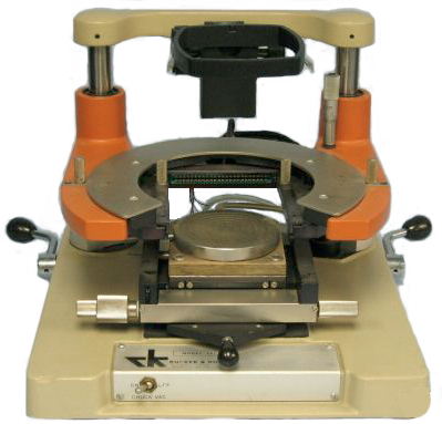


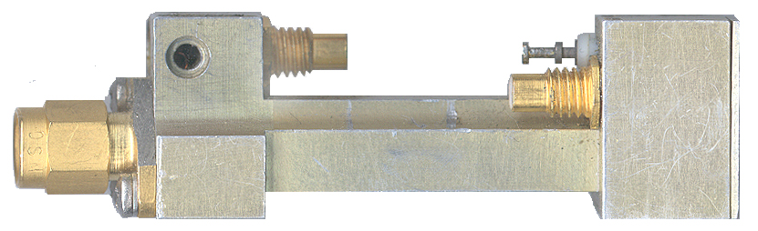 Another version was the Switched Limiter
Detector where the limiter DC return was brought out on a
connector. That way you could apply a bias to the limiter
diodes turning them on as PIN switches. This allows the
detection of a CW signal. This is a prototype unit.
An earlier version applied the limiter diode bias from the back
end of the module, but that did not work because there was cross
talk between the diode drive signal and the detector output.
Another version was the Switched Limiter
Detector where the limiter DC return was brought out on a
connector. That way you could apply a bias to the limiter
diodes turning them on as PIN switches. This allows the
detection of a CW signal. This is a prototype unit.
An earlier version applied the limiter diode bias from the back
end of the module, but that did not work because there was cross
talk between the diode drive signal and the detector output. 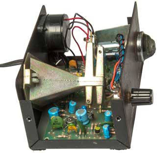
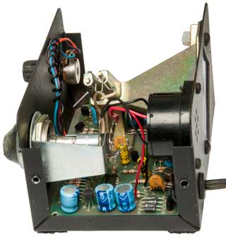

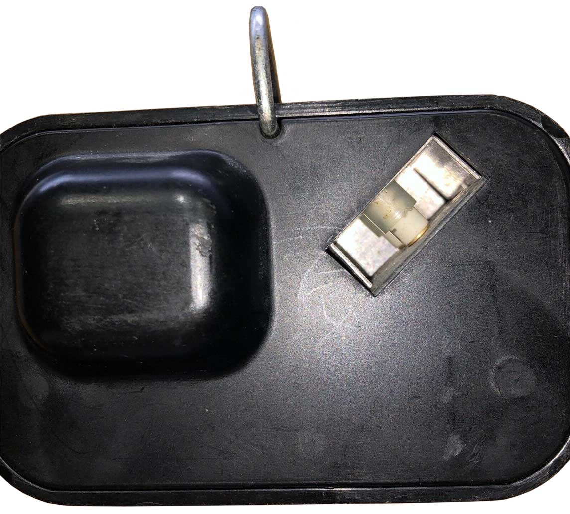
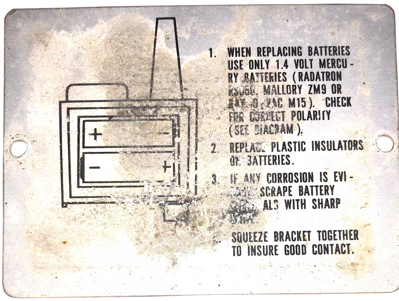

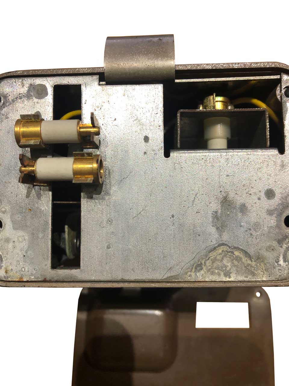
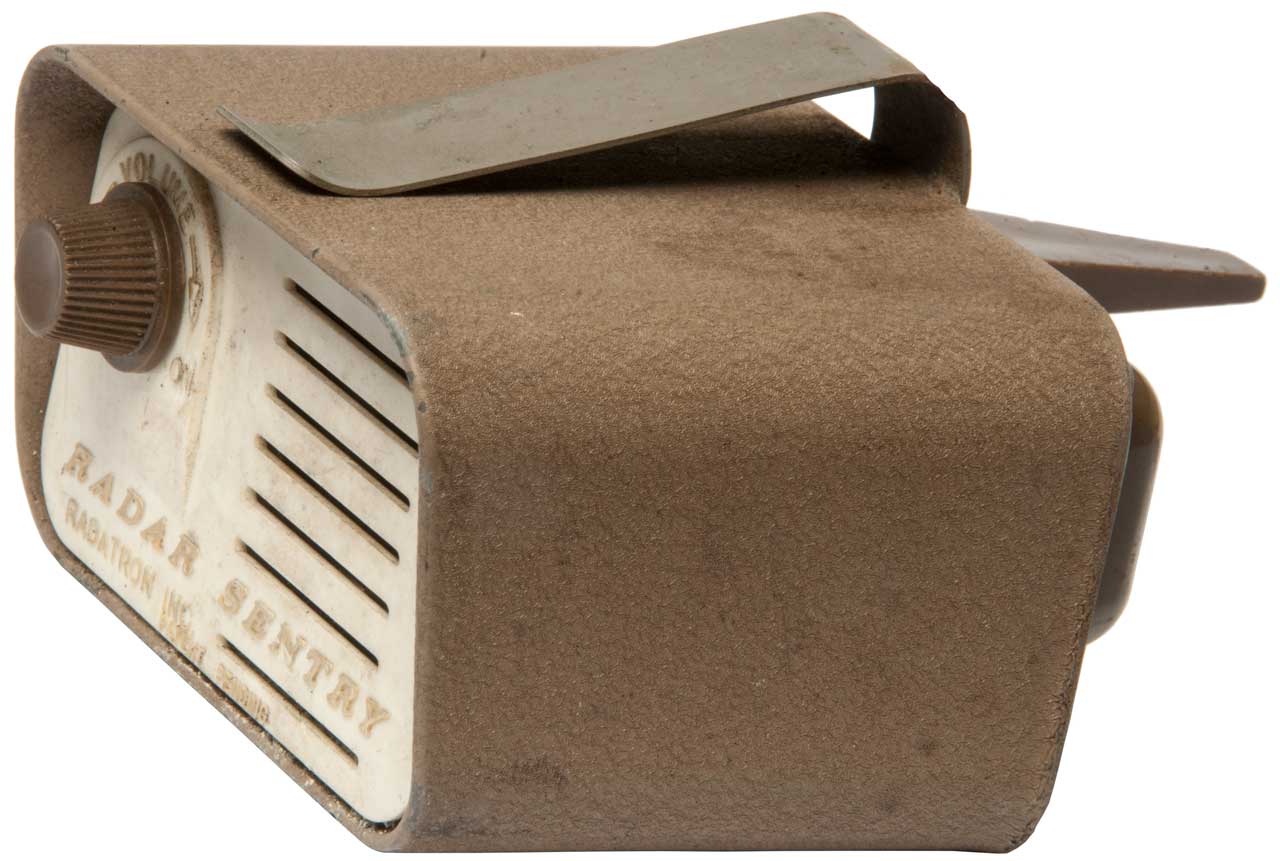
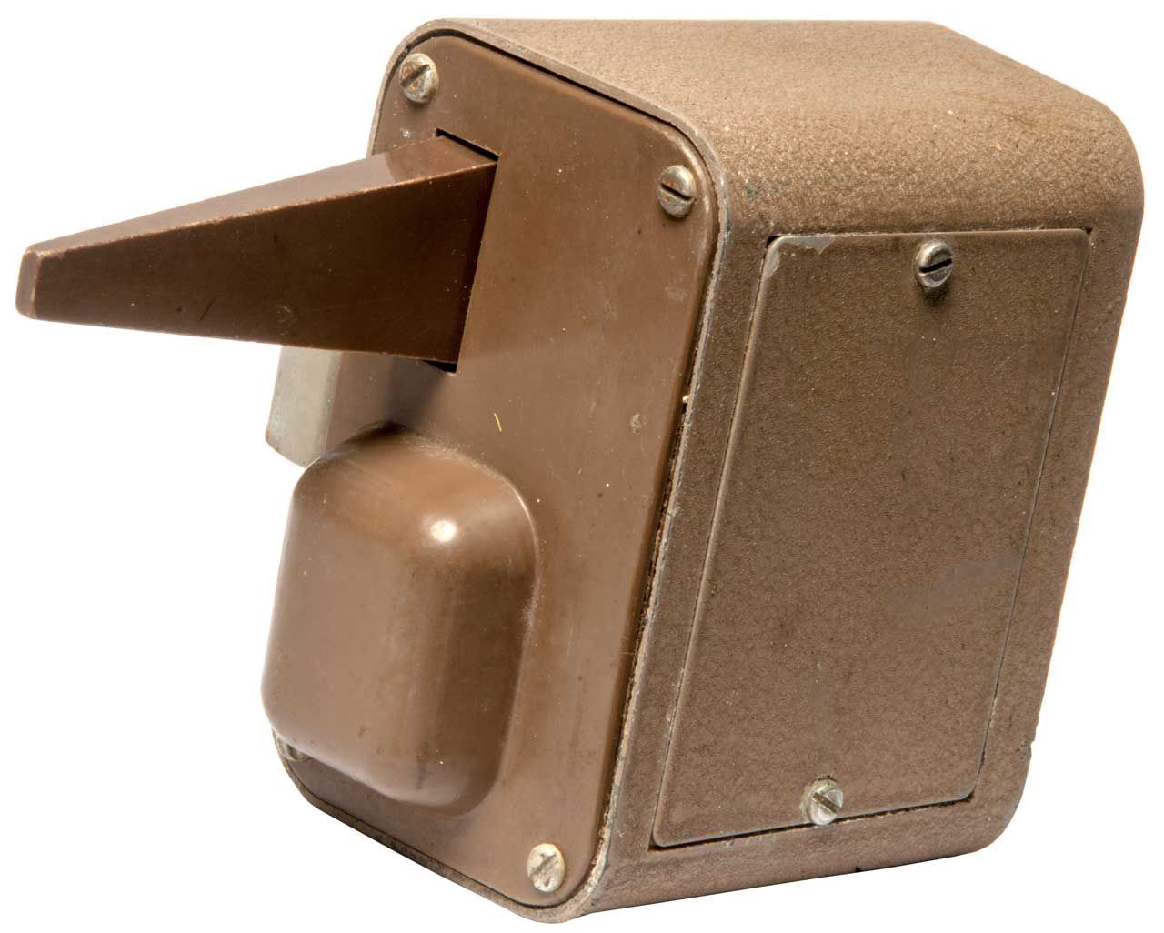
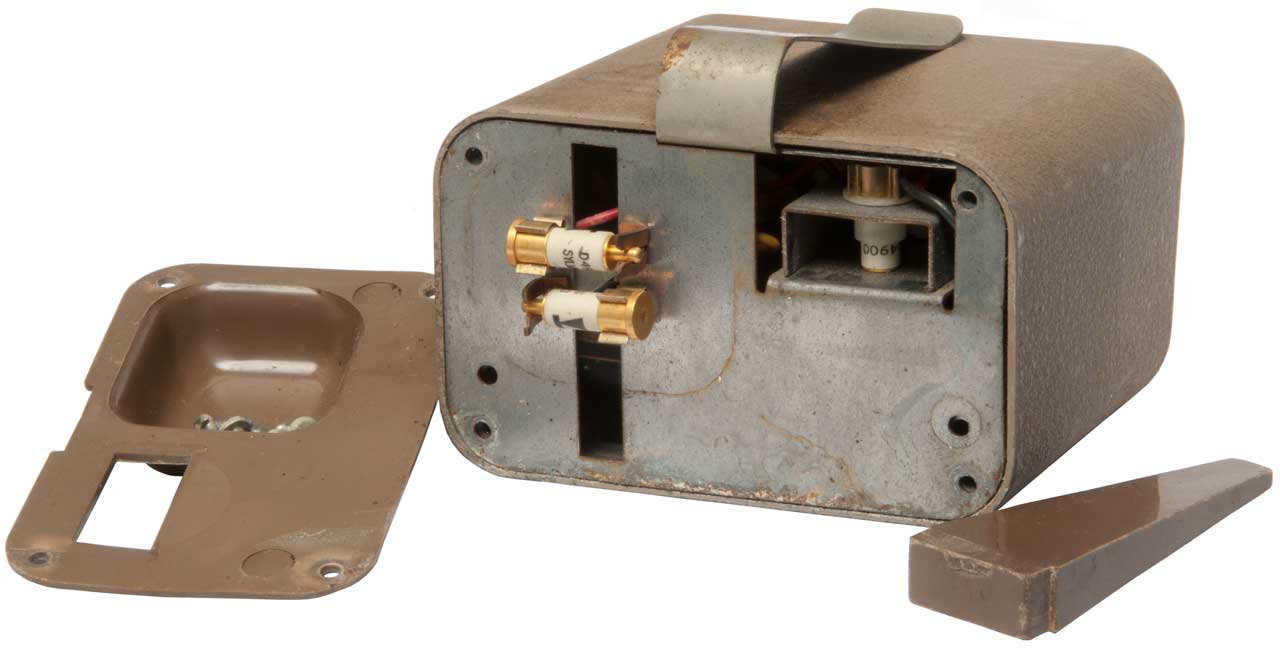
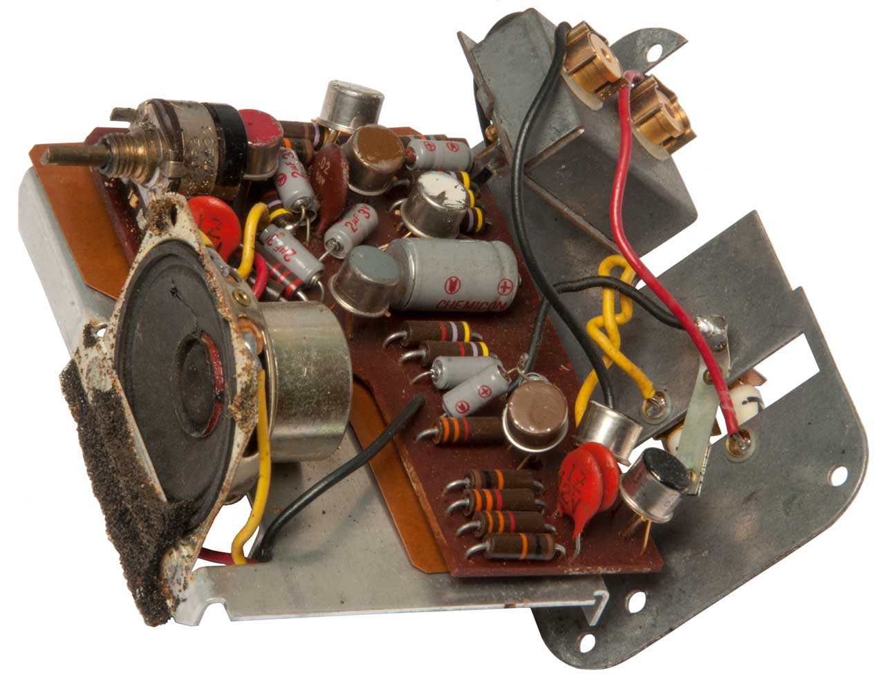
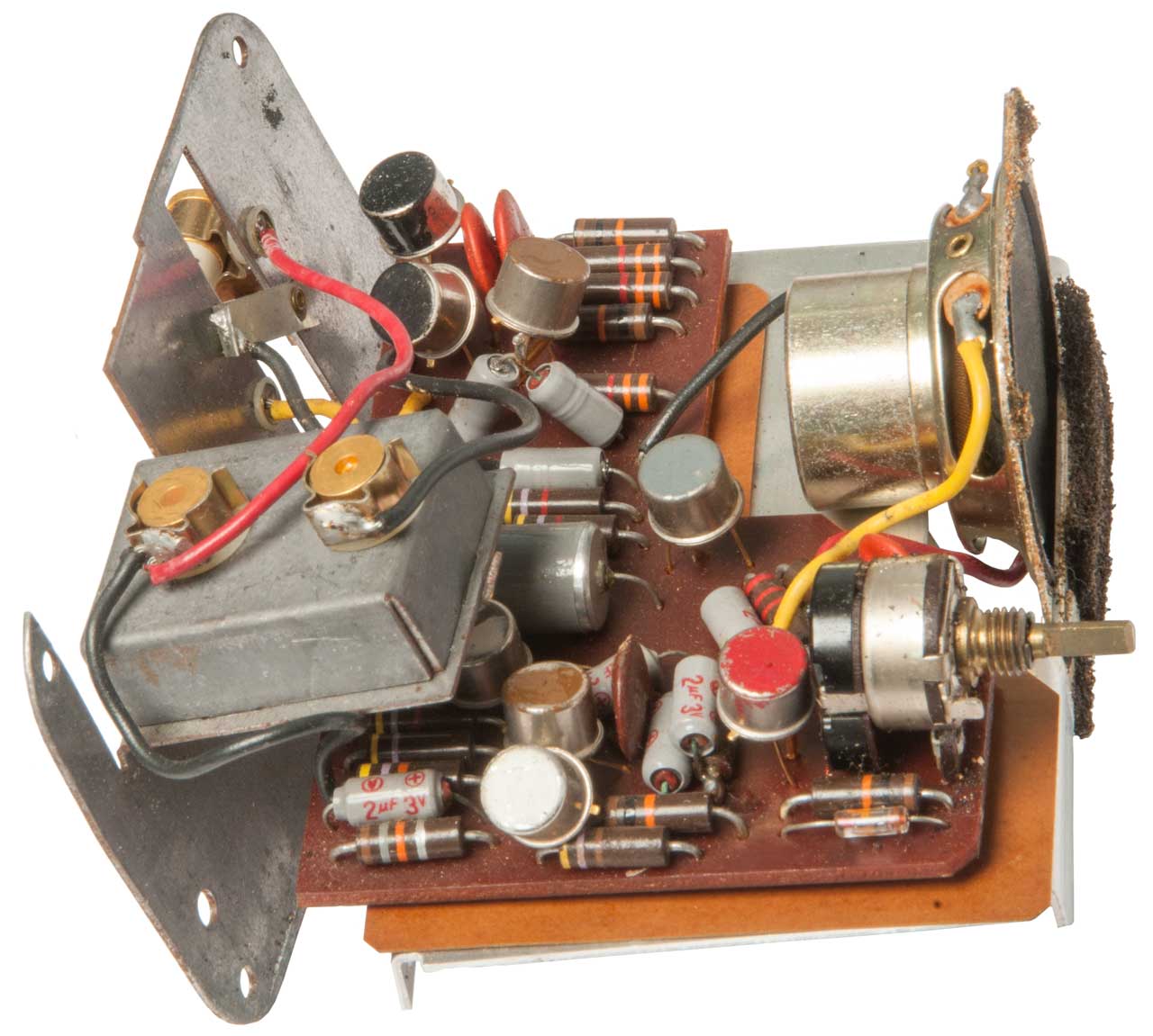
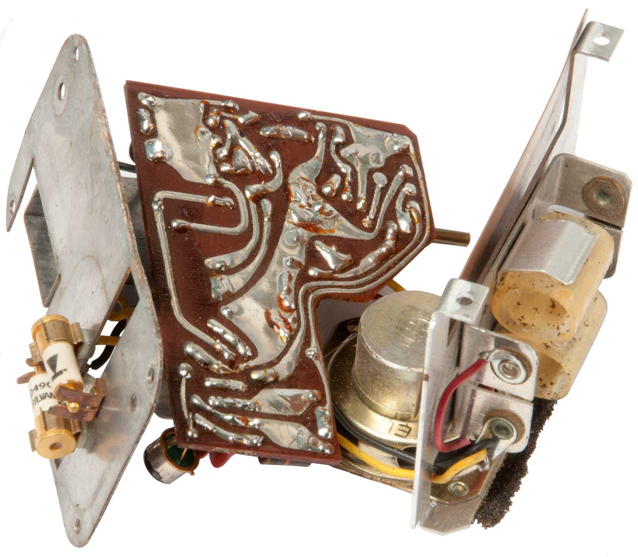
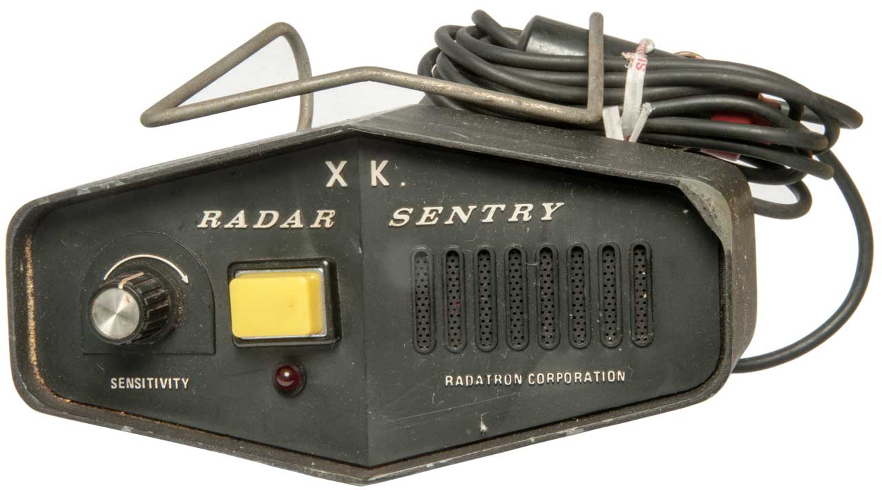

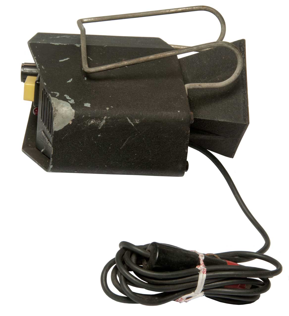
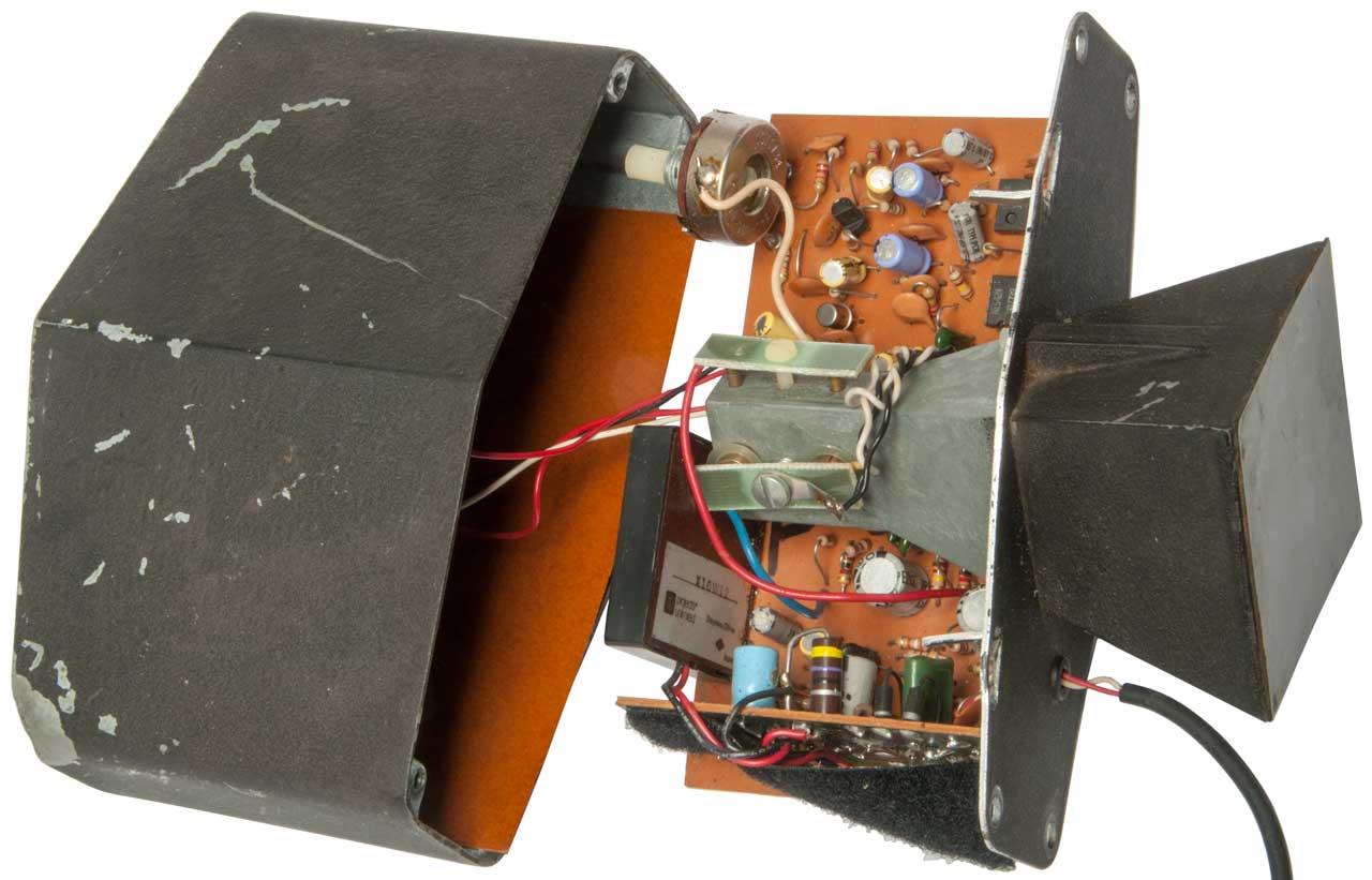
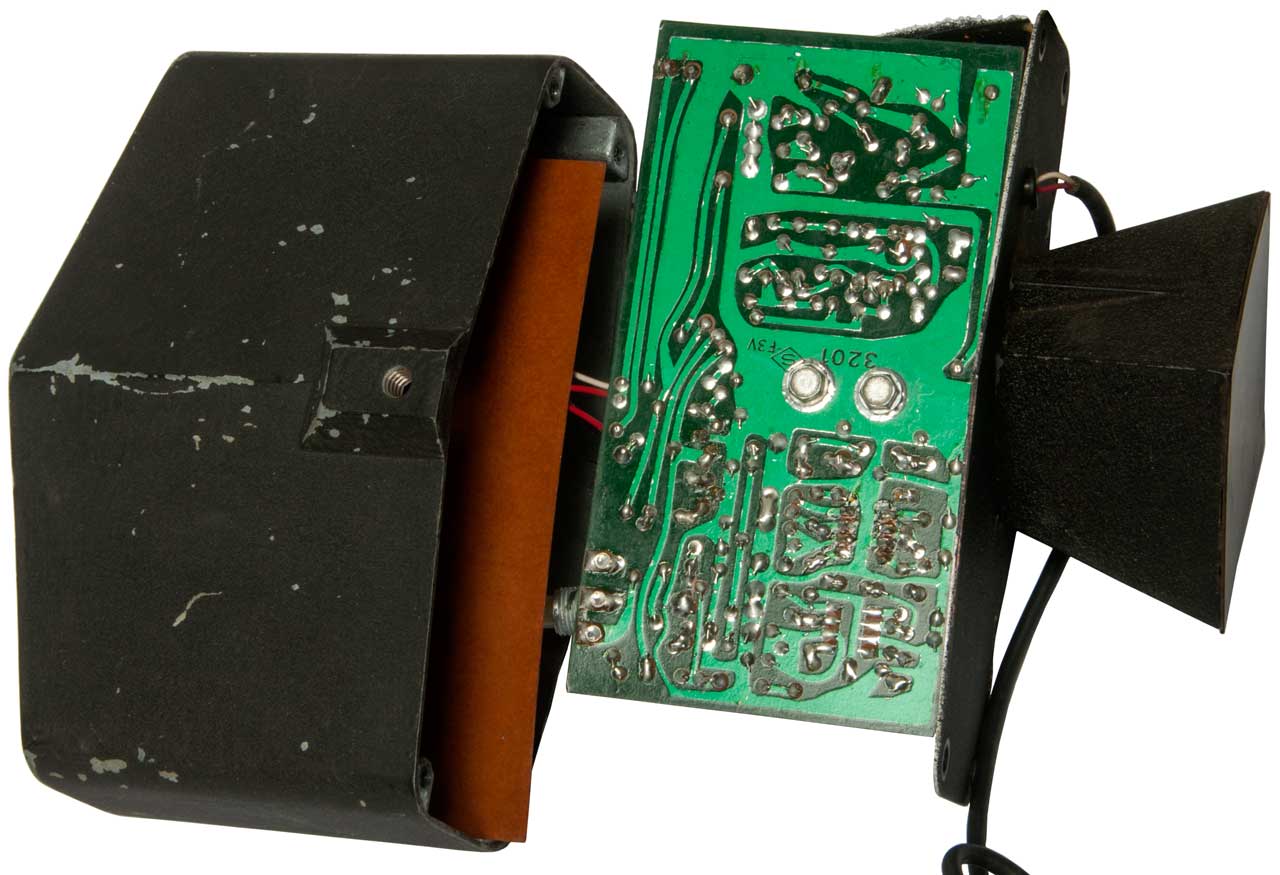
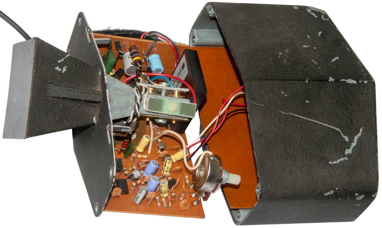
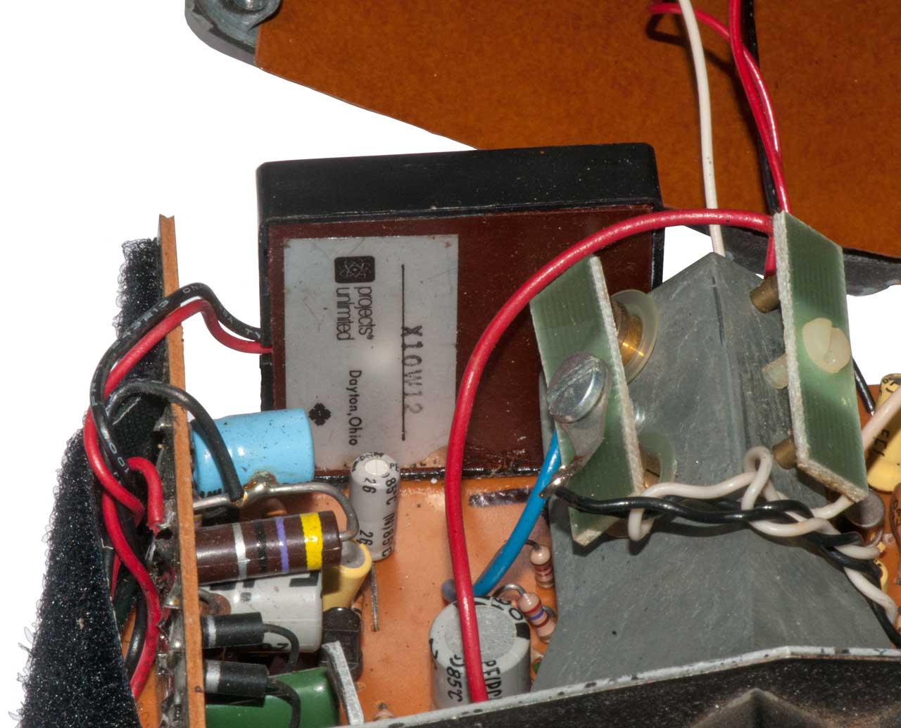
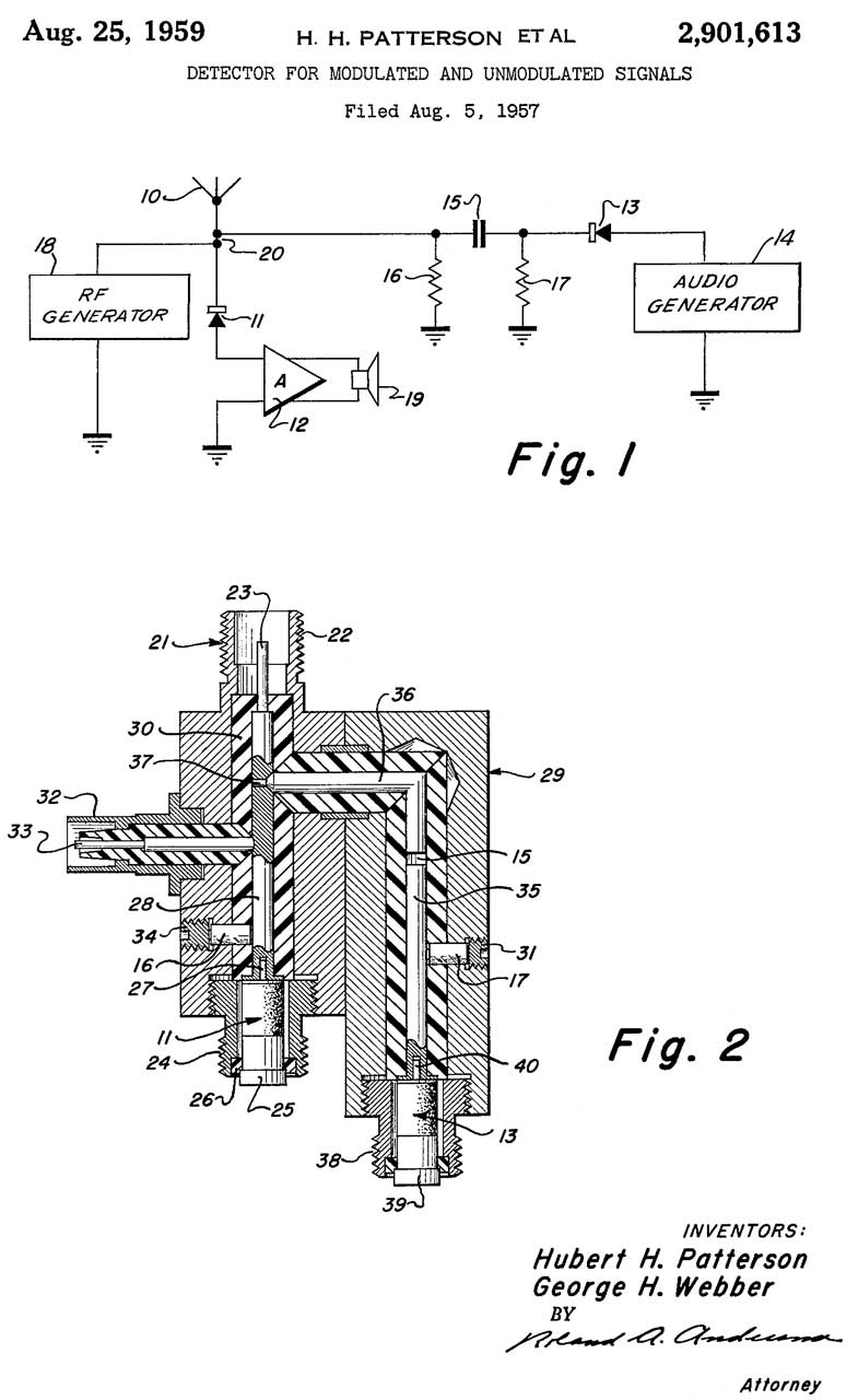
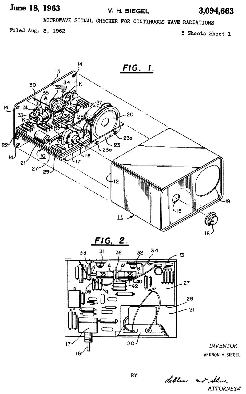
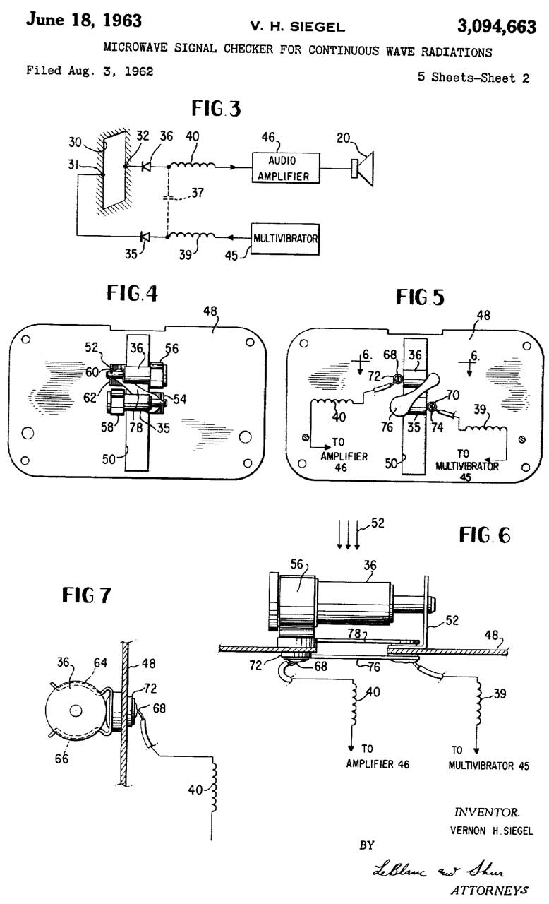
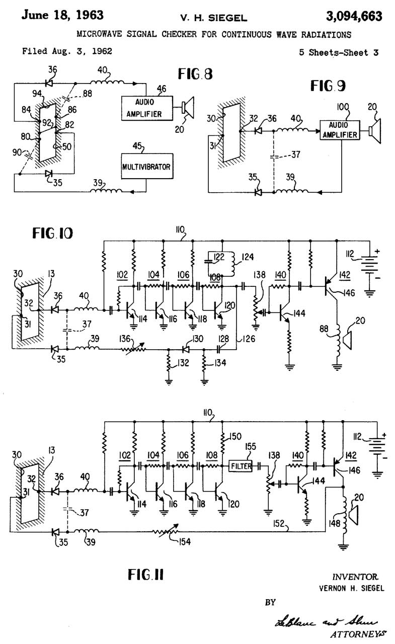
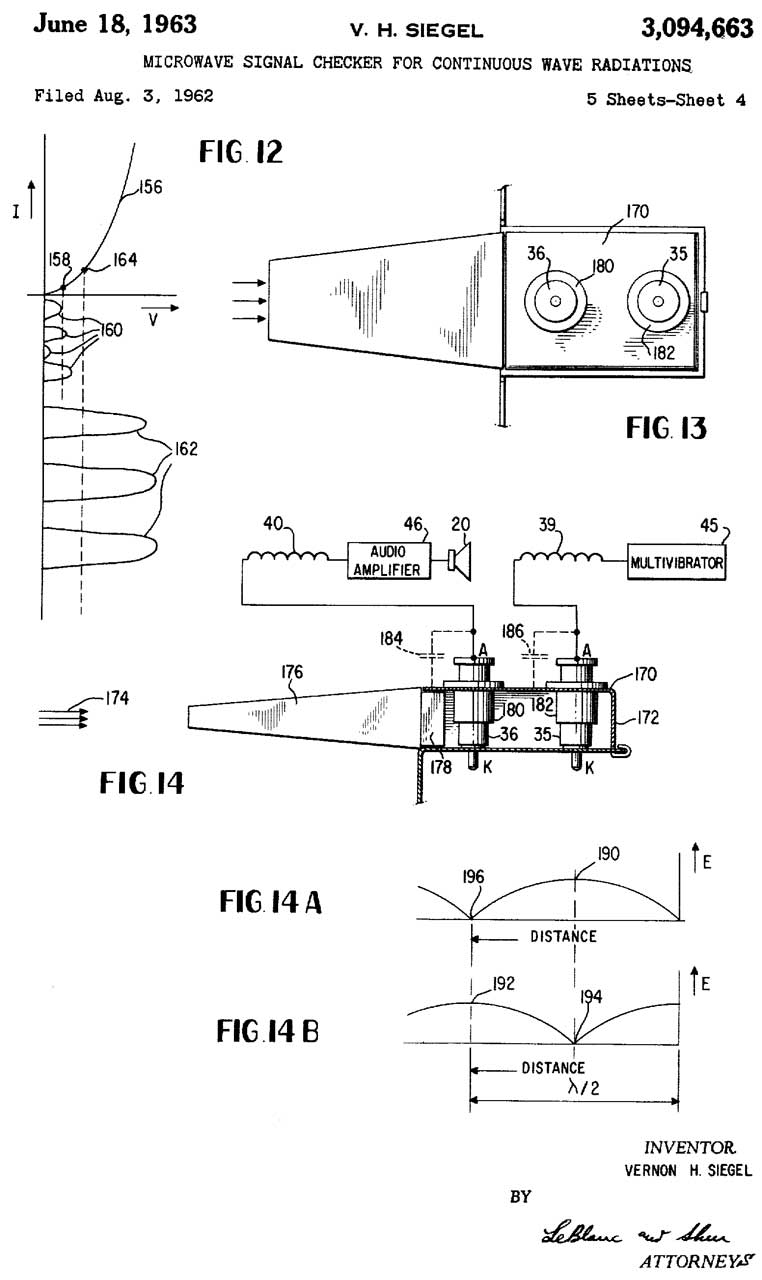
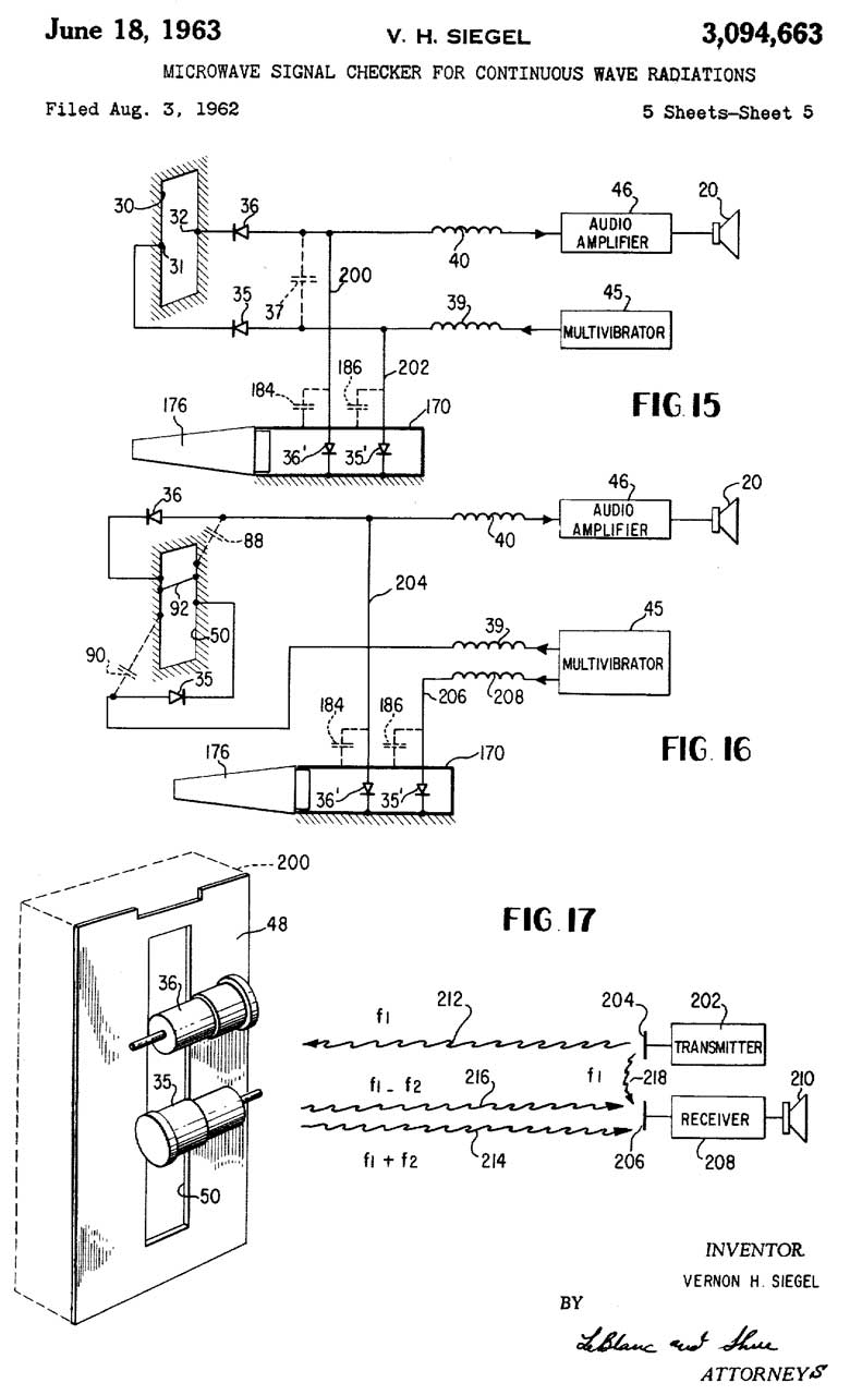
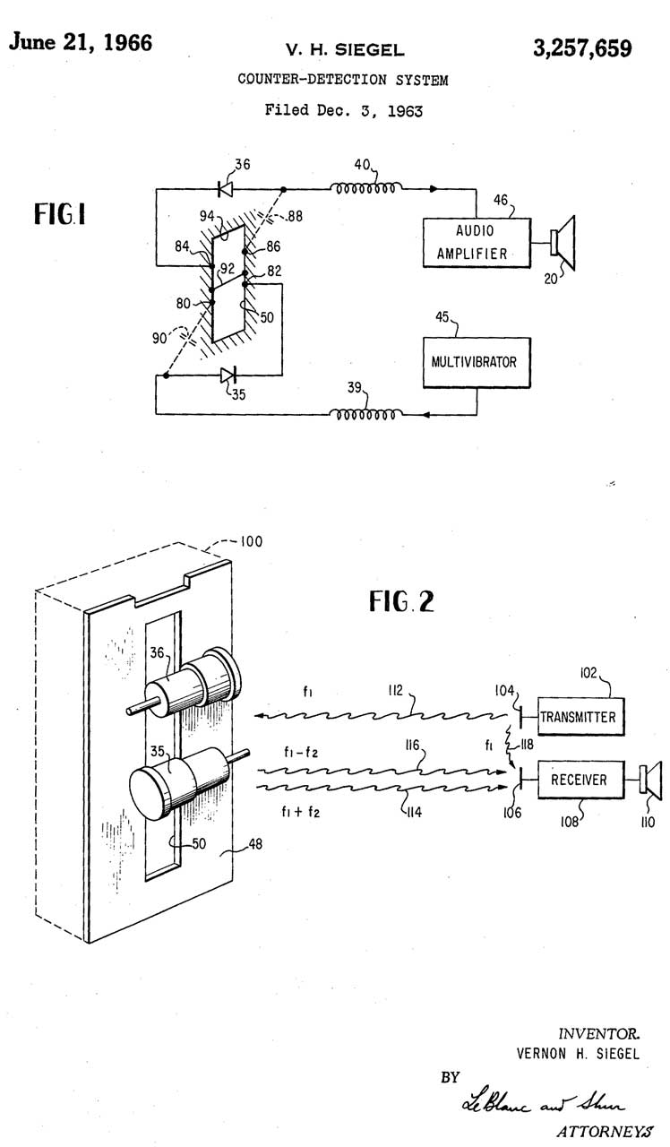
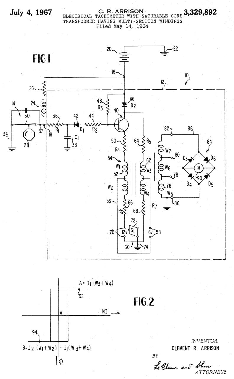

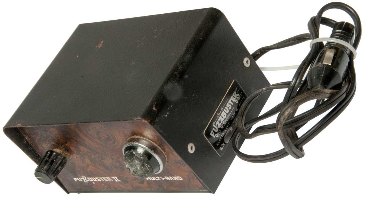
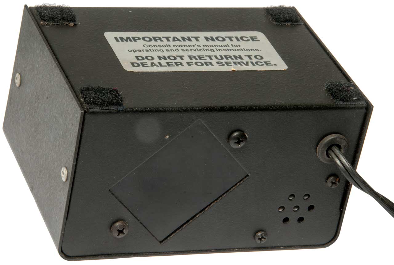

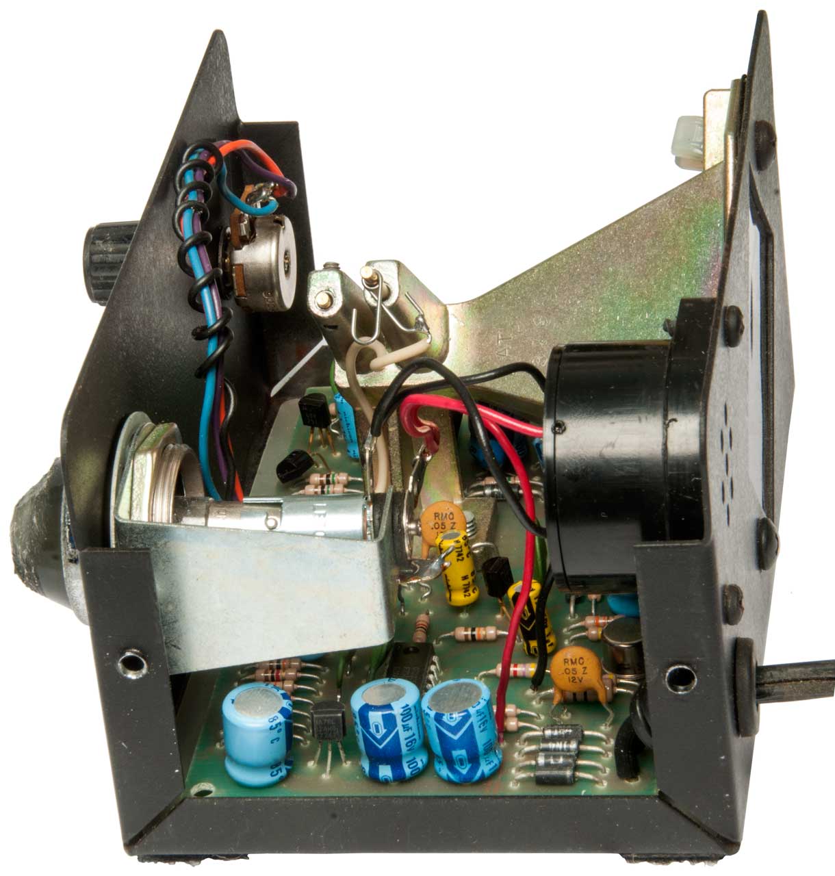


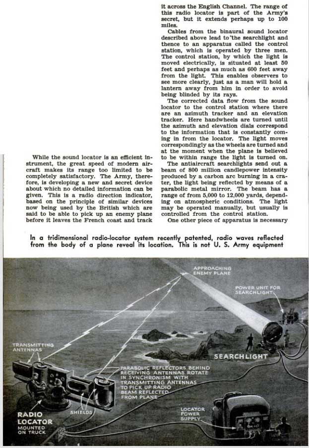
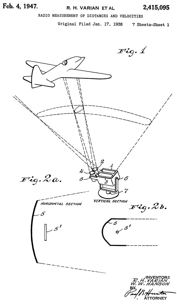


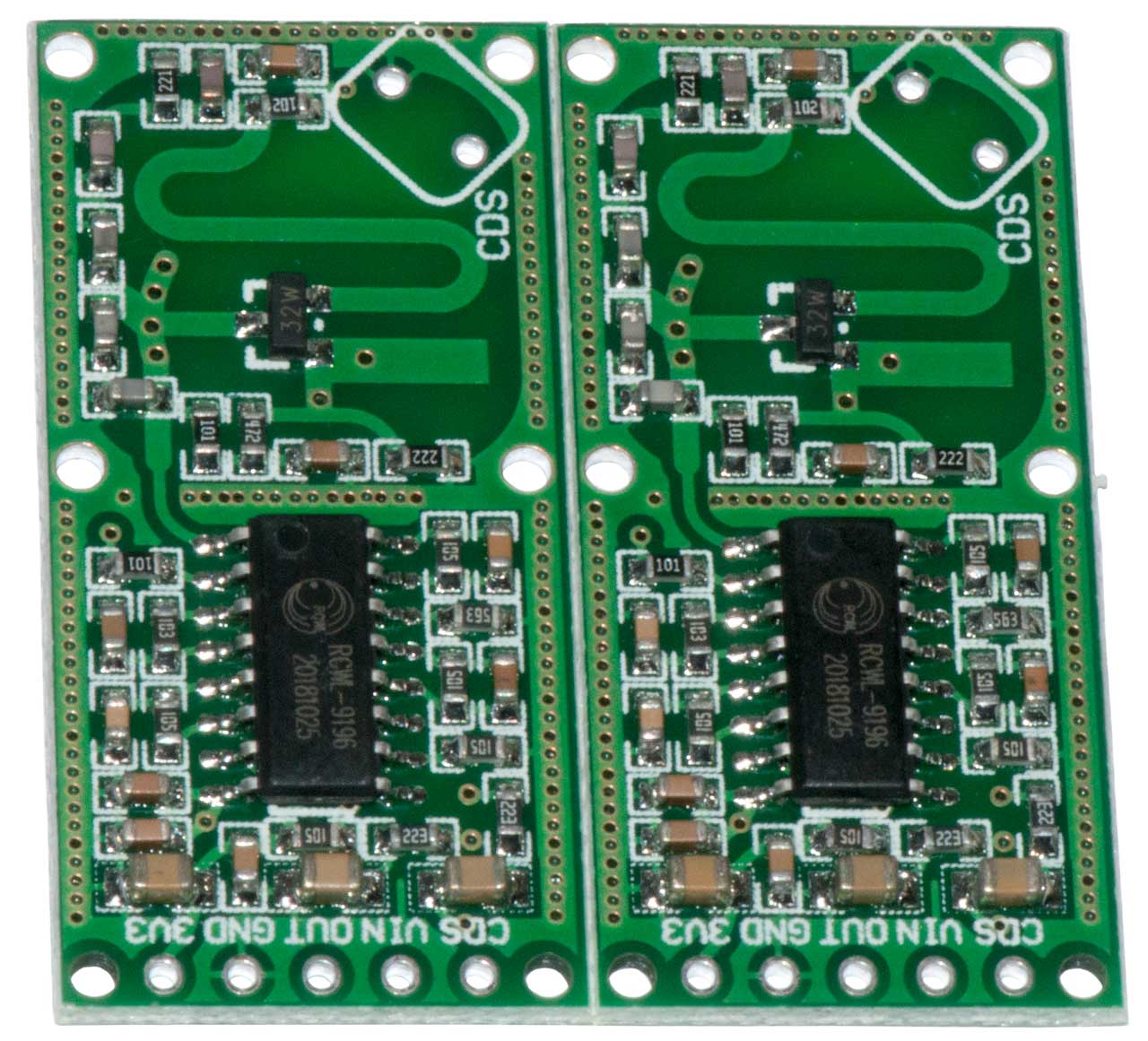
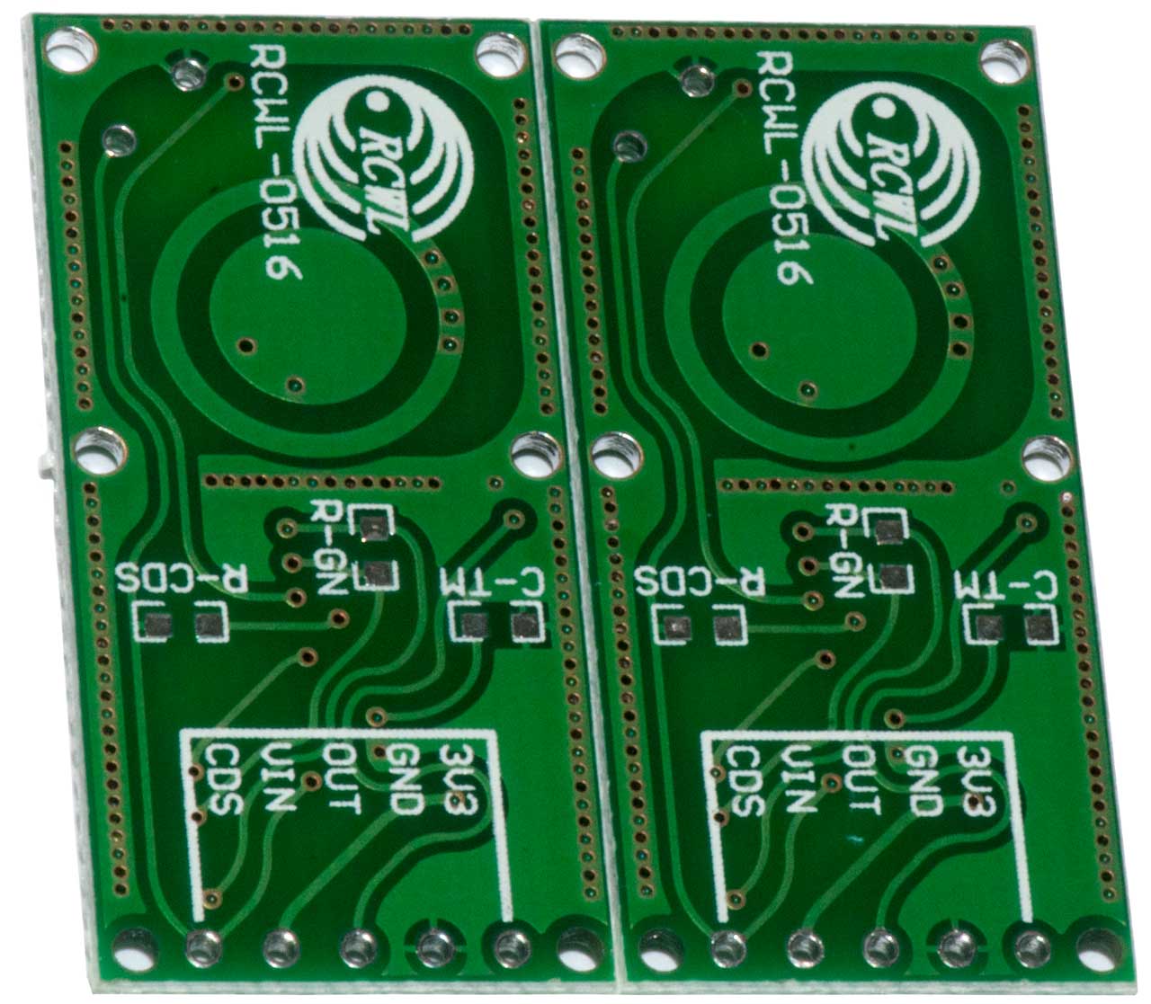
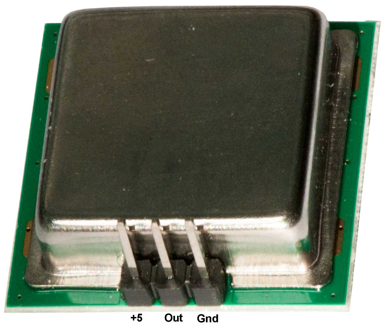
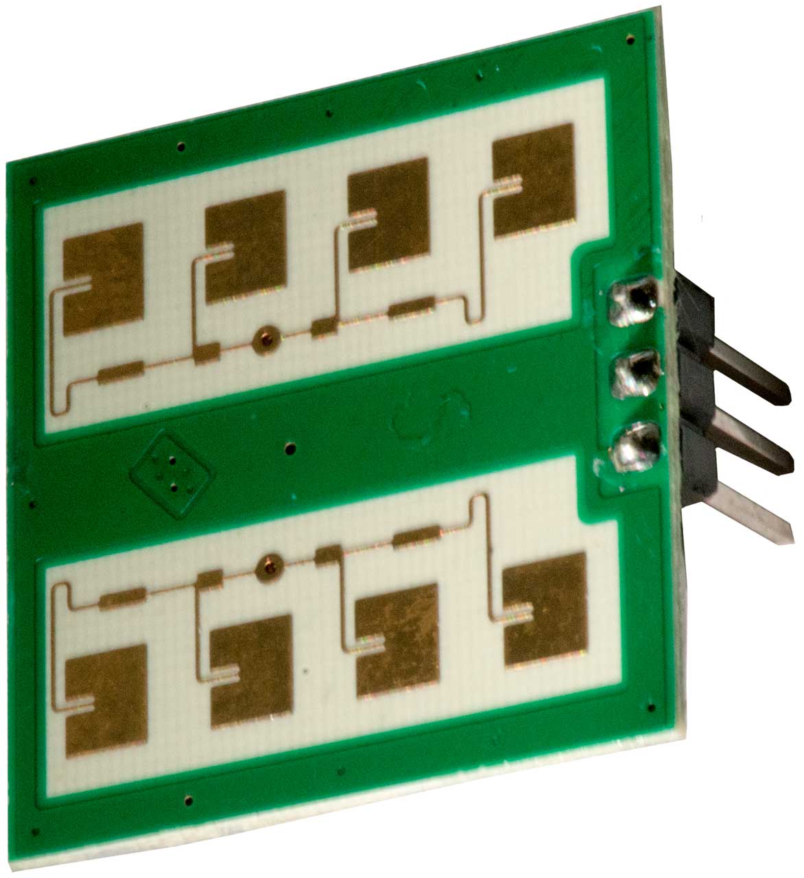
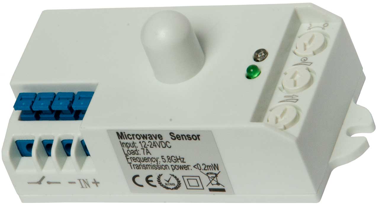

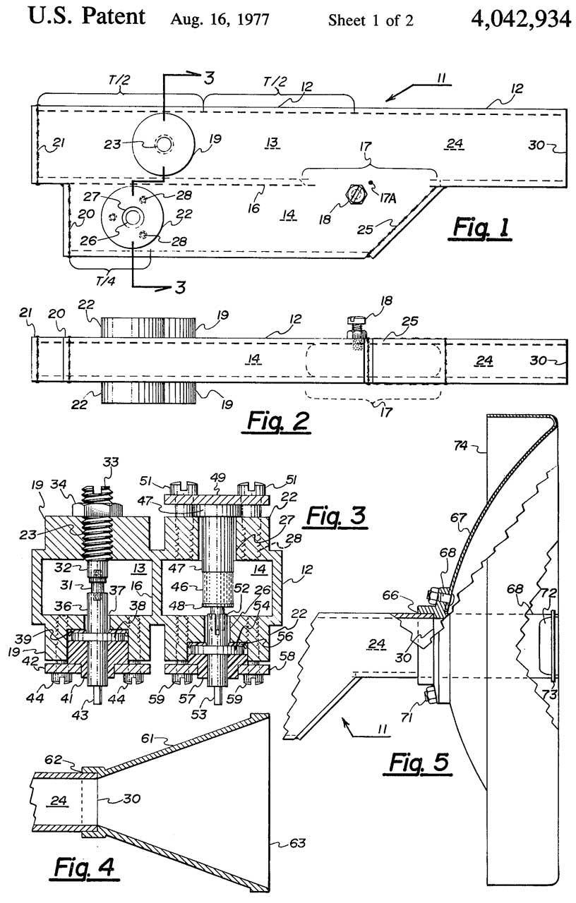
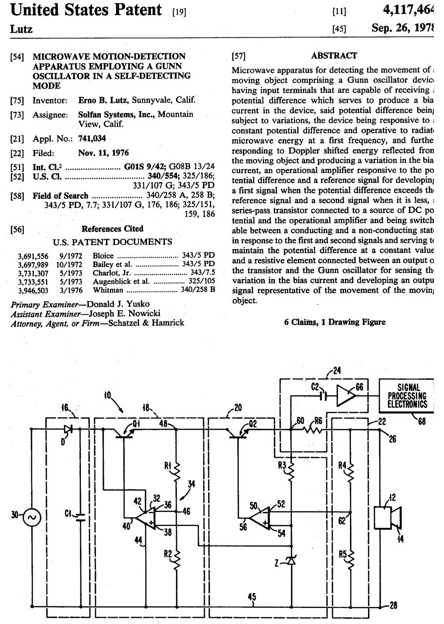

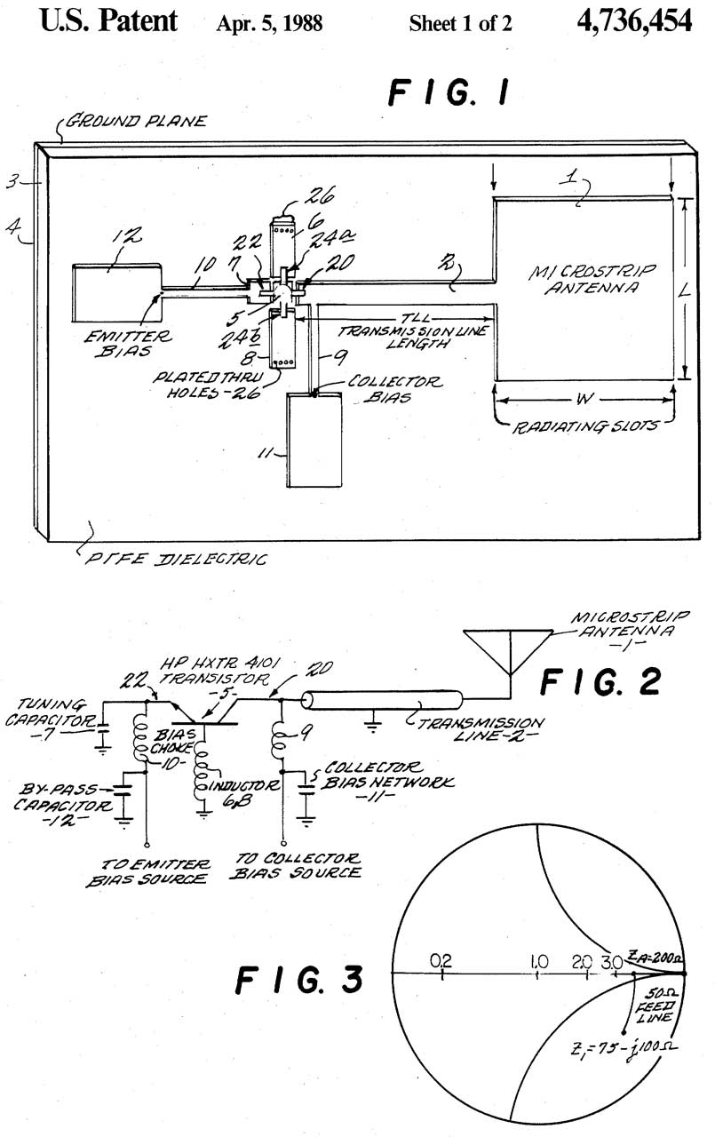


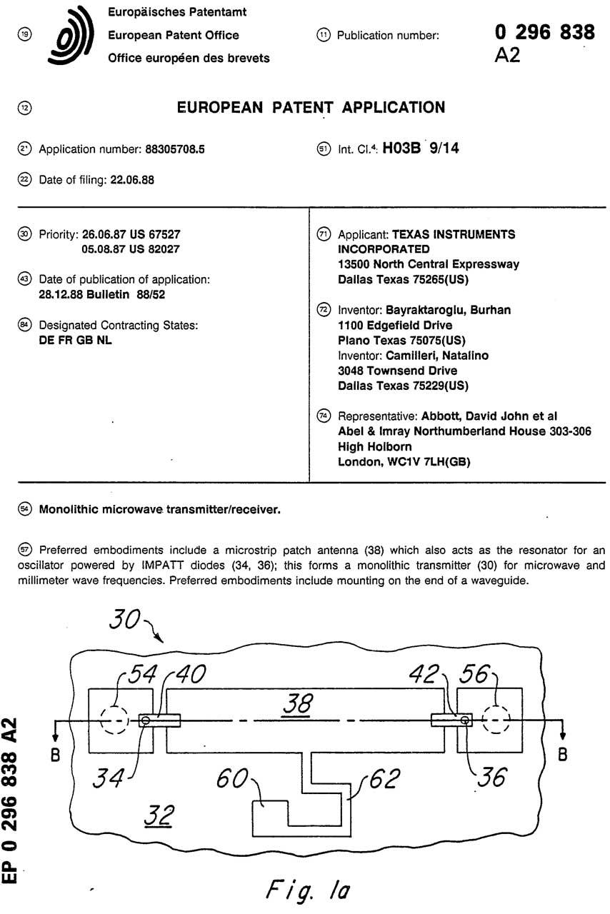
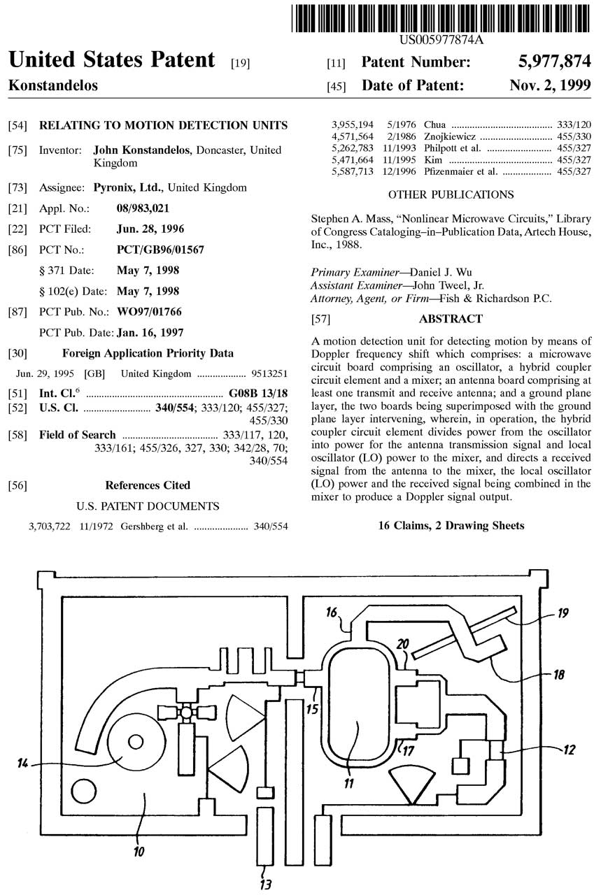
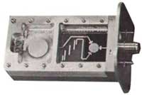
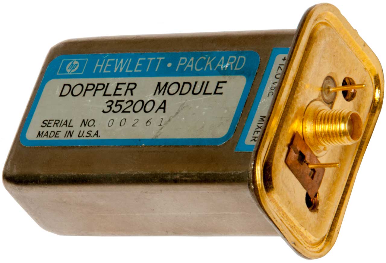


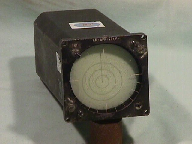
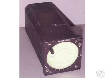
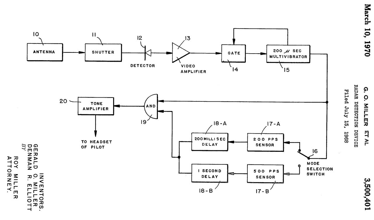

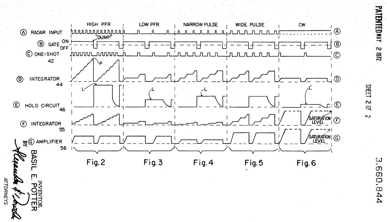
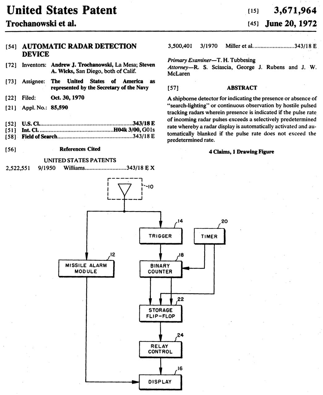
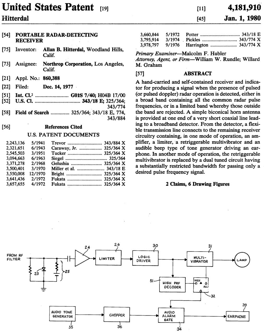
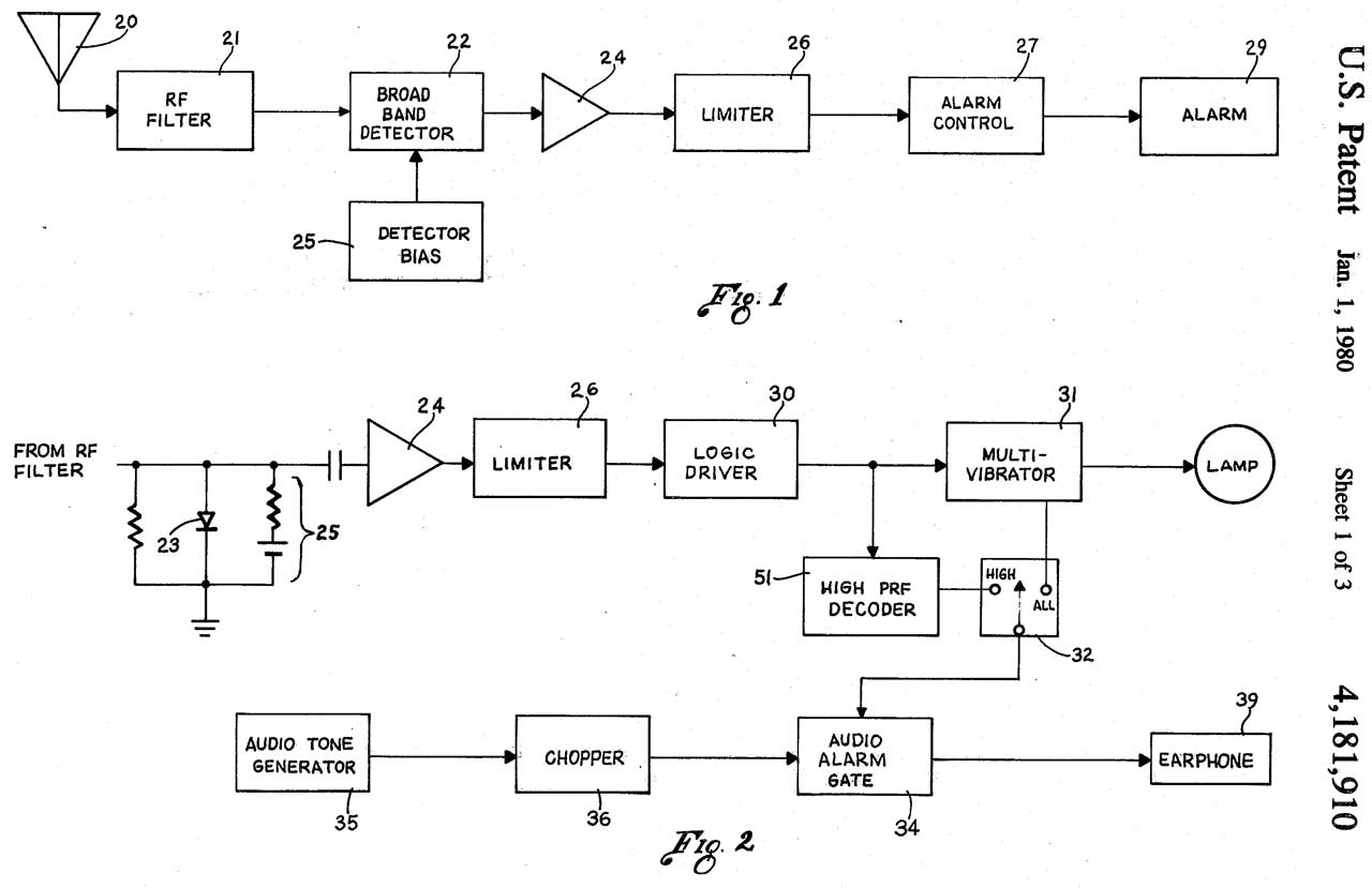
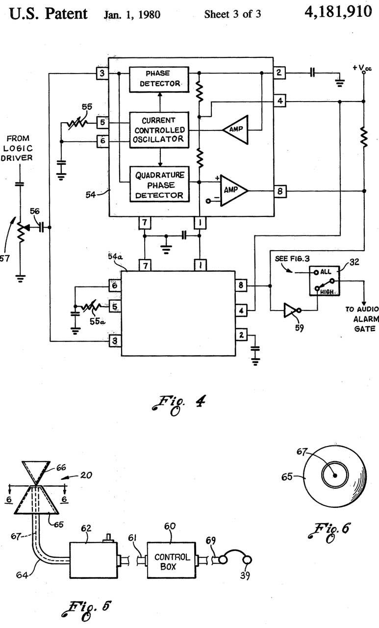
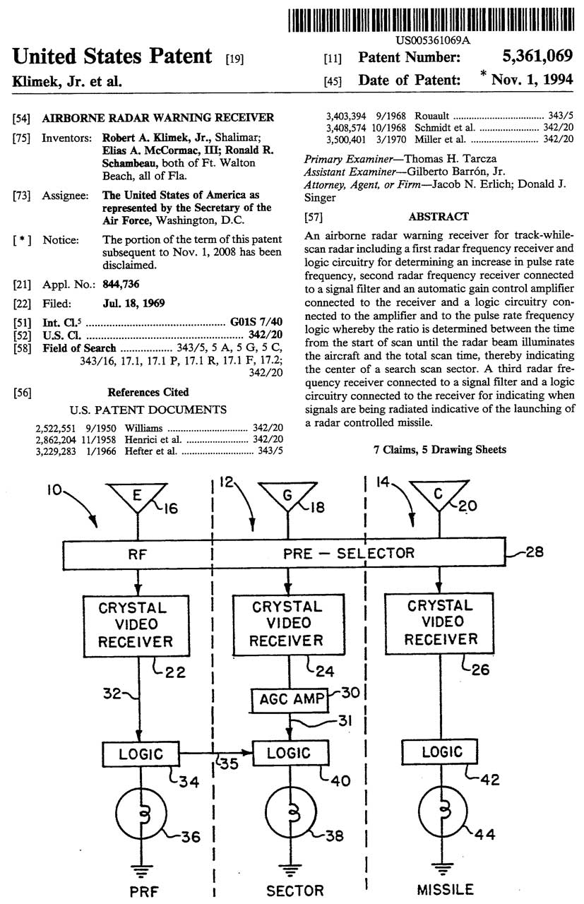


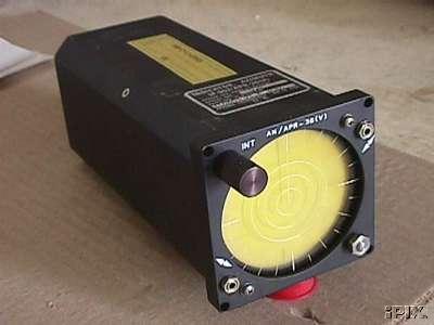
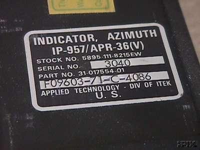


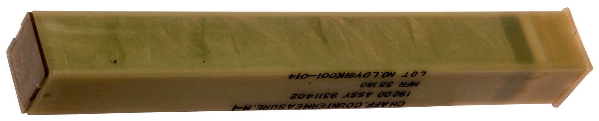
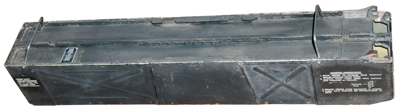

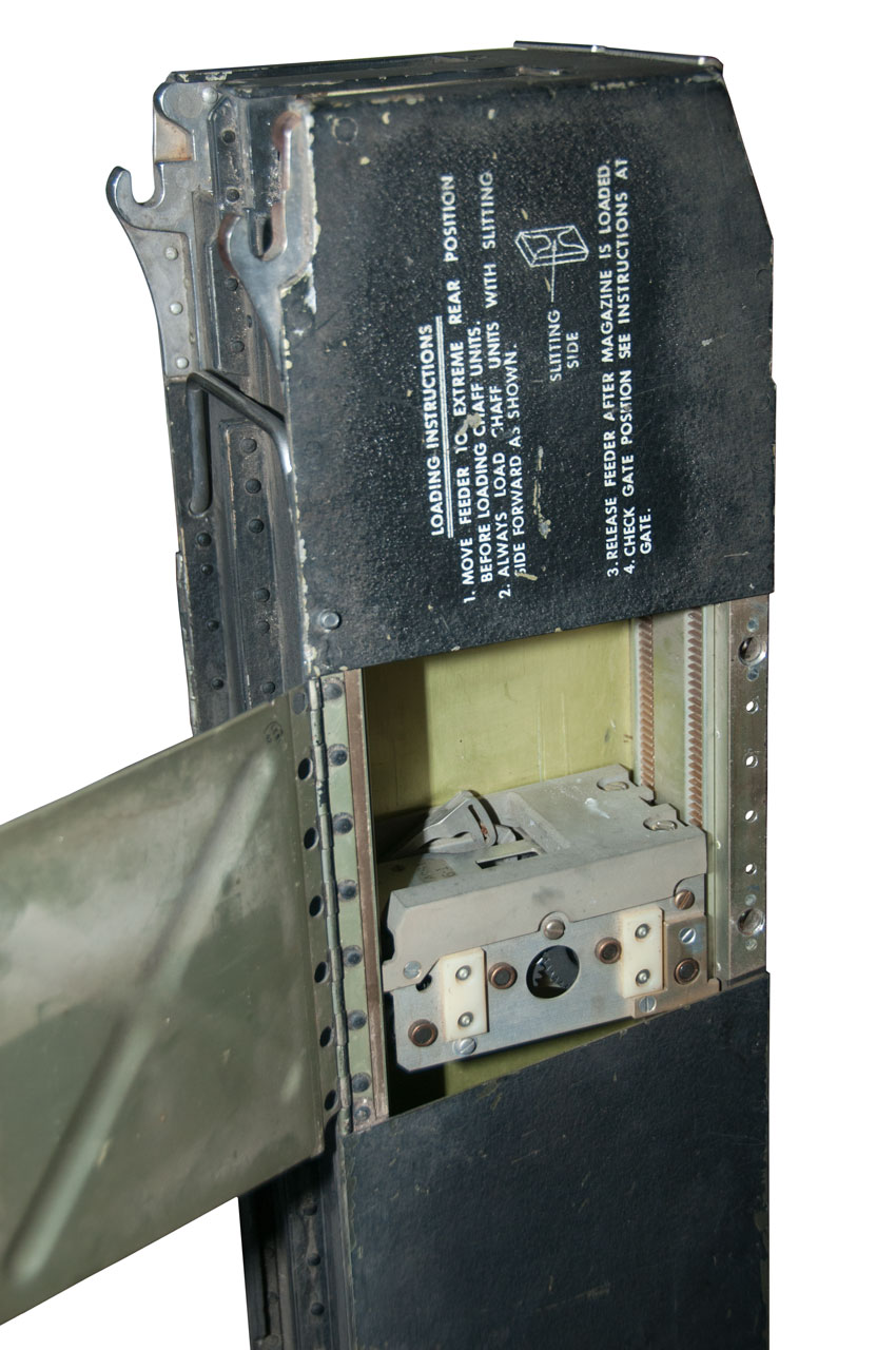

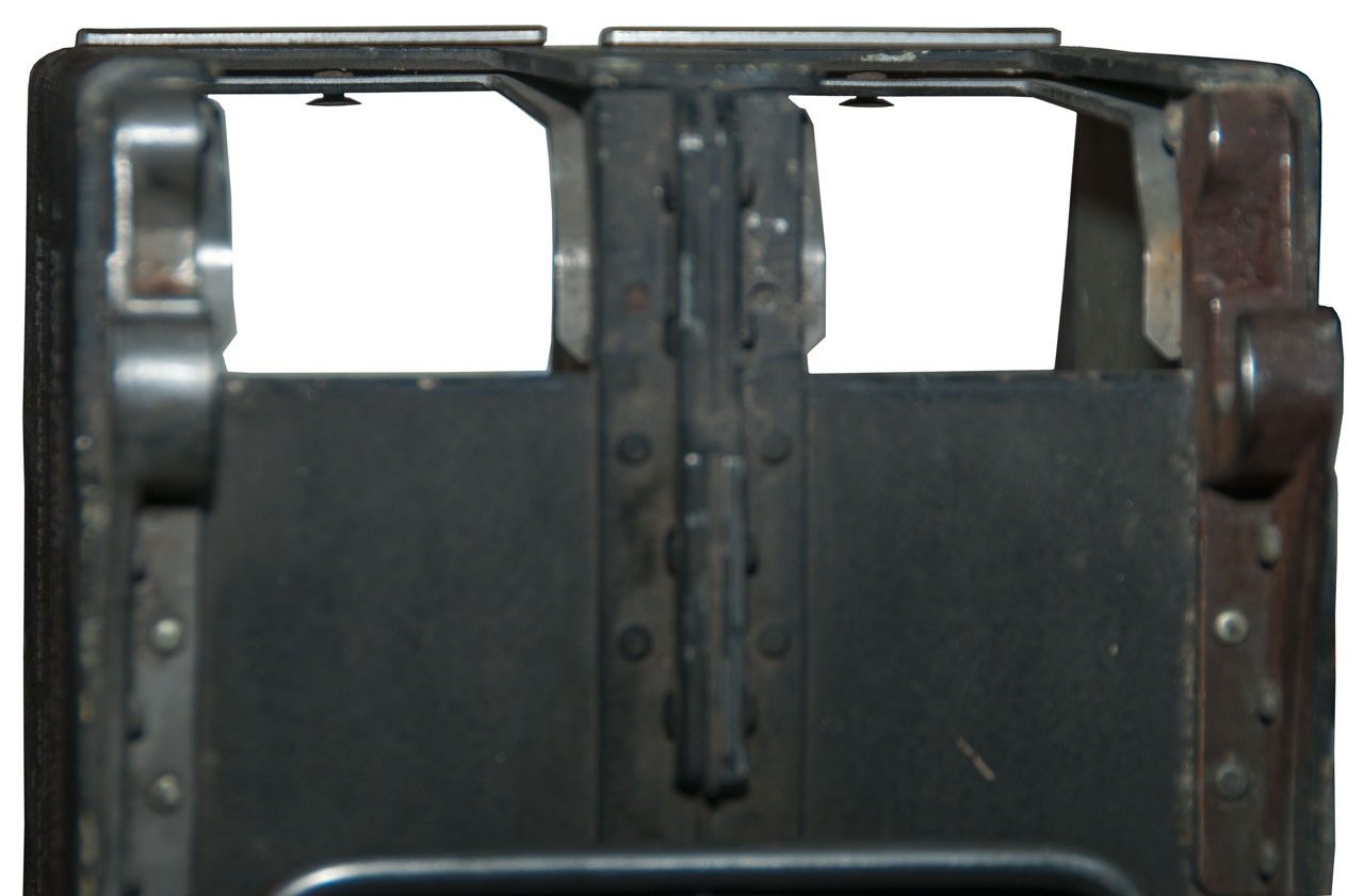
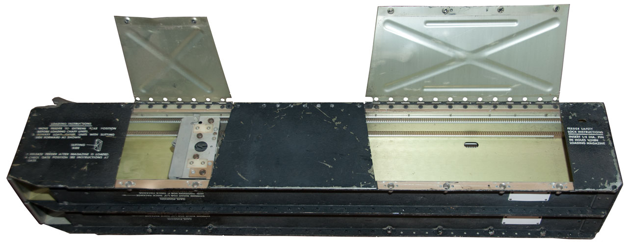
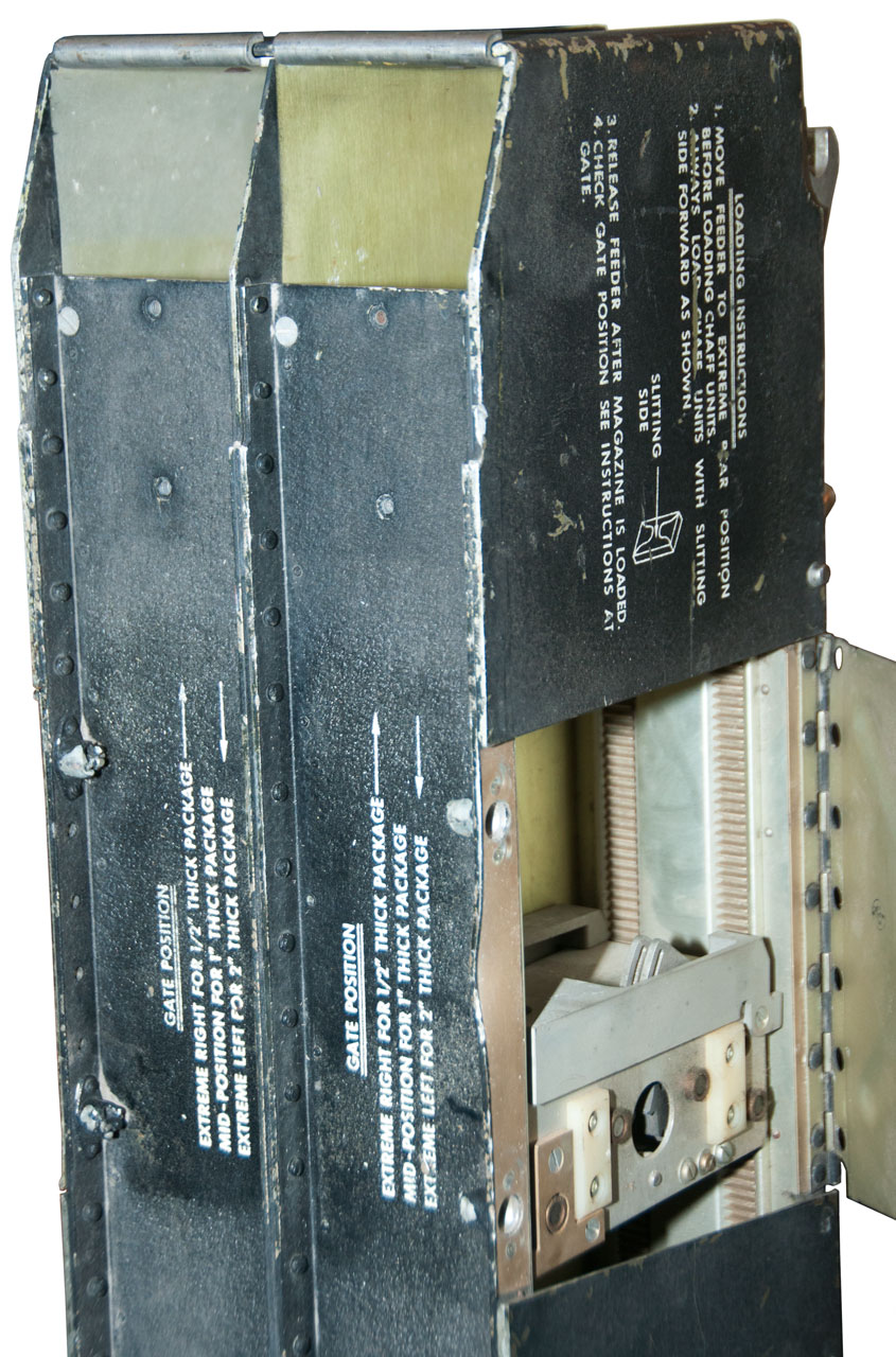

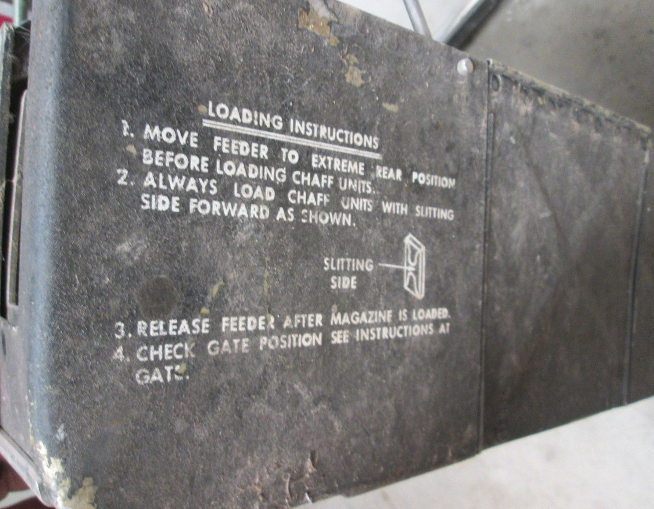
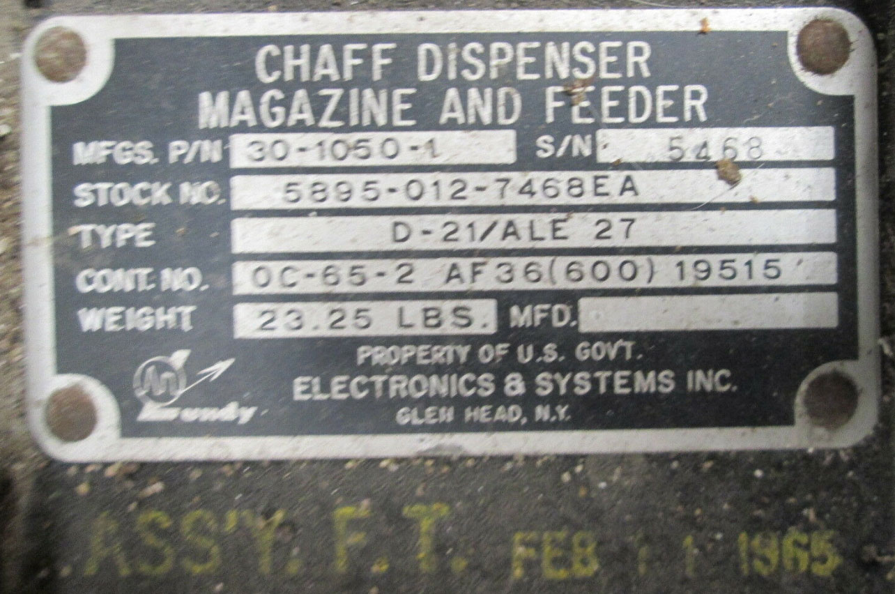
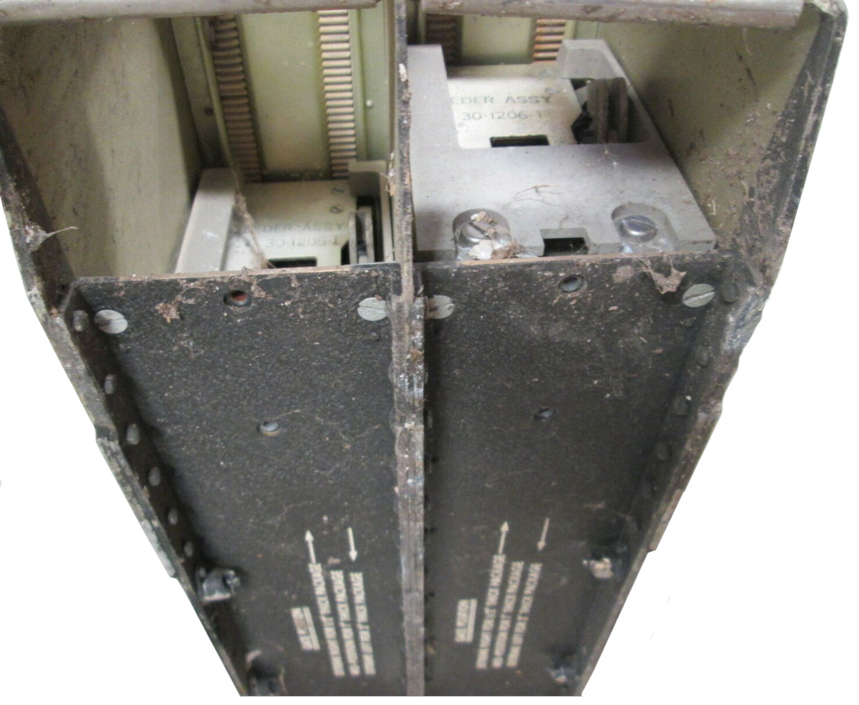
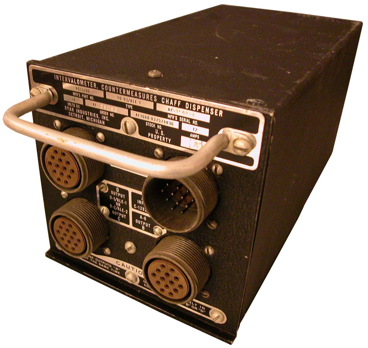
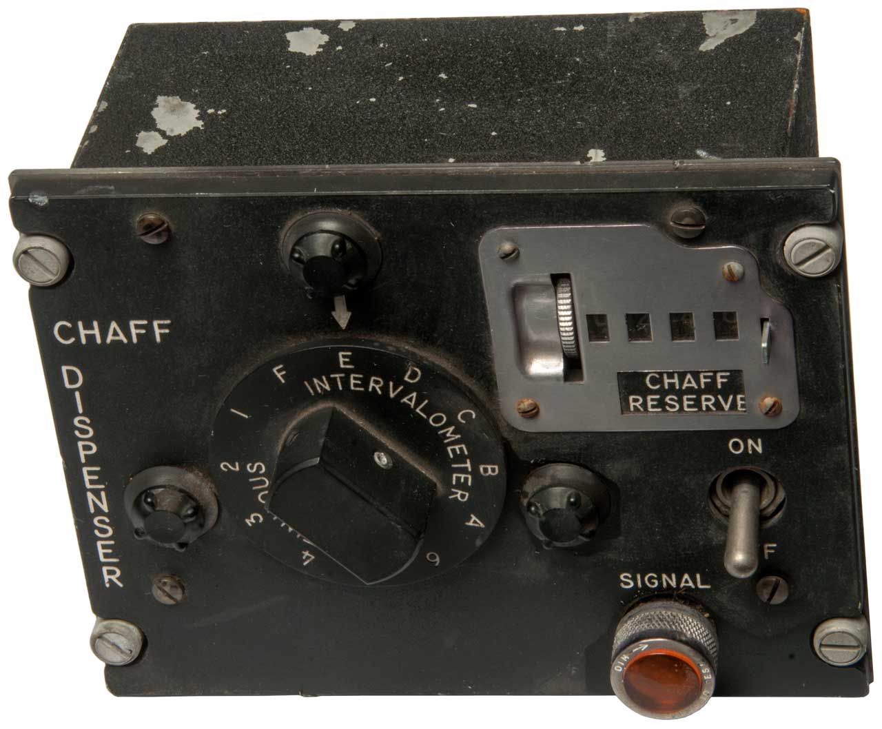
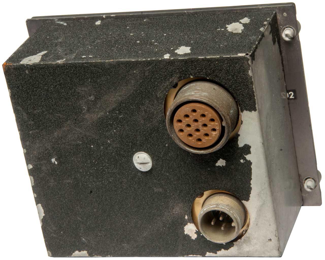


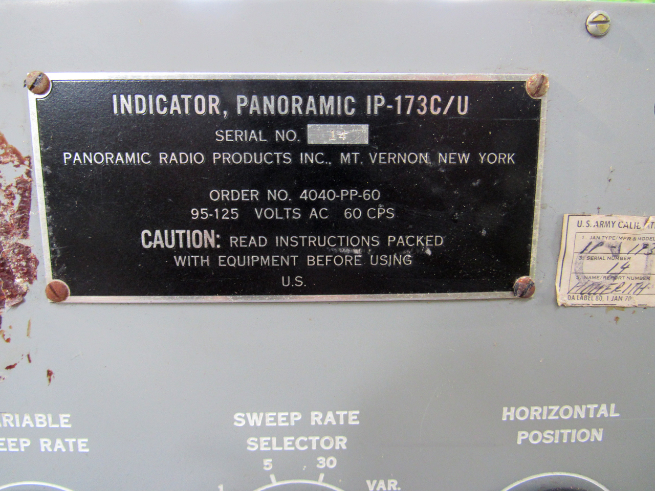
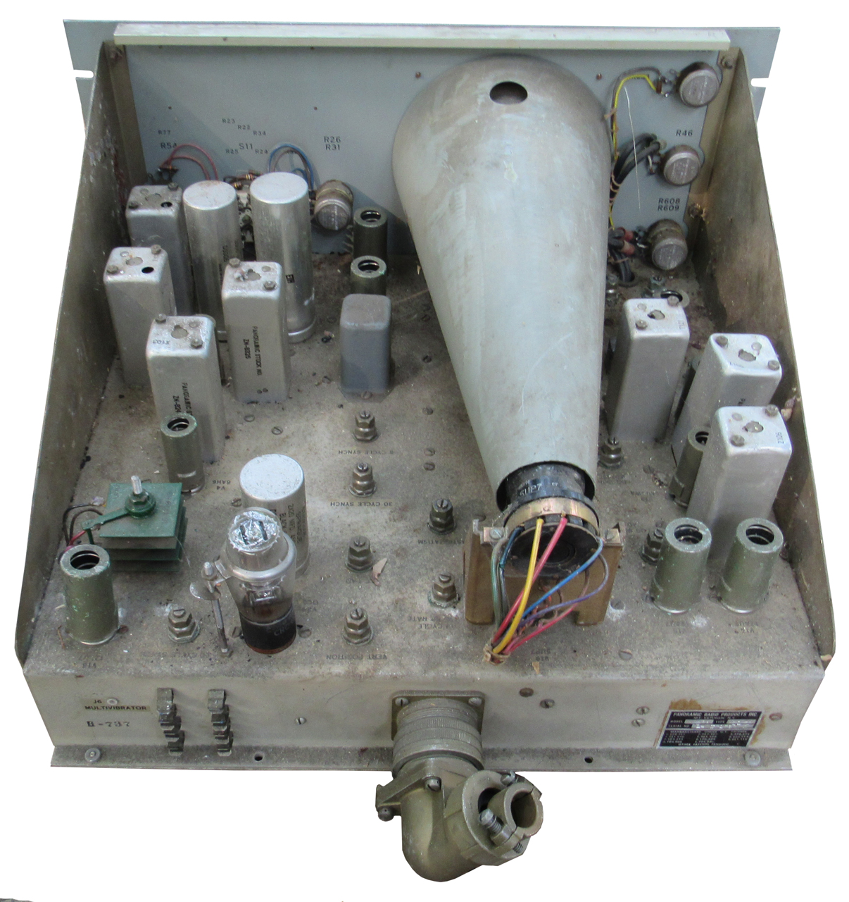

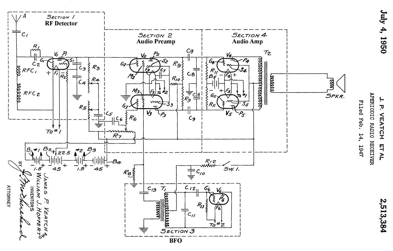
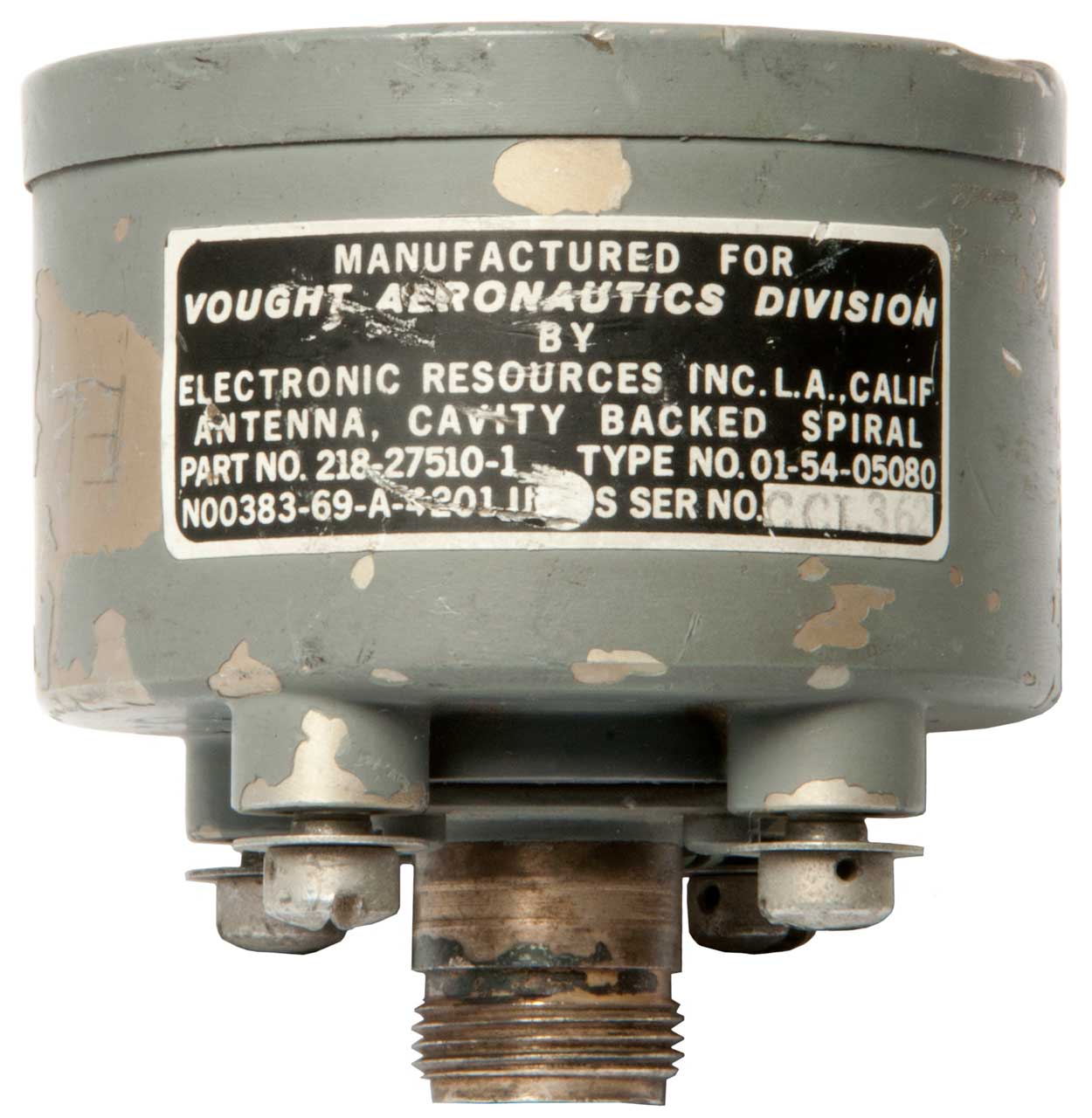


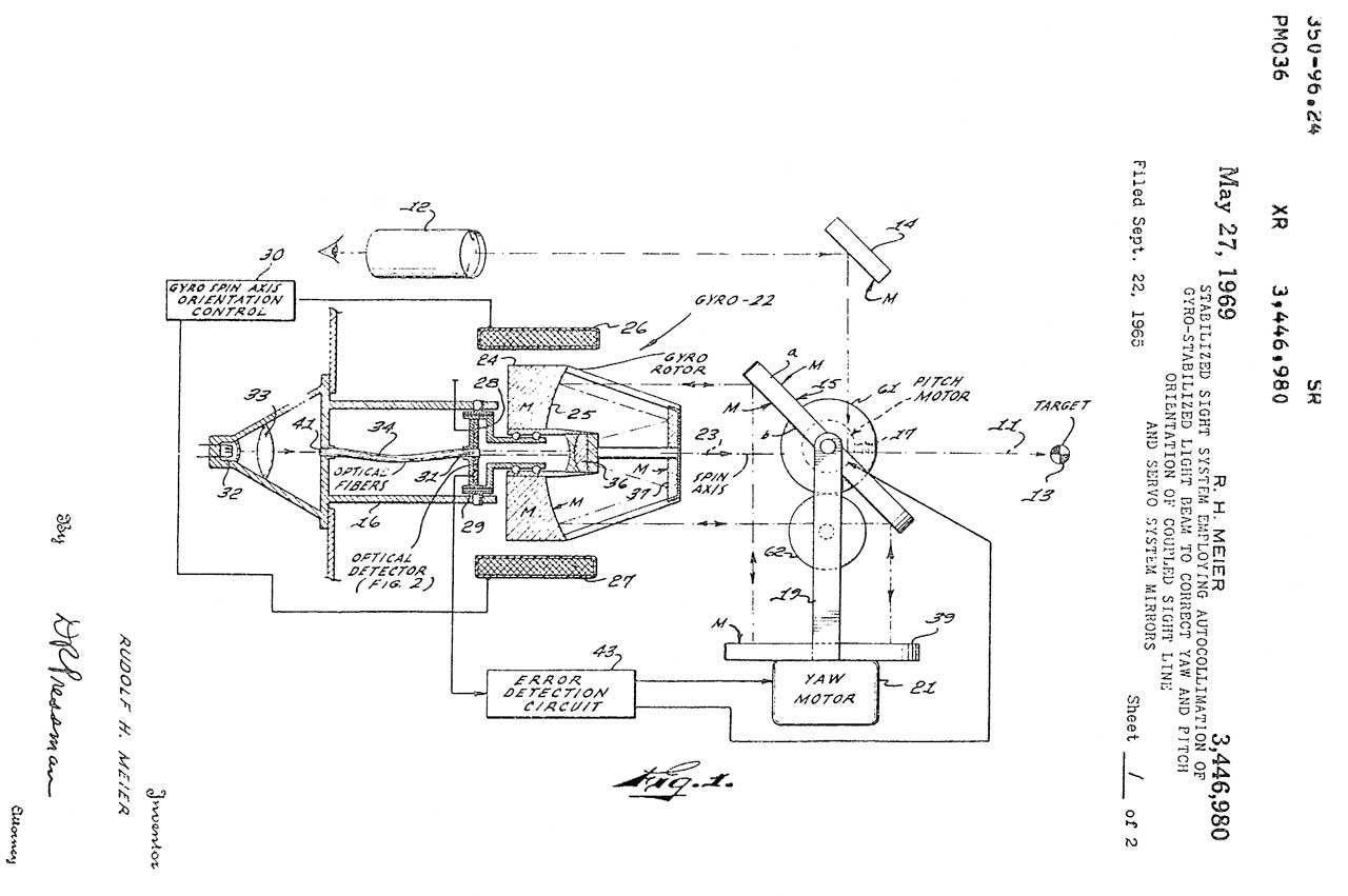
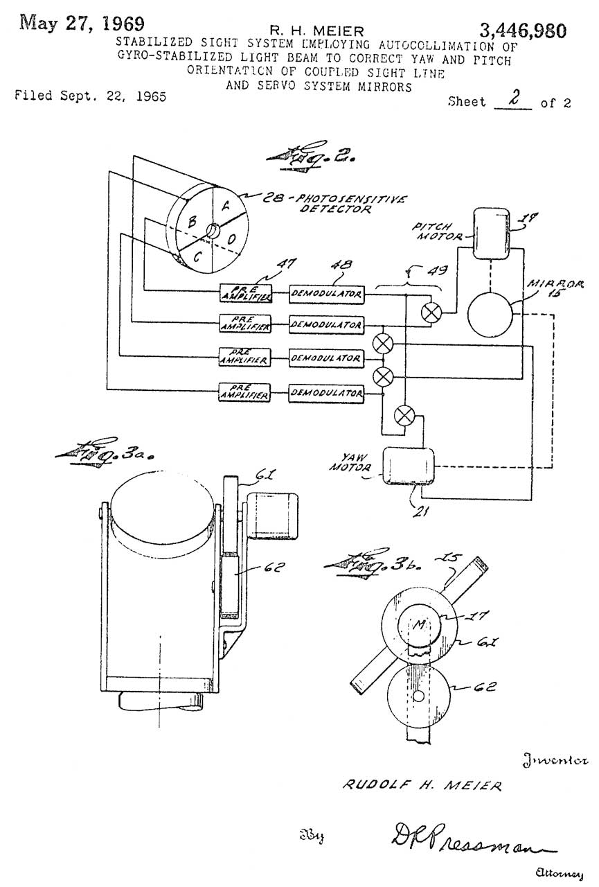
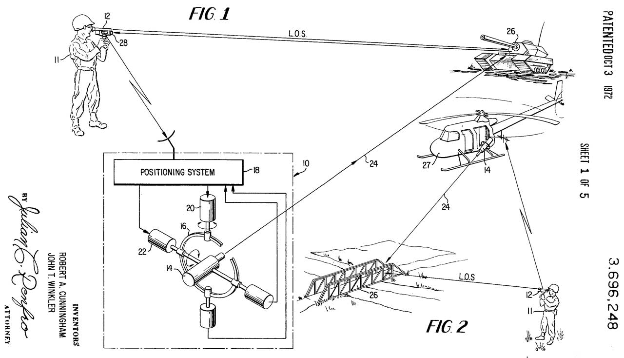
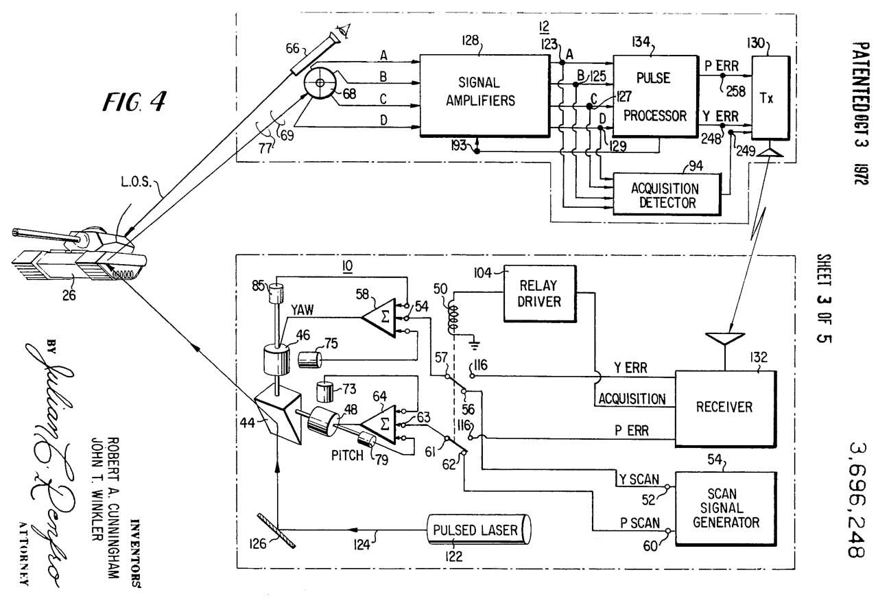

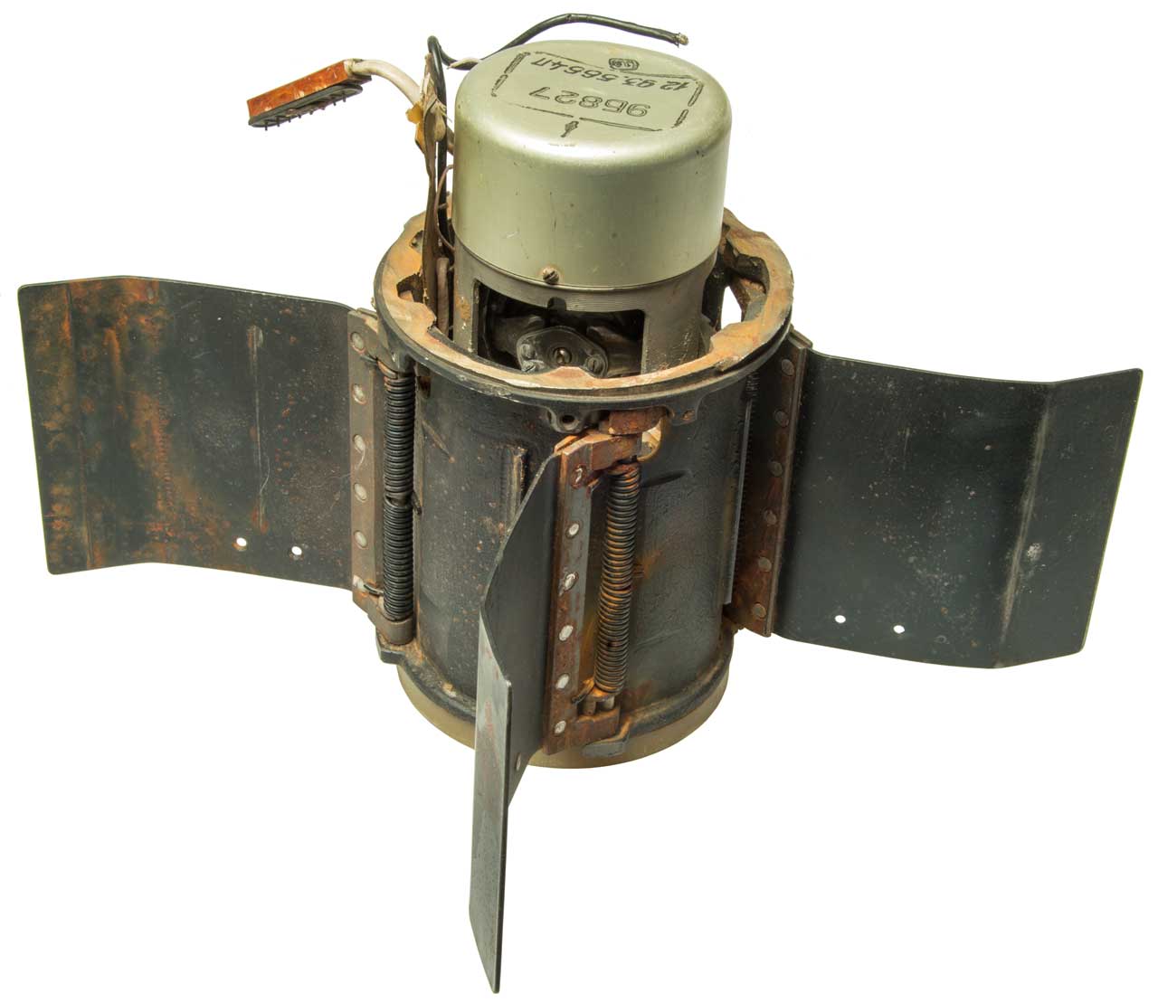


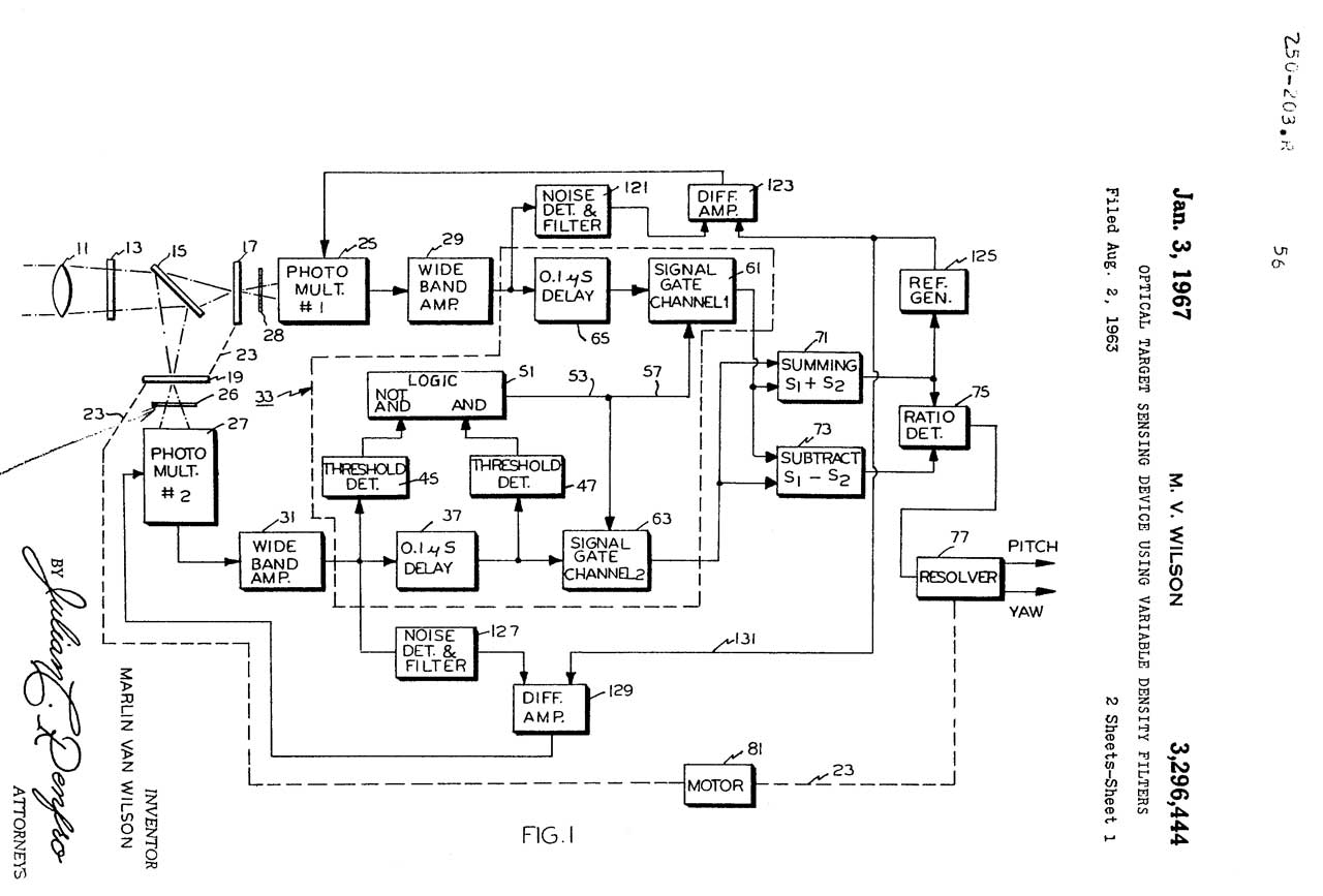
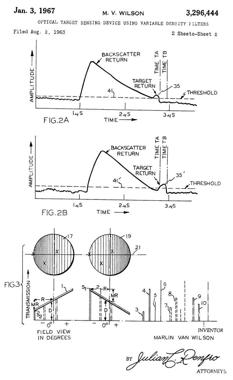
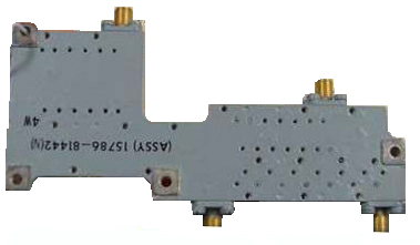