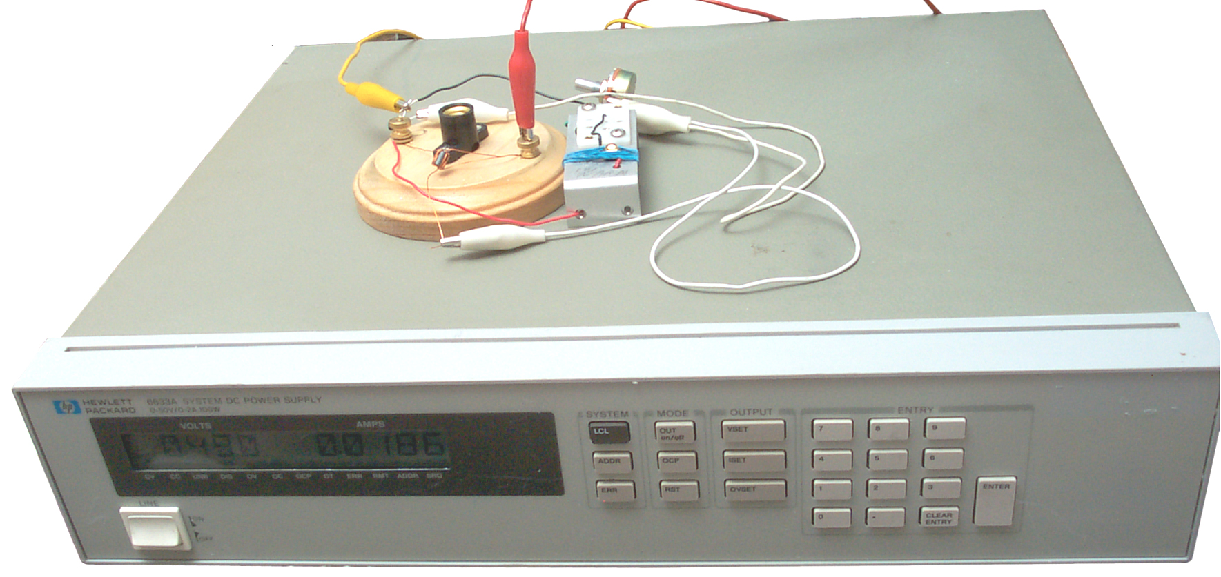
 HP 6633ASystem DC Power Supply
When the manual for a military radio is written the equipment listed for bench test is what was standard issue at the time. To run the same test today you can substitute more modern equipment as long as the newer equipment has equal or better specs.
For serial numbers in the format iijjAnnnn adding 60 to ii is the year made, jj is the week, the letter is the country where made.
for example 1848J02842
- 18 -> Made in 1978
- 48 -> Weeek # of last prodcution change 48
- J -> Made in Japan, or A = America, G = West Germany, U= United Kingdom
- 02842 actual serial number of instrument
The series prefix doesn't represent the date of manufacture. Instead, it represents the date of the last production change that affects form, fit, or function, or for other modifications such as firmware version changes. We use the series prefix to tie production changes (changes in production documentation) to changes in customer documentation.
Because of the FM capture effect the way receiver sensivity is measured must be different for FM and AM radios. AM radios have no capture effect.
SINAD FM receiver sensivity
This is an acronym for "SIgnal Noise And Distortion". It's defined as:
SINAD = 20 * LOG((RMS Value of Signal, Noise and Distortion)/(RMS Value of Noise & Distortion))The inclusion of noise and distortion with the signal is the way a distortion analyzer works, i.e. it measures everything then notches out the test tone. The prior signal to noise ratio was difficult to measure because it required a spectrum analyzer to measure the signal all by itself.
I think the values used for SINAD when the HP 300 series analog distortion meters were popular was 10 dB. But these meters used a average reading AC voltage detection method that was in error about 2 dB for non sine signals. With the introduction of the 8903 and other true RMS reading distortion analyzers the spec was changed to 12 dB to produce about the same sensitivity readings as the prior analog instruments. (The 8903 has an internal jumper option to connect an average reading detector if compatibility with the older 300 series instruments is needed).
The common modern definition of receiver sensitivity is the power level that produces a 12 dB SINAD.
The idea is that there are two factors contributing to the received audio signal to noise ratio in an FM receiver. First as the signal strength increases from the noise level the audio output gets quieter (this is even when there is no modulation on the carrier). Second as the signal strength with modulation increases from the noise a 1 kHz tone will get stronger. The difference between the true RMS audio output with the tone modulation on and the true RMS audio output with the tone modulation off is the SINAD.
Distortion Analyzer
One way to measure this in a single step is to use a SINAD meter or a Total Harmonic Distortion (THD) meter. Both of these methods notch out the 1 kHz tone and can measure both the tone and what's left. The advantage of this method is that you don't need to turn the 1 kHz modulation on and off. This would be very good when testing the SINAD in the field from a transmitter at a remote fixed point.By using a real SINAD meter like the HP 8903B/E Audio Analyzer the transmitter can be sending a constant 1 kHz tone and the meter will notch out the tone and report the SINAD. This would allow drive testing using GPS in the mobile unit or using a time log to allow plotting SINAD vs. position of the mobile unit. Note for receiver testing the "E" version (no audio gen, just the meter) of the 8903 is about 1/2 the price of the "B" version (internal audio gen).
True RMS Voltmeter
Another way to measure SINAD is to just turn on and off the modulation (note the carrier is left on all the time). This has the advantage that you only need a true RMS voltmeter instead of the SINAD meter or a THD meter like the TS-723 (HP 330 series) distortion Analyzer. I am using this method with the HP/Agilent 8648A signal generator and HP/Agilent 34401A Multimeter under computer control so that a plot can be made of both the plain AF noise output, the 1 kHz tone output, and the SINAD. The problem with this is the requirement to turn on and off the modulation. Easy to do on the bench but more difficult when a mobile unit is driving.The Distortion Analyzer, THD and SINAD - college experiment that gives the equations and explanation of SINAD
FM Modulation Tutorial -
Receive Audio Frequency Response
By using a signal generator like the HP/Agilent 8648A with option 1EP and a voltmeter like the HP/Agilent 34401A a plot of the audio frequency response can be made. It's interesting that the PRC-25 has a peaky response centered at 300 Hz but the PRC-126 has a fairly flat response from 100 to about 9,000 Hz. This is probably because the PRC-126 was designed to support voice encryption over an even wider audio bandwidth and the SPKR audio has been low pass filtered to improve the s/n for clear voice.This plot was used in a before and after manner when the PRC-25 was upgraded to the PRC-25B to support multiple channel telephony.
Transmit Output
There are a number of parameters to look at on the transmitted signal:Power
Can be measured with a power meter like the PRM-34 or similar meters.Frequency
Can be measured with a filed test meter like the PRM-34 or a modern spectrum analyzer like the Agilent 4395A. When the transmit output frequency is not known the spectrum analyzer is a great tool to find the frequency.FM Deviation
Can be measured with a deviation meter like the ME-505 or ME-525 but can also be measured directly on the Agilent 4395A or other spectrum analyzer. The HP 8901 Modulation Analyzer is a modern version of the ME-505/525.Harmonic and Spurious outputs
The spectrum analyzer makes this an easy test but it could also be done using a receiver, but finding spurious outputs with a receiver is very tedious unless a computer can do a spectrum sweep.
This paragraph is for equipment that I either have now or have used. Since I do LabVIEW programming, instruments with IEEE-488() and/or RS-232 so that they can be computer controlled are a plus for me. You can get a lot more out of an instrument when a computer is in control vs. manual operation.
Analyzers
DC Power Supplies
| Model |
Watts |
Volts @ Amps |
| 6030A |
1200 |
200 @
17 |
| 6031A |
1064 |
20 @
120 |
| 6032A |
1200 |
60 @ 50 |
| 6033A |
242 |
20 @ 30 |
| 6035A |
1050 |
500 @ 5 |
| 6038A |
240 |
60 @ 10 |
HP 6633ASystem DC Power Supply
| Model |
Out 1 |
Out 2 |
Out 3 |
Out 4 |
| 6621A |
80W LV |
80W LV |
- |
- |
| 6622A |
80W HV |
80W HV |
- |
- |
| 6623A |
40W LV |
80W LV |
40W HV |
- |
| 6624A |
40W LV |
40W LV |
40W HV |
40W HV |
| 6627A |
40W HV |
40W HV |
40W HV |
40W HV |
| Output |
Low Range |
Hi Range |
| 80W LV | 7V @ 10A |
20V @ 4A |
| 80W HV | 20V @ 4A |
50V @ 2A |
| 40W LV | 7V @ 5A |
20V @ 2A |
| 40W HV | 20V @ 2A |
50V @
0.8A |
| Model |
Voltage (V) |
Currernt (A) |
| 6632A |
20 |
+/-5 |
| 6633A |
50 |
+/-2 |
| 6634A |
100 |
+/-1 |
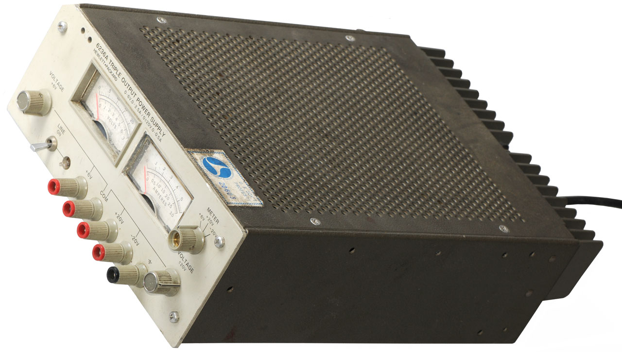 |
This was purchased very
used to replace the HP E3631A Triple Output Digital Power
Supply. The problem with the E3631A is that after a
power failure it defaults to all three outputs at zero
volts. The 6236A uses front panel knobs to set the voltage and so comes up from a power failure at the set voltages (+5, +12 and -12 in this case). Note: There are only two voltage adjust knobs. One for the 0-6 Volt supply and the other controls both polarities of the 0-20 Volt outputs. But there are seperate metering switch positions for each of the three supplies. |
| when connected to the
Thunderbolt GPS receiver, both the +12 and -12 were at zero and the 5V was low. C33 s.b. 490 uF @ 85V tests at 54 Ohms ESR & 0.53 uF so is bad. When removed it tests as an open. It's across the +7.5V rail, maybe why the +5 output has limited range. Since this supply also powers the op amps and reference voltages it may be the only problem. Caps on order 21 Feb 2011. |
HP 6236A C33 Date Code
7626L i.e. it's 35 years old The vent (hole in center on right) is intact, i.e. it has not blown. Test open for DC and capacitance. 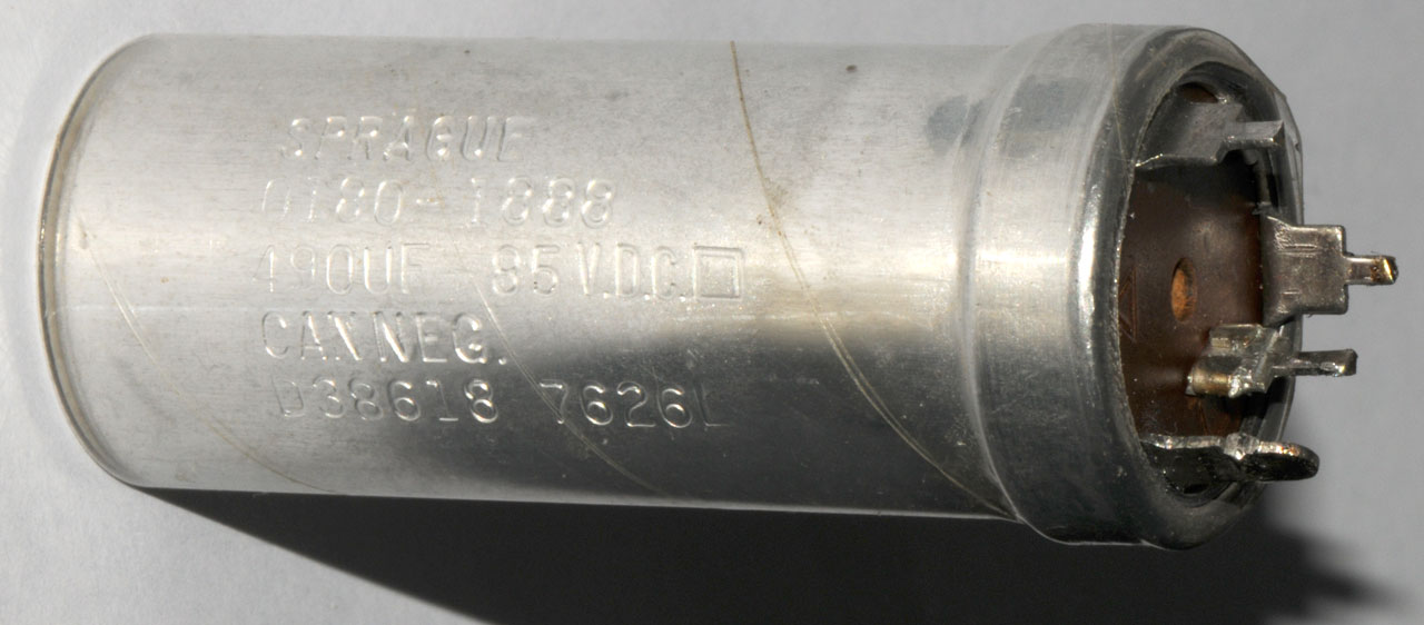 |
| Model |
W |
V @ A |
| E3610A |
30 |
8 @ 3 or 15 @ 2 |
| E3611A |
30 |
20 @ 1.5
or 35 @ 0.85 |
| E3612A | 30 |
60 @ 0.5
or 120 @ 0.25 |
| E3613A | ||
| E3614A | 48 |
8 @ 6 |
| E3615A | 60 |
20 @ 3 |
| E3616A | 60 |
35 @ 1.7 |
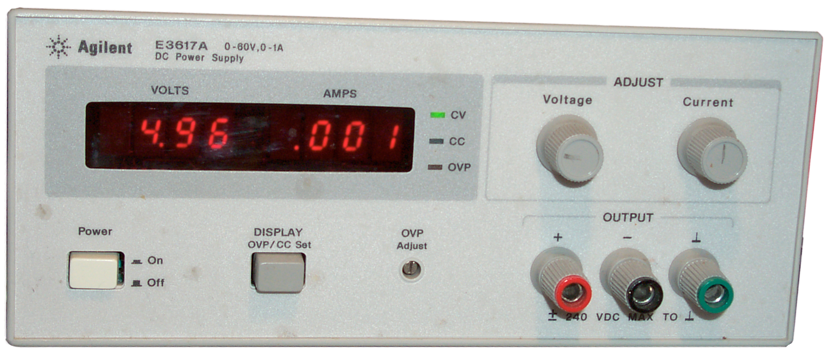
E3617A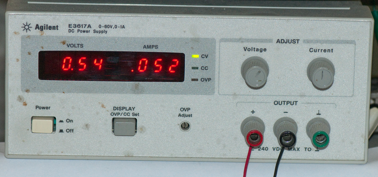 This is my most used power supply. |
60 |
60 @ 1 |
| E3620A | 50 |
25 @ 1
and 25 @ 1 |
| E3630A |
35 |
6 @ 2.5
and +20 @ 0.5 and -20 @ 0.5 |
| E3631A Not suitable for long term use. It resets when the power fails. |
80 |
6 @ 5 and +25 @ 1 and -25 @ 1 |
| E3632A |
120 |
15 @ 7 or 30 @ 4 |
| E3633A |
200 |
8 @ 20 or 20 @ 10 |
| E3634A |
200 |
25 @ 7 or 50 @ 4 |
| E3640A |
30 |
8 @ 3 or 20 @ 1.5 |
| E3641A | 30 |
35 @ 0.8
or 60 @ 0.5 |
| E3642A | 50 |
8 @ 5 or 20 @ 2.5 |
| E3643A | 50 |
35 @ 1.4
or 60 @ 0.8 |
| E3644A | 80 |
8 @ 8 or 20 @ 4 |
| E3645A | 80 |
35 @ 2.2
or 60 @ 1.3 |
| E3646A | 60 |
2X 8 @ 3
or 2X 20 @ 1.5 |
| E3647A | 60 |
2X 35 @
0.8 or 2X 60 @ 0.5 |
| E3649A | 100 |
2X 35 @
1.4 or 60 @ 0.8 |
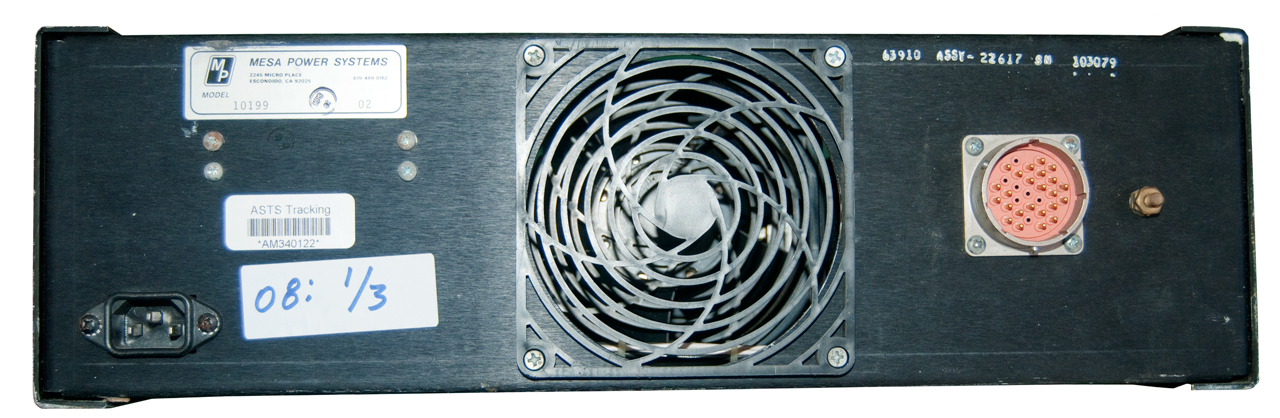
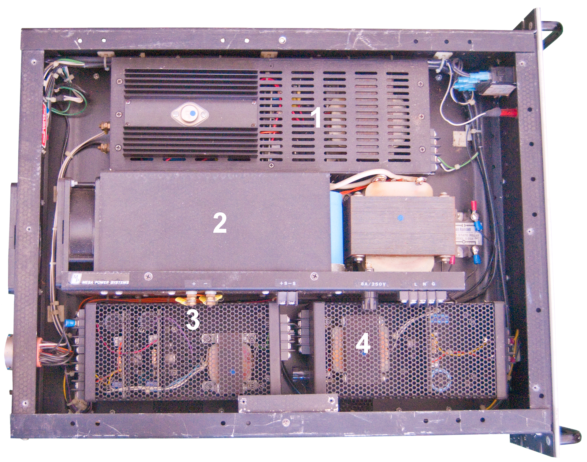
Mesa Power Systems Model 10199 Power Supply Aircraft
My hope was that this would contain a 400 Hz 3-phase supply, but instead it has a number of DC power supplies.
Note aircraft "14 Volts" is exactly the same a ground vehicle "12 Volts" just as aircraft "28 Volts" is the same as ground vehicle "24 Volts".
These power supplies are set for the upper end of the range for each voltage (12V = 10 to 15 and 24V = 20 to 30).
No.
Volts
Max
Amps
Max
Watts
1
28 (30V ?)
5
140
2
15
25
375
3
+5
-5
5
1
25
5
-----
30
4
15
2
30
I'm going to remove each supply and use No. 2 and 4 by connecting "12 Volt" Power pole connectors. Note "12 Volts" means 10 to 15 Volts so these are perfect.
No. 1 will have a "24 Volt" power pole connector added. No. 3 will go on the shelf.
Front panel only has circuit breaker and pilot lamp
Top View with numbers for each power supply
Topward 33010D 0-30V, 0-10A.
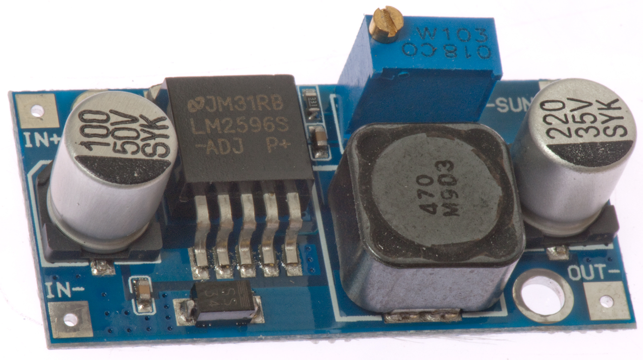
Switching Mode Power Supply Modules
On eBay you can buy ready made printed circuit boards with a SMPS circuit.
Note: a SMPS can be thought of as a transformer for DC.
If you look at the voltage x current at the input it's about the same as a voltage x current at the output.
While in operation the output power as a fraction of the input power (efficiency) is typically in the mid 90% range.
DSN2596 based on LM2596
40/4 VDC input, 35/1.3 VDC adjustable output step down only.
 Calibrated
using an HP 34401. Very low cost ($27.50).
Calibrated
using an HP 34401. Very low cost ($27.50). This 4000 count
meter has the ability to work for DC amps which is the key thing I
got it for. The lowest DC Amp range is 4.000 A full
scale. To use the range after powr on and waiting a little
for the meter to stablize press the ZERO button. Then
connect to the wire carrying the current.
This 4000 count
meter has the ability to work for DC amps which is the key thing I
got it for. The lowest DC Amp range is 4.000 A full
scale. To use the range after powr on and waiting a little
for the meter to stablize press the ZERO button. Then
connect to the wire carrying the current.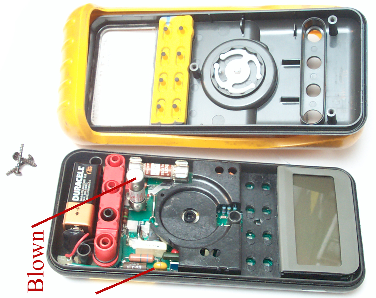 |
When trying to test a Weston 594 Photonic
cell no current could be measured, but it did have
voltage output. Also voltage across a shunt 100
ohm resistor. A fuse was blown when trying to test
Flash Amps
on a Leclanché
Battery. The self test on the Fluke 87 is to probe in Ohms mode between V-Ohm-diode connector and the mAuA connector where you should see 1 k Ohm. The test Failed. Also the fuse check is to remove test leads, select V= or V~ plug a test lead into uAmA - meter should click if fuse is good. Failed Plug test lead into A - meter clicks if fuse is good. Passed The yellow component is NOT blown, it's a spark gap. F2 is the 11 Amp fuse and the one I remember as blown. So not sure which one blew. I suspect it was the 11 Amp fuse because the expected Flash value was on the order of 10 Amps. |
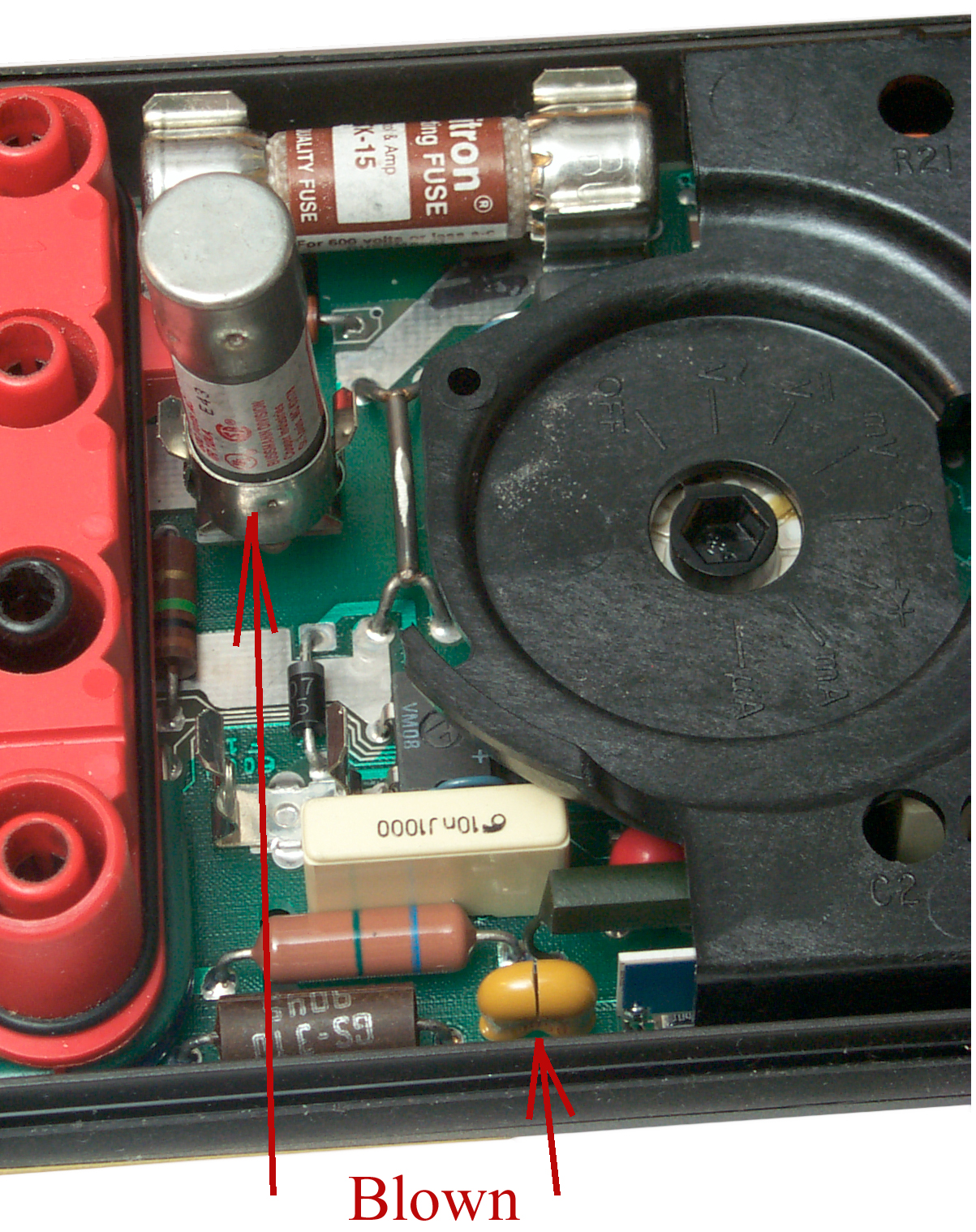 |
The fuse that's standing
up (F1 0.44 A) is open Also the yellow part OK. |
| It
turns
out the 1k resistor from the bottom of the mA/uA jack
that gets shorted by the range switch when in the mA
range is not part of the analog circuitry but rather
part of the digital monitoring of where the test leads
are plugged in. So it was reinstalled along with
the adjacent four pin DIP bridge diode and a wire
soldered across the blown fuse terminals. After
reassembly not only are the mA and uA ranges working but
also the back light now works. There must have
been a bad connection (see What
Goes Wrong) between some of the parts that's
now good. |
|

| Heathkit IT-10 Transistor-Diode Tester -
simple way to ID diode and transistor polarity and get a
rough idea of beta. The IT-27 may be the same tester
with different color paint. This tester is very simple and seems to be very reliable. You get some idea of relative beta. |
 |
||
| Heathkit IT-121
Transistor & FET Tester Uses a couple of "D" batteries and a 100 uA meter movement to test Beta, gm, and a number of leakage currents. Needed some contact cleaner in the switches and pots (was used by a heavy smoker). The 166 Ohm cal resistor is supposed to be taped to the inside of the front panel (it's used for setting the pot on the PCB, but if not you can make one by connecting two 100 ohm resistors in series then connecting that 200 ohm resistor in parallel with a 1000 ohm resistor. |
|||
Front Panel |
Back Instructions |
Inside |
|
| GE
Transistor Manual "Safe
and Simple Transistor Tester'. Made this
for work when we were buying Ge microwave transistors
and characterizing them ourselves rather than pay TI a
lot extra to sort them. The 150 Ohm cal resistor
is built in on S4 so to do the full scale cal just press
BATT TEST and S3. You can get numbers for beta, and a number of leakage currents. |
 |
||
|
TS-1836C/U
- Military in and out of circuit tester also tests FETs
and diodes. Uses self rectification of square wave
input to generate a DC output when xixtor is in a common
base configuration. So far not very useful. . . . does not work, why? |
 |
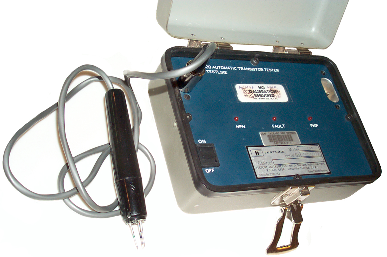
||
| TL-120 - rechargeable
battery powered tester, automatic detection of NPN or PNP,
no settings or meters, just LEDs for PNP, NPN & Fail
LEDs. NSN 6625-00-367-9323 patent 3870953 In-Circuit Electronic Component Tester 324/72.5; 324/537 made by Testline. Uses a single probe that has three plunger type pointed tips so you can contact all three transistor PCB pads with one hand. Handy probe and quick check. |
 |
||
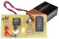
| This
Electronic Goldmine
tester uses a 555 oscillator driving a Flip Flop
to act as a DPDT switch reversing the polarity to a common
emitter configuration. By noting which of two LEDs
turns on you can tell the polarity of a transistor.
But you need to which terminals are the Emitter, Base and
Collector. Not too useful. The schematic diagram for this kit should win an award for the most convoluted, upside down and twisted schematic possible for such a simple circuit. |
 |
||
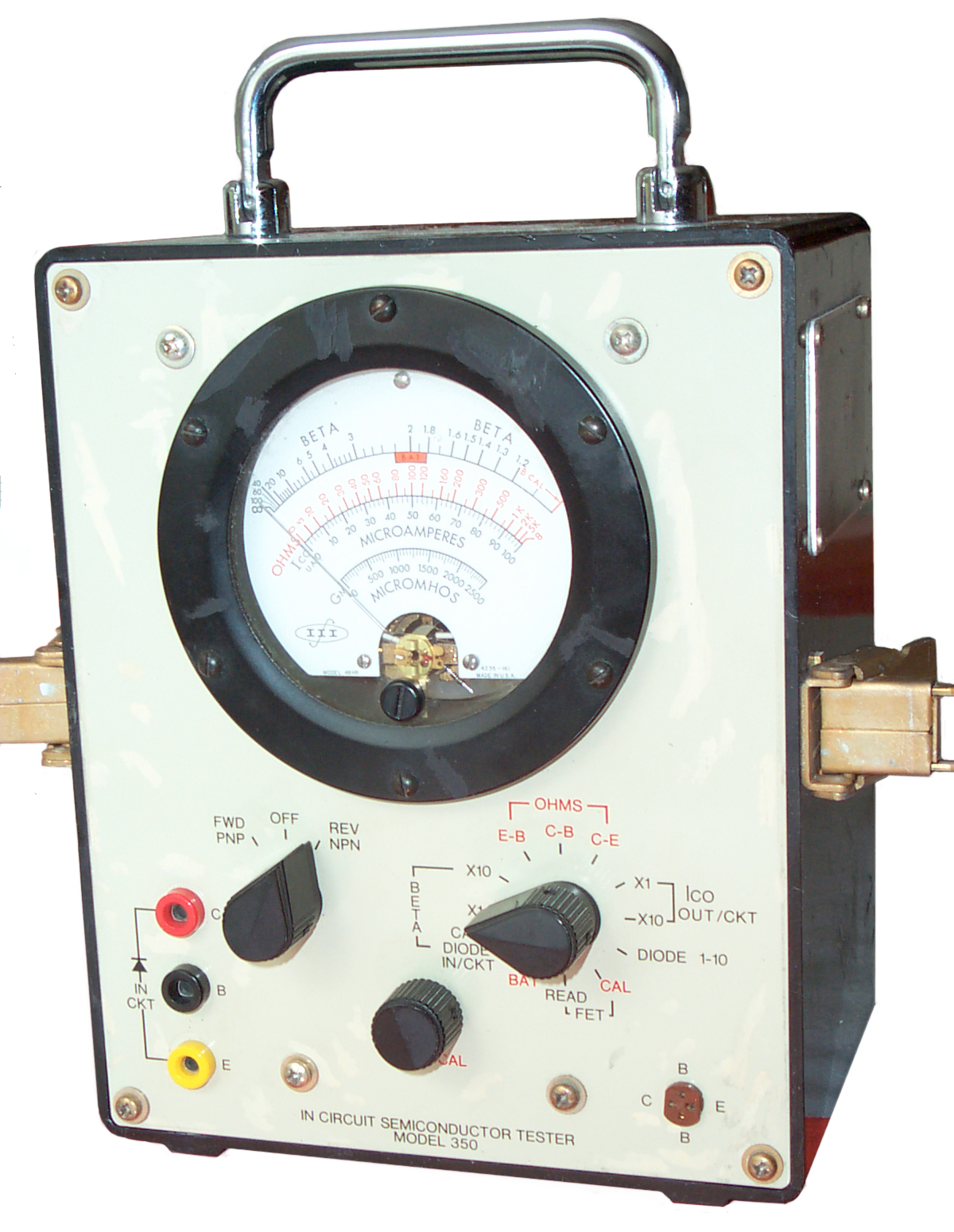
| M3
Semiconductor Analyzer - 2004? - my Ver 3 kit was
built in 2007 This is the most advanced unit for the price. Although there are a number of things I'd do to improve it. There are three test leads, each of which is fed using a series resistor that's selectable (100k, 10k, 1k or 100 Ohms) and that resistor can be connected to either +5 or ground. There's a DC voltmeter on each lead. So by driving the leads two at a time and subtracting voltages you can find the voltage across the DUT. Also since the voltmeters are after the series resistors you can also find the current at each lead. I'm having a problem with calibration. It may be that I've just got some high resistance mux chips (M3 is sending 3 more chips at no charge, good support by Mike). It turns out that if there's solder flux left on the board it can allow leakage to the high impedance voltmeter inputs. Radio Shack no longer carries flux cleaner, so it's not available in my small town. Isopopropal alcohol did not work. But acetone did work.
It's great for sorting out grab bags of 3 leaded devices. I'm planning on adding a machined pin IC socket cut down to 3 terminals in addition to some nice E-Z-Hook grabbers to replace the cheezy ones that come with the kit. Based on the PIC 16F876 uC and using three each 74HC4052 Dual 4-Channel Mux controlling resistors of 100k, 10k, 1k or 100 Ohms on each of the three test pins. The MAX4618 has much lower On resistance and has the same pin out. M3 Semi Anal Ver 3 (M3SA_Manual.pdf) Kripton2035: Semiconductor Tester Repository - |
 |
||
| Peak
|
|||
Shenzhen DY294 Digital Transistor DC Parameter TesterThis unit runs from 6 VDC, either 4 internal AA cells (although the battery compartment can hold 6 cells, but two positions have no electrical contacts) or using a female plug wall wart.It can test transistors for: VBR, VCEsat, hFE, Iceo. 3-terminal voltage regulators with 27 Volts input. Withstanding voltage on electrolytic caps up to 1000+ VDC. This tester has a current limited high voltage supply that is activated when the TEST button is pressed (the red LED warning lights when high voltage is present). When measuring the forward voltage drop on a semiconductor at 800 mA or 2 A the external 6 V @ >=2A power supply should be used. |
 |
||
| YouTube: Teardown
and Review of the VC60B+ Insulation Tester/Megohmmeter,
18:42 - |
|||
Professional Type Semiconductor AnalyzersI wrote many HP Basic programs to drive the HP semiconductor analyzer boxes like the 4142 & 4145 DC box and the related LCR meters. |
|||
Transistor - L/C ESR TesterShown measuring a 470 uF 10 V cap as 482.6 uF &
ESR=.01 Also has provision for SMT parts. If the SMT LED
was removed it might also be used to test LEDs? The Markus
Frejek tester based on the AVR uC dates to 2009. ArduTester - Arduino & prototype board. - same as the multi-tester with the rotary encoder.
|
 |
||
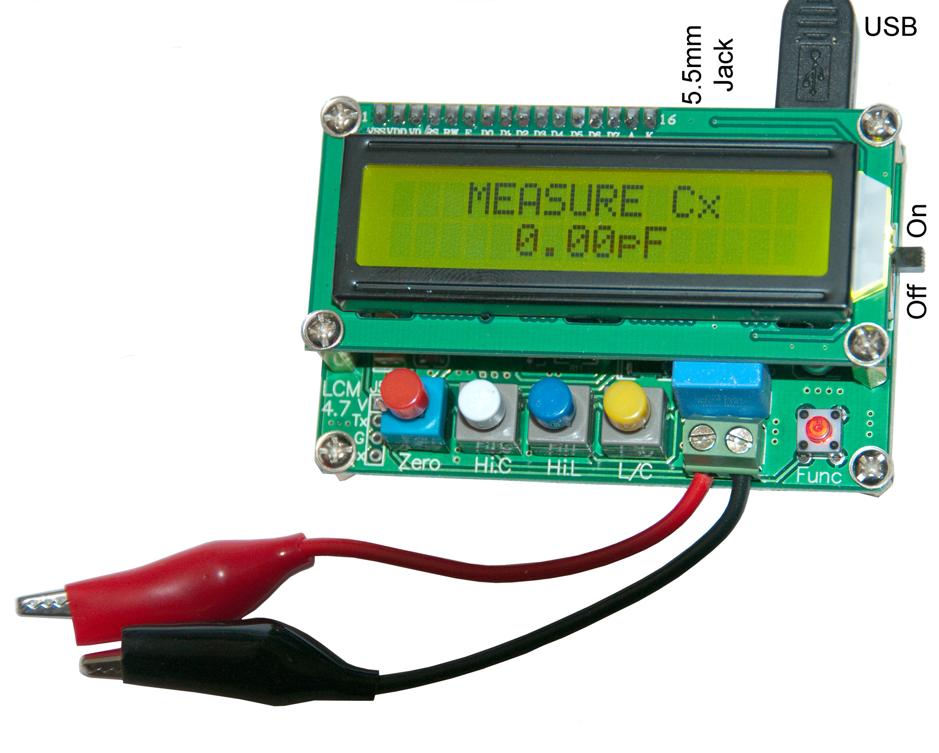
LC100-A L/C TesterThis tester is limited to testing inductors or
capacitors, but it does that better than the more
general purpose testers. Comes with short test leads that are connected to screw
terminals. Pushing the red button at the lower right displays the
test frequency (which changes with component value
because this tester works be resonating the DUT with a
component that's part of the tester. May be a knockoff of the AADE L/C Meter. Note (Up/Down) the White (/HiC), Blue (/HiL) and yellow
(C/L) buttons are latching. |
 |
||
| Fluke 87 (or any DMM with a diode test) can be used
to check for the Base-Emitter and Base-Collector junctions
of a transistor. This is a very powerful method
that's also simple. But it's more time consuming
than more advanced test methods. In diode test mode the
red lead is positive and the test current is 1 ma (this is
a very good way to do this since the Vf of most diodes is
specified at 1 ma). If a transistor tests as two
forward diodes with the red lead common then the
transistor is an NPN but of the black lead is common then
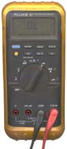
it's a PNP. Most silicon PN junctions have a Vf of about 0.6 volts. Silicon Schottky junctions range over 0.28 to 0.35 depending on the barrier metal. Germanium is more like 0.4 volts. The 87 is the first piece of test equipment that I use. If you're going to only have one test instrument this is it. The only time it failed me was when checking a lawn sprinkler system and the 87 showed voltage at the valve but the valve was not activating. The Fluke 12 showed no voltage in the "V-check" where the input impedance is 1 k ohm. |
 |
||
| 2024 May 15 TC1
Multi-Function Component Tester These have been on the market for maybe a half dozen years and are an iteration of the M3. Claimed Specifications: Built-in rechargeable Li battery (battery voltage show on most screens). 3.5 x 3cm TFT color screen (with graphic device symbols) Diodes with Vf up to 4.5 V Zener diodes up to 30V (when correctly inserted into KAA sockets) Transistor dect 0.01 - 4.5V Triac Range: Igt < 6mA Capacitance: 25pF - 100mF Resistance: 0.01 Ohm - 50 MOhm Inductance: 0.01 mH - 20H Battery Voltage Test 0.1 - 4.5V (DO NOT EXCEED 4.5 V) Reads some IR remote codes. YouTube 433 How Transistor Testers Work and How to Use them?, 21:29 - overview of how they work |
|||
TC2 Multi-Function Component TesterThis version has many more IR remote protocols, and
maybe other differences. TC-T7-H Full-Color Multi-Function TesterIt's not clear what the differences are between the
TC1, TC2 and T7-H. |
|||
Transistor Test Set Related PatentsClass 324/768 Electricity Measuring & Testing/ (537) Of individual circuit component or element Bipolar transistor(768)Moved to the TS-1836 Patents |
|||
These are instruments that show up in the military radio manuals but that I don't have. Just for info.
Mil Nomenclature Description Commercial Nomenclature Power Const Key Spec(s) AN/USM-37
SWR Test Set
HP 415 + Slotted lines
115/230
Tube
1 kHz narrow band amp.
AN/USM-281C Oscilloscope Tek 7603N11S
TM 11-6625-1703-24P120/220 OS-246A/USM-281D Oscilloscope Dumont 115/230 OS-189/USM-281A Oscilloscope HP 180+
PL-1186A PL1187AUSM-425 Oscilloscope Tek 465M 115/230 or
24 VDC BattOS-8 Oscilloscope TM 11-1214
TM 11-6625-252-20115 OS-106/USM-117 Oscilloscope TM 11-6625-640-24P
TB 9-6625-342-35Transistor USM-338 Oscilloscope solid state USM-140B Oscilloscope Tek 531? SG1174/U Sig Gen AUL 6201B
TM 11-6625-2952-24Ptube 3.8 - 7.6 GHz SG-297/URM-103 Sig Gen TB 11-6625-586-12/1 tube 18 - 80 MHz FM SG-376 2 tone IF Sig Gen Transistor 497.5, 498.5, 501.5, or 502.5 KHz SG-823 2 tone Ref Sig Gen 2, 3.6, 4, 14.4, 16, 28.8 MHz /URM-25 Sig Gen TM 11-5551B
TM 11-6625-278-20P
TM 11-6625-603-40P10 KHz to 50 MHz AM SG-117/URM-26B Sig Gen 115 4 to 405 MHz AM-CW-Pulse SG-1170/1171 Sig Gen Wavetek 3001
TM 11-6625-2952-24P
TM 11-6625-3029-14,-24P
TM 11-6625-3051-12, -24P, -40
TB 9-6625-2094-35
SG-1144 Sig Gen P TM 11-6625-2954-14&
TM 11-6625-2954-24P50 kHz - 80 MHz URM-103 Sig Gen TM 11-6625-586-12,
-12/1, -24P, -458350B
Sweep
Gen
HP 8350B
TB 9-6625-2124-35
USM-207 Digital Counter
TM 11-6625-700-10
-14-1, -25, -24P
CP-772A/U
HP 5245L
TM 11-6625-1682-24P
USM-459 Digital Counter HP 5328
TM 11-6625-2941-14&P
TM 11-6625-2701-35
TB 9-9925-2334-35
AN/USM-323 Sig Gen HP 8640B-323 500 KHz to 512 MHz AM-FM-Pulse TS-403 Sig Gen TM 11-5091
HP 616B1.8 - 4.2 GHz SG-557/TS-621 Sig Gen 3.8-7.5 GHz USM-441 Time Mark Gen Ballantine 6130A 120 TS-1010/UPM-84 Spectrum Analyzer 115 tube 10 MHz to 44.88 GHz ME-180/USM-116 AC-DC Voltmeter 115 tube 20 Hz to 100 MHz
1 to 300 V fsME-440/USM-381
to 15 kVDiff DV VM Fluke 896A
1 kV0-10-100-1000 VDC ME-297/USM-223 Multi Meter 6-PXB1 1.3 V
1-"C"
conved
2 AA + 1 CFET 2.5 V - 5 KV
0.25 - 10 A DC
1K - 10 M Ohm
HP 3478
TM 11-6625-3071-14
ME-77/URM-105C Volt - Ohm TM 11-6625-203-12,
-24P, -352 ea. AA
22.5 V?1 - 1000 V AC/DC
2k - 20 M Ohm
30 Hz-10KHzURM-127(A) Audio Osc TM 11-6625-683-14, -24P
TB 9-6625-1998-35115 solid state 20 Hz to 200 KHz
Audio Osc
HP 202C
TM 11-6625-589-15
DA-43/U Dmy Ld &
Watt Mtr28VDC 0.2 to 20 MHz
2 to 100 WTS-3329/U HP 236A
TM 11-6625-2903-14&PDPM-3 Power Meter 30 to 600 MHz
50 and 150 W rangesME-165/G SWR Meter TM 11-6625-333-15, -24P
TM 11-809-20, -35up to 30 MHz
600 WURM-120A Watt Meter 2 to 1000 MHz
10 to 1000 WDA-75/U/URM-120 Dmy Ld TM 11-6625-446-15 2 to 1000 MHz
10 to 1000 WME-82 Watt Meter M 11-6625-595-34 50-600 MHz
120 WDA-189/GRC Dummy Load 600 to 1850 MHz
40 WDA-727 Dummy Load 30 MHz
800 WZM-4 DC Bridge TM 11-2019
TM 11-6625-249-12P, -34P
TB 9-6625-388-353 each D no active devices
1 ohm to 1,011 M Ohm ZM-11 AC Bridge Navships 91704A 115 tube TS-505 VTVM TM 11-5511
TM 11-6625-239-12, -34Pbatt tube URM-145 Voltmeter TM 11-6625-524-14 ME-26B/U Multimeter HP 410
TM 11-6625-200-12,
-15, -24P, -35TS-352/U Multimeter TM 11-6625-366-10,
-15, -24PTS-723/A/B/C/D Spectrum Analyzer TM 11-6625-255-14,
-24P, -34P
HP 330x Distortion AnaME-505 Modulation Meter TM 11-6625-3017-14
TF 2300A
ME-525 Modulation Meter TM 11-6625-3059-10
82AD
ME-57 Modulation Meter TM 11-6625-400-20P, -35, -40
TM 11-6625-2629-14&P, -24P
TB 9-6625-2004-35
tube type
USM-44 Sig Gen HP 608 URM-18 Distortion Analyzer HP 333A
TS-4084/G Distortion Analyzer Tek DA 4084 ?
NSN 6625-01-217-0054
TM 11-6625-3152-14
Tek 1502
TDR
TM 9-4935-601-14-3&P 115AC/230AC/12DC
1 to 2,000 feet of line
HP 530x Counter
TB 9-6625-2215-35
LA-387A
HP 5233L Counter
TM 11-6760-242-24P
5001A Stanford Telecom 5001A Navstar Test Transmitter - made to test their GPS receiver ICs
AMREL EL-1132 Electronic Load
BatTst Battery Testers
Beltone 12D Audiometer - hearing test - audio
Capacitors table with ESR and Cap measurements for different types - table of test data
CEI CEI Tempest test Receiving System & TEMPEST related
CI (Crystal Impedance) Meters
Crystal Activity Meter
DC Gaussmeter Model 1
AMY6 Magnetic Polarity Tester
GE Gauss Meter & Reference Magnet
DDD Digitech Digital Data Signal Generator System
Dig2150A Digitech Serial Data Generator model 2150A
DMM Digital Multimeters
Eppley Standard Cells & Pyranometers
ESR-micro - ESR Tester & Coil ring tester
Exotech 100BX Radiometer - optical spectrum test
F600 Frederick Electronics 600A BER Tester
F91120 F91120 Field Radio BER Test Set
FCP Frequency Counter Patents
Frequency Standard, Audio (Anti Reverse Engineering design)
F.W. Bell 640 Incremental Gaussmeter -
GDO Millen 90651 Grid Dip Meter
GMQ-33 Cloud Height Set
GPend Onset G-Pendant, 3-axis accelerometer data logger. also see the Hobo 4 external channel - data logging
GravityMeters Gravity Meters
GR 358 Wavemeter
GR650A General Radio GR 650-A & GR 1650B Impedance Bridges
GRsound General Radio Sound Measurement Instruments
GRM55 TS-1755A/GRM-55A for the PRC-25
Harris TS1000 ADSL Test Set
Harris TSP-21 Telephone Test Set Plus (like but set, but belt-clip & operators headset)
Helmholtz Coil
Sensitive Research Instrument Co. Fluxmeter
Annis M25 Pocket Magnetometer
Cenco Scientific 79860 Dynamo Analysis Apparatus - works with Fluxmeter
Hilger & Watts Spectrometer D 168.3/290 - optical spectrum
Home Built Magnetometers
Honda Optimate 3+ Desulfating Battery Charger, Maintainer, Tester
HP 117A HP 117 WWBV time standard receiver
HP 204B Audio Oscillator from HP 3350 Carrier Test Set (AN/USM-181 Telephone Test Set
HP 241A Audio Oscillator w/Radio Buttons
HP 2748B High Speed Rack Mount Paper Tape Reader
HP33120 HP 33120 Function Generator
HP 3437A System Voltmeter
HP 3458A DVM (very accurate if it can be fixed)
HP 415E SWR Meter
HP 4260A Universal Bridge
HP 4261A LCR Meter
HP 427A Voltmeter AC & DC Volts & Ohms
HP 4274A & HP 4275A LCR Meters
HP 4328A Milliohmmeter
HP 4332 LCR Meter
HP 4395A Combination Network, Spectrum, Impedance Analyzer
HP 5004 Signature Analyzer
HP5060A HP 5060A Cesium Beam Frequency Standard
HP5100 5110A Synthesizer Driver & 5100A Frequency Synthesizer
HP 5110A Synthesizer Driver & 5100A Frequency Synthesizer
HP 5216 HP 5216A 12.5 MHz Nixie Tube Electronic Counter
HP 5342A Microwave Frequency Counter
HP 5345 Counter
HP 54501a HP 54501A Digital 100 MHz Oscilloscope
HP 59000 Family HP-IB Accessory Modules
HP 6038A Power Supply
HP 6200 Scanner Problem (was WIN98 Problem)
HP 66311A Mobil Communications DC Source
HP 71100C 2.9 GHz Spectrum Analyzer
HP721A HP721A Power Supply
HP8406 HP 8406A Frequency Comb Generator
HP 8648A 100 kHz to 1 Ghz Signal Generator w/ pager option
HP 8702B Lightwave Component Analyzer - Electro Optical Network Analyzer - 8753A Network Analyzer
HP AC-4A Decade Counter module (4 tubes + Neon bulbs)
HP-IB Controllers
HP E1938 Ovenized Crystal Oscillator
HP E6450B GPS Drive Test Receiver
HP K79 Custom In House Diode Test Set K79 0981C
HP Z3805A Time & Frequency GPS Receiver
HT20 2000 mT Magnetic Flux Meter
Huntron Tracker In Circuit Component Tester
Inductors Inductors
James V-Meter V-Meter Mk I -measure concrete properties
Kelvin Connection Measurements
KGS Electronics SPC-6-1000-3PH 50/60Hz to 400Hz 3-Phase Frequency Changer - AC source
KS8455 KS8455L2 Line Loop Tester Telephone Installers & Repairman's Meter
KS-24361 (Lucent ) HP/Symmetricom Z3809A, Z3810A, Z3811A, Z3812A GPSDO System
Length & Weight Measurements - tools
LM631A Amprobe (Meterman) LM631A Digital Light Meter
Marconi TF-2700 Universal Bridge
MC1 MC-1 Magnetic Compass Calibration Set similar to AN/ASM-344
ME-165/G Standing Wave Ratio - Power Meter
ME61 ME-61/GRC Meter, Field Strength, H.F.
Megger - Holtzer-Cabot Meg Ohmmeter ZM-14A/PSM-2
MHC777P2 Maha C777 Plus II Battery Charger, Analyzer, Cycler
MHC9000 Maha MH-C9000 AA/AAA Charger, Analyzer, Discharger, Break-in, Cycler
Microwave Test Equipment - Network (Vector & Scalar), Power
Millen 90651 Grid Dip Oscillator (Meter)
MK2137 MK-2137/PRC-68 Maintenance Kit
ML-OSA Monolight Optical Spectrum Analyzer
& Beseler PM1 Darkroom Color Analyzer
& Wollensak L3524D Direct Vision Spectroscope
& Ocean Optics HR2000 Spectrometer
Model NS-LB White Noise Generator
Noisecom 7110-FAC Programmable Noise Generator
NTgpsSTR2760 Northern Telecon GPS Satellite Sumulator STR2760
NSLB Model NS-LB Noise Generator
office_equip Instruments in my Office when I did this web page
PC based Oscilloscopes - Went with the Rigol box scope
PP2953 see PP-6224 Line Powered 24 Volt power supply
PP6224PwrSup PP-6224 24V Power Supply & Harris RF-5051-PS001
PP7286 PP-7286/U Battery Charger Time & Current
PP7601 PP-7601 6 Station Battery Charger Navy/Marine charger for PRC-68 family batteries
PP8249 PP-8249 SINCGARS Battery Charger, mainly for tanks, but I don't think it was ever used?
PP8444 PP-8444A/U Universal Portable Charger (UPC) small suitcase charger for BB-xx90
PP8496 PP-8496/U Self Discharge Device w/Capacity Meter
PP8498 PP-8498/U Soldier Portable Charger (SPC) Multi-Port Universal Battery Charger AC or DC input
PRC2577TstAdp PRC-25 & PRC-77 Test Adapter for POWER connector
PRM32 PRM-32 (TS-20) Test Set, Survival Radio
PRM34 TS-3951/PRM-34 VHF Low Band "God Box"
Probeye Hughes Probeye Infraed Thermal Viewer
PSA-45D Avcom PSA-45D Portable TVRO Spectrum Analyzer - looking at signals coming from the LNB
PSM13 PSM-13 Battery Test Set
PSPatent RF & Microwave Power Sensor Patents
PTR Phase Tracking Receivers
PTS 160 Frequency Synthesizer
Q Meters
RF204 Detector RFI, RF-204 (not really bug detector, though might work)
Rigol DS1052E Oscilloscope
Seismometer - Seismometer & Geophone
SG-1144/U Signal Generator 50 kHz to 80 MHz
SG-886A/UR Interference (Noise & Tone) Generator
Shielding Integrity Monitoring System II RP98G & RP98D for screen-SKIFF rooms
SidekickTandN Tempo Sidekick T&N Telephone Line Tester
SOC Chemtronics LS 91 & LS 94 TS-4403/U & TS-4403A/U Battery State of Charge Meter LiSO2 7 to 9 AH
SR715 LCR Meter
Standard Electric Time Co. S-1-24 Timer (Stop Clock)
Subscriber Loop Analyzers
TandFTE Time & Frequency Test Equp:
Gibbs Crystal Oscillator
Stanford Research SC10 Crystal Oscillator
Stanford Research PRS10 Disiplined Rubudium Oscillator
HP 53132A Counter
Frequency Standard
Stanford Research SR620 Counter
HP 33120A Function ARB Generator
HP 8648A Signal Generator
Stanford Research DG535
HP 54501 Scope
Tektronix 1502 Metallic Time Domain Reflectometer
Teledyne Avionics TA-3D Acoustic Impedance Meter
TelephoneToolKit Telephone Tool Kit
Telephone Tone and Probe
Testing Small DC PM Motors, DC PM Motors, Flywheel
TF2700 Marconi TF-2700 Universal Bridge
TF_rack Time & Frequency Rack anotated photo
TMQ34 TMQ-34 Meteorological Measuring Set
Triton2 Charger Discharger Cycler
TS183 TS-183B/U Battery Tester & Large Table of Military Batteries
TS1775 TS-1775 Relay Test Set
TS1836 TS-1836 Transistor Test Set
TS23 TS-23 Light Output & Battery Tester for SDU-5/E Strobe Light
TS24B TS-24B survival Ratio Test Set
TS-2839/GY German Audio Test Set - H-3 & related audio connectors
TS3354 Squad Radio Test Set TS-3354
TS-3647/G, Control Orderwire Unit (COU), Telephone Test Set
TS4082PTPT100 TS-4082/URC PTPT-100 Test Set for the PT-25A, PT-25E, URC-100, URC-101, URC-104, URC-110, URC-111
TS585 TS-585 Audio Level Meter
TS799 TS-799/UGM-1 TTY Test Set (Pattern Generator)
URM106 Stoddart URM-6 Set, URM-106 Field Strength Meter 14 to 250 Kc
URM182A URM-182A TS-3754/U VHF Low Band Power Meter
USM-159A Hetrodyne Frequency Meter - transistorized version of the BC-221 (SCR-211) and LM series
USM481 USM-481 Test Set VINSON Interconnecting Boxs & Cables
Victor VC2000 Crystal & Frequency Meter
Walker Scientific MG-3D Gaussmeter
Wavemeter GR 358 Kit
Weston594Photronic Weston Model 594 Photronic Cell light sensor, & Weston 614 & Weston 615 Foot Candle Meters
Xam Crystal Activity Meter
Xec Crystal Unit Equivalent Circuit
Xtal Electronic Crystals
Xtal Impedance (CI) meters
Z Impedance Measurements
ZM-11/U Capactance-Inductance-Resistance Bridge, line powered
ZM-4 Bridge battery powered
Ref 1. How To Test 208 Billion Transistors, 29:13 -
3039604 Centralized automatic tester for semiconductor units, Richard L Bickel, Wendell C Brooke, Winthrop J Day, Jr Earl D Mcdonald, Edwin G Millis (Transistor Museum), James L Nygaard, Texas Instruments, 1962-06-19, - CAT (Centralized Auto Tester) - used to select a pair of 2N185 Germanium transistors for the Regency TR-1 Transistor Radio.
3084326 Means for measuring and testing components, Walter B Mitchell, Transitron Electronic Corp, 1963-04-02, -
4092589 High-speed Testing Circuit, Yuk Bun Chau, George Niu, Rudolph Staffelbach, Fairchild, 1978-05-30, - up to 30 MHz input test signal; cited by 57 patents
4523312 IC tester, Kunio Takeuchi, Advantest Corp, 1985-06-11, -
[an error occurred while processing this directive] page created 11 Nov. 2001.