Inductors
© Brooke Clarke 2011 - 2025History
Cores
Theory
High Q
Tesla
Properties
Testing
Toroids
Saturation
Energy Storage
88 mH Telephohne Loading Coil
Telephone Induction Coil
Table
Electromagnets
Miscellaneous Patents
Related
Links
Background
History
It's very difficult to include an inductor in a semiconductor type integrated circuit (IC). Prior to ICs to make a low pass filter you would use series inductors and shunt capacitors, but now it can be done with an op amp and just resistors and capacitors. (see the GR active filter patent that's a key part of the HP 200A audio oscillator) In fact all the common filter types can be realized without using any inductors. With the advent of Switching Mode Power Supplies (SMPS) inductors are much more popular. These require the ability to handle the currents involved in a specific design and be small and low cost. The efficiency of the SMPS depends in a large measure on how low a resistance the inductor exhibits and in fact the specifications for the IC depend on the quality of the inductor used. so it's common that the evaluation boards for a SMPS will use an exotic inductor.
Joseph Henry (Wiki) was the first person to make a close wound electromagnet. He used "Bell Wire" which was uninsulated wire that was used to mechanically ring bells, like to call a servant. He used his wife's spinning wheel to wrap silk around the wire to form insulation (if you have details on how this was done, contact me). Prior to this all the work done with electromagnetism was done with bare wire wound with a large air gap between turns, or a single turn. Insulated wire led to the Telegraph and Stock Tickers which in turn led to Teletype machines that use a binary code for the characters. My first computer used a Teletype model 33 Automatic Send Receive (ASR) for keyboard input, printing, paper tape punching and paper tape input.
Cores (Wiki)
By adding an insulation that was very thin Henry was able to close wind his wire on a soft iron "U" core to make a lifting magnet that could hold many hundred pounds. All the prior experiments with electromagnetism were done with bare wire and so Henry was the first to demonstrate this effect.
"Soft Iron" (Wiki) was the first core material. The soft has two meanings. First, like bailing wire (Wiki) and floral design wire it is easy to bend and shape. Second it does not get magnetized so when the electric current is turned off the electromagnet has almost no magnetic effect. Soft iron can support over a 2 Tesla field without saturating and so is commonly used for electromagnet pole pieces.
In the early days soft iron cores were used in relays (Wiki) and solenoids (Wiki).
Ignition Coils (Wiki), Faradic (quack medical) devices,Violet Ray (quack medical devices), early telephone induction coils used in phones all used a core made up of a bundle of fine soft iron wires.
Later, in some applications, Electrical Steel (Wiki) replaced soft iron for applications where energy efficiency mattered. For example in self winding (Western Union) clocks the clocks made in the late 1800s used solid soft iron cores, but the later clocks used laminated Electrical Steel for the synchronizing solenoid.
Electrical Steel laminations are used as the core of AC transformers and motors. Not only does it improve the efficiency it also allows a construction method where the laminations are built up in overlapping layers.
Ferrite (Wiki) and Powered Iron (Wiki) cores are used to make inductors. These may be in the form of a toroid (Wiki) where there's a closed magnetic path and so very low magnetic leakage or susceptibility. These cores are also available with an air gap to prevent saturation where the application needs that.
When the first turn is would on a core the filling factor comes very close to being 1 (it's a little less because the wire insulation and maybe there's paint on the core). But when a second winding is added on top of the first winding the copper wire of the first winding takes up some of the area under the second winding reducing its fill factor. As more and more layers are added they have less and less inductance per turn.
Theory
Ampère's circuital law (Wiki) - relates the integrated magnetic field around a closed loop to the electric current passing through the loop.
Lenz's Law (Wiki) - An induced current is always in such a direction as to oppose the motion or change causing it
High Q
To get a high Q in operation the load capacitance needs to be much higher than the self capacitance of the coil. That's so say the coil needs to be operated at a frequency that's much lower than it's self resonate frequency. To lower the self capacity of a coil you need to pay attention to both the turn to turn capacitance AND to the voltage between those turns. For example:
1. In a single layer cylindrical coil with a lead at each end and it's tight would you can approximate the capacitance between each turn by assuming the turns are insulated rings. BUT, you also need to look at the voltage between the turns. In this case the voltage between adjacent turns is Vtotal/N where N is the number of turns.
2. In a double layer tight wound coil where the input and output wires are adjacent to each other you can use the same ring approximation for the capacitance between adjacent turns. But now there's a huge problem because of the voltage between turn 1 and turn N. Between these two turns the voltage is Vtotal. That's N times higher than in the case above. This is why using bank winding (see the Loop antenna page) is used as well as breaking the coil into sections is used to minimize the voltage between turns.
See my Q Meters web page for more.
From eBay seller mkmak222_Litz Wire here is a recommendation of Litz wire application:
Note the eBay ads say these are Type 2, the designation, like 660/46 is for a Type 1. Have question to seller to clarify the Type.
Answer: 3/26/46 (78 strands) and 2/27/46 (54 strands) = 132 strands. Then 5 of those bundles are combined: 5 * 132 = 660 total strands.
Strand AWG
Freq kHz
No. of Strands
Bundle AWG:
36
34
32
30
28
26
24
22
20
18
16
14
12
10
8
6
48
1400 - 2800
180
300
420
675
1100
1725
46
850 - 1400
10
20
30
40
60
66
100
175 250
270
330
420
660
924
1162
44
350 - 850
10
20
30
40
60
100
125
160
255
405
550
650
850?
42
200 - 350
16
26
40
66
105
165
270
420
660
1050
40
100 - 200
17
27
42
66
105
108
170
270
435
700
1100
38
50 - 100
16
25
40
66
100
162
200
280
420
660
1050
1650
36
20 - 50
16
27
41
65
105
165
265
35
20 - 50
100
33
10 - 20
13
21
32
53
82
100
150
329?
32
10 - 20
50?
30
1 - 10
7
11
17
26
42
65
28
0.6 - 1
5
7
10
18
27
42
Here is the Cooner Wire web page for Litz wire showing the various types.
For Type 2 (No. of groups)/(No. of strands in a group)/AWG
They claim that putting too many strands in a single bundle (Type 1) does not work as well as Type 2.
Tesla
The best reference book is Tesla's The Colorado Springs Notebook (ISBN-13: 978-9562914628). In the early part he did not have high Q operation and showed photos of each complete setup. Later, after adding a metal pipe vertical antenna with capacitive top loading so that the secondary coil was operating with a load capacitance much higher than it's self capacitance, he only photographed parts of the setup to keep some secrets. He mistakenly thought he had power multiplication, rather than just the voltage multiplication that comes with high Q operation.
Note: the demonstration "Tesla Coils" that are sold for school demonstrations are not really high Q coils but rather are just RF transformers. Their output voltage is just the input voltage stepped up by N^2. In a true Tesla coil there would be a capacitor in parallel with the secondary and the output voltage would be Q * N^2. Note it takes measuring the spark length between a couple of large metal spheres or a high voltage probe (these are over $1,500 used on eBay) to measure the voltage, not the gap between points.
The units used for wavelength, Inductance and Capacitance were all meters.
Properties
Any coil of wire will have some resistance and an ideal inductor would have zero resistance. There are a number of sources of resistance and the show up as different slopes is a plot of coil Q vs. frequency. The DC resistance does not change with frequency. The resistance because of skin effect (Wiki) and proximity effect (Wiki) can be mitigated by using Litzendraht wire (Wiki). The dielectric loss (Wiki) in the wire insulation is also a factor. For example some insulation materials are lossy at RF frequencies as some coil coatings may be.
There is also capacitance between the turns of an inductor and as the frequency is swept the impedance (Wiki, my Impedance page) of the inductor goes through at least one resonance. At a fixed frequency the ratio of the inductive reactance (Wiki) to the resistance is called the Quality or Q (Wiki) of the inductor. When used to form a resonant circuit with an external capacitor the Q of the circuit is inversely proportional to the bandwidth of the circuit. Varnishing or coating a coil to hold the turns in place or moisture proof the coil also adds capacitance.
Testing
There are a number of ways of measuring inductance. One way of characterizing the different methods is to look at the measurement error as a function of frequency. This is covered in The Impedance Measurement Handbook by Agilent. The most accurate method makes use of the 4-terminal pair connection method as used by such instruments as the HP 4274 and HP 4275 LCR Meters.
For measuring the Q specialized equipment is more accurate than using general purpose equipment. The Boonton 160 Q meter was an early instrument that uses a 4-pin vacuum tube. There was a motorized accessory for the HP 4285A that allowed it to measure Q.
2137787 Method and Apparatus for Electrical Measurements, H.A. Snow (Boonton Radio Corp), Nov 22, 1938, 324/654; 324/653; 338/61 - 160 Q-Meter
Class Numbers:
324 Electricity: Measuring and Testing
653 Impedance, Admittance or other Quantities Representative of Electrical Stimulus/Response Relationship
Lumped type parameters
For figure of merit or Q value
654 Impedance, Admittance or other Quantities Representative of Electrical Stimulus/Response Relationship
Lumped type parameters
Using inductive type measurement
338 Electrical Resistors
61 with Inductance-Reducing
The HP 4395A can measure the impedance of a series connected component over the frequency range of 10 Hz to 500 MHz with a Resolution Band Width (RBW) as narrow as 1 Hz.
Rather than looking at the inductance and resistance at a single frequency a better method is to make a swept measurement and fit a model to the data. This way you capture not just a 2-element model, but a more complex model. This is the professional way to measure crystals.
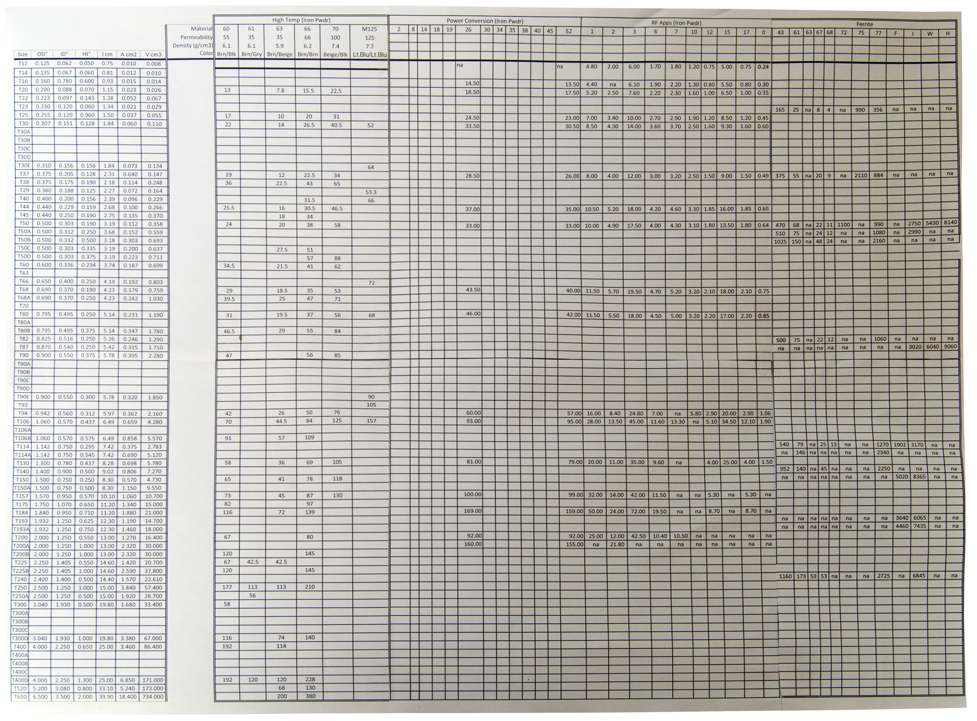
Toroids
Note the Tnn size designation is based on the OD in inches.
A T100 core would have an OD of approximately 1 inch, a T 50, half inch, etc.
The first step was to make a spreadsheet listing the sizes down the left side and the materials along to top with AL values in the main body.
Note ferrite toroids are commonly named FTnn, but I've dropped the F and list them with all the other toroids.
A blank cell or "na" in a cell means no part with that material and size was found on the first try.
There were a number of sizes where there was a suffix letter like T50, T50A, T50B, T50C & T50D.
If a high letter suffix was found but no lower letters they were listed anyway.
In the case of T200A and T200B they seem to be the same?
It takes 6 letter size pages to print, so here's a photo of the AL chart.
It seems that the first step in figuring out what material you have is to measure the physical OD, ID and Height of the core.
This will eliminate the vast majority of the possible cores.
Now measuring the AL value should narrow down the possible cores.
Example No. 1:
Marking: 8620 55305-A2
Color: Gray
OD: 0.909
ID: 0.5395
Ht: 0.304
The T90 is: OD 0.900, ID: 0.55, Ht: 0.3 and the T90E is OD: 0.90, ID: 0.55, Ht: 0.3
Don't have dimensions for the T90A, T90B, T90C or T90D so not sure what size this is.
Example No. 2:
Color: body: light green, one face: Blue
OD: 1.306
ID: 0.632
Ht: 0.451
The ID is slightly smaller than the T130 listed & the Ht is a little bigger.
Example No. 3
Marking: 482S 77934-A7
Color: shiny black
OD: 1.066
ID: 0.573
Ht: 0.456
This is very close to the T106 and so might be material: 60, 63, 66, 70, M125, 26, 52, 1, 2, 3, 6, 7, 12, 15, 17, 0
An AL measurement would narrow that down. It's also not a ferrite, but rather powdered iron.
Example No. 4
Color: light green body, one face blue (same as Ex No. 2 above)
OD: 2.012
ID: 1.24
Ht: 1.008
This is a T200A (same as T200B) so the material might be: 26, 52, 2, 60, 66 all powdered iron
Example No. 5
Color: light green/blue one face yellow
OD: 3.047
ID: 1.925
Ht: 1.005
This is a T300D and the material might be: 60, 63, 66 oin powdered iron
Example No. 6
Marking: -MB4- 55321-04
Color: light brown
OD:
1.424
ID: 0.869
Ht: 0.415
Example No. 7
Marking: 563S 77548-A7
Color: shiny black
OD: 1.3" (broken so a guess)
ID: 0.82 (broken so a guess)
Ht: 0.427
By comparing this one with Ex. No. 3 the marking might be decoded?
A toroid is shaped like a doughnut. Since it has a closed magnetic path there is little magnetic leakage if the turns are a single layer wound close to the core.
Different materials behave differently with frequency and power.
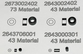
These toroids were ordered for experimenting with the Joule Thief LED circuit. These are Fair-Rite RFI suppression cores.
Distributors that carry toroids: Amidon and Mouser also see my Disty web page.
|
 |
Toroid Equations
There are different ways a toroid can be wound.
One way it to get as many turns as possible. For these
applications the "Fill Factor" becomes important.
What you're looking at is how many square mills of wire area
can you fit into the hole area. If the wire diameter
was very small the fill factor will be near maximum but as
the wire size increases the fill factor gets smaller because
of the air gaps were there are no turns.
Another way is to wind a single layer coil. Again
smaller wire sizes allows more turns than larger wire sizes,
but smaller wires have more loss. This may be the most
effective way since each turn has the most core
material. If more than one layer is would then the top
coils have some core and some copper filling their ID.
Length of a Turn
For a single turn of a single layer wound toroid:Lturn = 2*(OD-ID) + 2*Len
Example for the first two rows of the table above, Lturn = (0.38 - 0.197) + 2 * 0.19 = 0.563
Then 10 turns would take 5.63" of wire plus a couple of 4" leads is about 10" of wire.
AL
Each toroid has an AL value that allows the number of turns needed for a given inductance to be estimated.N = SQRT(L/AL)
AL = L / (N*N)
Examples with 10 turns, AL = L(10 turns) / 100
First row AL = 50uH /100 = 0.5 uH
Second row AL = 170uH / 100 = 1.7 uH
Saturation
In a magnetometer (Flux Gate Patents) when the core is saturated there's no change in the Earth's magnetic files, but when it's not saturated the Earth's filed is concentrated. The difference between these causes an AC output proportional to the field strength (especially at the second harmonic of the drive frequency).
The core memory (Wiki) used in early computers requires that the core remains saturated in one of two directions. The X and Y drive wires carry just over half of the needed amp turns to flip the core magnetization so only the core that has both X and Y driven will be flipped (if it was magnetized in the opposite direction).
Energy Storage
But the current (I) is limited by saturation of the core material. A way around that limitation is to insert a narrow air gap into the core. When measuring the core current in the Joule Thief another core that was the same as the working core was used as the current transformer and the drive current was limited by the source impedance of the HP 33120 Function Generator. A more flexible method would be to use a FET and bench power supply so that the source resistance would be near zero and the voltage could be higher allowing for higher currents.
The energy is stored in the non magnetic parts of the core structure, either in an air gap or in the non magnetic binder that holds the material together.
For a transformer where you want low core losses it's good to have a lot of magnetic material and not much air. Electrical steel (Wiki) is used in thin sheets to minimize Eddy current (Wiki) losses. This was a big improvement from solid iron bar cores. The use of a bundle of soft iron wires in the core of induction coils (Faradic machines, quack UV light machines, telephone induction coils) was an improvement on the solid iron rod cores of the first generation coils.
88 mH Telephone Loading Coil (Wiki)
Mihajlo Pupin (Wiki) patented Pupin Coils in 1899.
Trivia: It's not unknown for the inventor to not understand how his device really works. An example is the Griffin Grinding Mill (see my Gyroscope web page.)
Loading coils come in two different colored wires (red and green). A single winding has a DC resistance of 4 Ohms.
In the telephone application these were used to "load the line". There are two key ideas: 1) If the signal could be transformed to a higher impedance the line resistance would cause lower loss. This is the method used to deliver AC mains power by means of transformers. Transformers are not a viable option in telephone circuits because they do not pass the DC signaling, but the line impedance can be raised using series inductors. There is a decrease in line loss of about 1.4 dB per mile (1.6 dB/mi to 0.2 dB/mi. It's best if a 500 or 2500 telephone is used that compensates for the distance between the phone and the central office. Older phones will not work as well. 2) A low pass filter can be formed where the inductance is that of the line plus the added loading inductor and the capacitance is that of the line. For 88 mH coils the typical distance between coils is 6,000 feet. At the start and end of the line the distance is 3000 feet. Testing should be done within that range and is typically done at 1 kHz for audio signals.
Also see my web page on line impedance when operating below the critical frequency. Details on the use of loading coils can be found in BC Burden's 1948 Handbook for Telephone Managers and Engineers.
Note: Loading should only be done between the central office and a single phone. If a party line phone is connected somewhere in the middle of the line the loading will not work properly and the loss may (probably will) increase. A party line could be implemented by having home run circuits from the CO to each subscriber and bridging them in the CO using bridge lifters (Saturateable inductors that present a high impedance at voice frequencies to the line(s) that are not in use to prevent them from imposing a shunt capacitance across the line circuit, which would degrade transmission on the pair that is in use. The DC current through the inductor connected into the active line saturates it, causing its impedance to drop to a negligible value.)
Wiki: Primary line constants: Loaded Line
Some vacuum tube power supplies included a "swinging choke" whose inductance changed with the current flowing, i.e. very similar to the telephone saturable inductor.
| As received the same
color coils were connected together by adhesive
tape. Some care was used when separating each
coil |
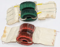 |
| There are four leads
since this is a dual coil, or transformer. Just as the
schematic symbol has one of the wires for each winding
marked with a dot this has one wire marked with yellow
sleeving. When testing a winding (one yellow & one non yellow found by experiment) it measures about 22 mH and a Q of about 150 But when connected as shown (in series) the inductance is 87 mH with a Q of about 200. Note doubling the number of turns should multiply the inductance by 4 since inductance in proportional to (# turns)^2. |
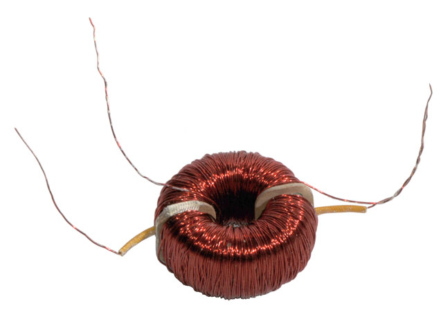 |
It's my understanding that when used in phone service the individual coils would be connected in series with the tip and ring wire pair. Some type of test would need to be done (you can tell from the mechanical layout of the coil) to be sure tip went to tip, i.e. that the wires were not reversed. They are connected so the yellow sleeve points the same way for the DC current, i.e. one pointing to the CO and one pointing to the subscriber.
519346 Apparatus for Telegraphic or Telephonic Transmission, M.I. Pupin, May 8 1894, 381/98; 307/102; 379/41 -
652231 Art of Reducing Attenuation of Electrical Waves, M.I. Pupin, June 19 1900, 178/45 -
705935 Magnetic core for inductance-coils, John C Lee, Edwin H Colpitts (Wiki), AT&T, App: 1901-11-30, 178/46; 148/277; 336/210; 336/213; 29/607; 252/62.55; 336/234; 29/605 -Ferrite core
705936 Loaded electric circuit, John C Lee, Edwin H Colpitts, AT&T, App: 1901-11-30, 178/45; 336/213; 336/234; 178/46; 336/229 - improvement over solid iron or laminated iron cores.
980921 Loaded phantom-circuit, George A Campbell, Thomas Shaw, AT&T, 1911-01-10, 370/200; 178/45; 178/46 -
1174187 Loading-coil, Thomas Shaw, AT&T, 1916-03-07, 178/46; 370/200; 370/201 - duplex phantom loading coils
1853548 Coil, William L Casper, Western Electric Co, 1932-04-12, 336/234; 148/310; 148/311; 148/312; 420/459; 420/581 - "repeating coil with primary and secondary, the core of the coil consisting of alternate layers or laminations of silicon steel and high permeability nickel-iron alloy commonly known as permalloy,...". works over a wider range of line voltages than prior coils.
http://www.ptsupply.com/pdf/CharlesLoadCoils.pdf - has info on various model numbers and sizes.
Also see my Telephone Poles & telephone patents web pages.
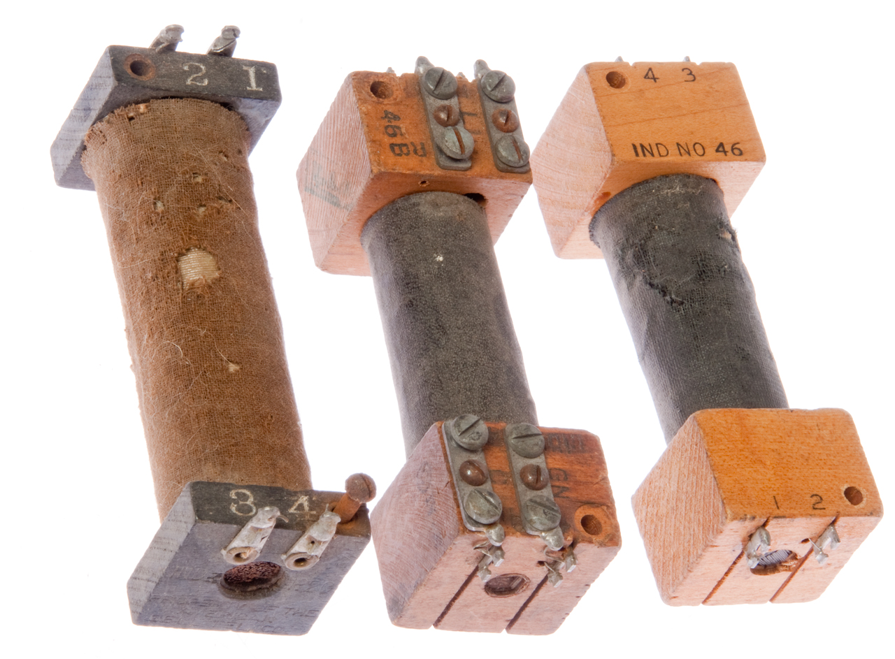
Telephone Induction Coil
These are used as part of a telephone set either as a transformer or as an inductor.
The construction is similar to the violet ray quack medical device and I suspect other "induction" coils in that their magnetic cores are made up of many individual wires or in the case of two of these No. 46 induction coils thin iron plates. Using laminations is another way to make more efficient magnetic paths, but things like "E" and "I" or "L" and "I" shaped laminations are not appropriate for this application (these have a part of the path in air so they will not saturate). This is an improvement on the solid iron cores used in early telegraph equipment.
Resistance: 1-2: 16.48 Ohms, 3-4: 26.78 Ohms.
Note coil acts as an electromagnet since the core is not closed. The core is made up of straight soft iron and works at least through 3 kHz voice frequency.
With a DC Gaussmeter touching the end of the core the magnetic field in Gauss is about the same as the current through the 1-2 coil in mA.
158787 Improvement in telegraph apparatus, T.A. Edison, 1875-01-19, 178/62; 178/118; 200/19.01 - "electric motograph" ?
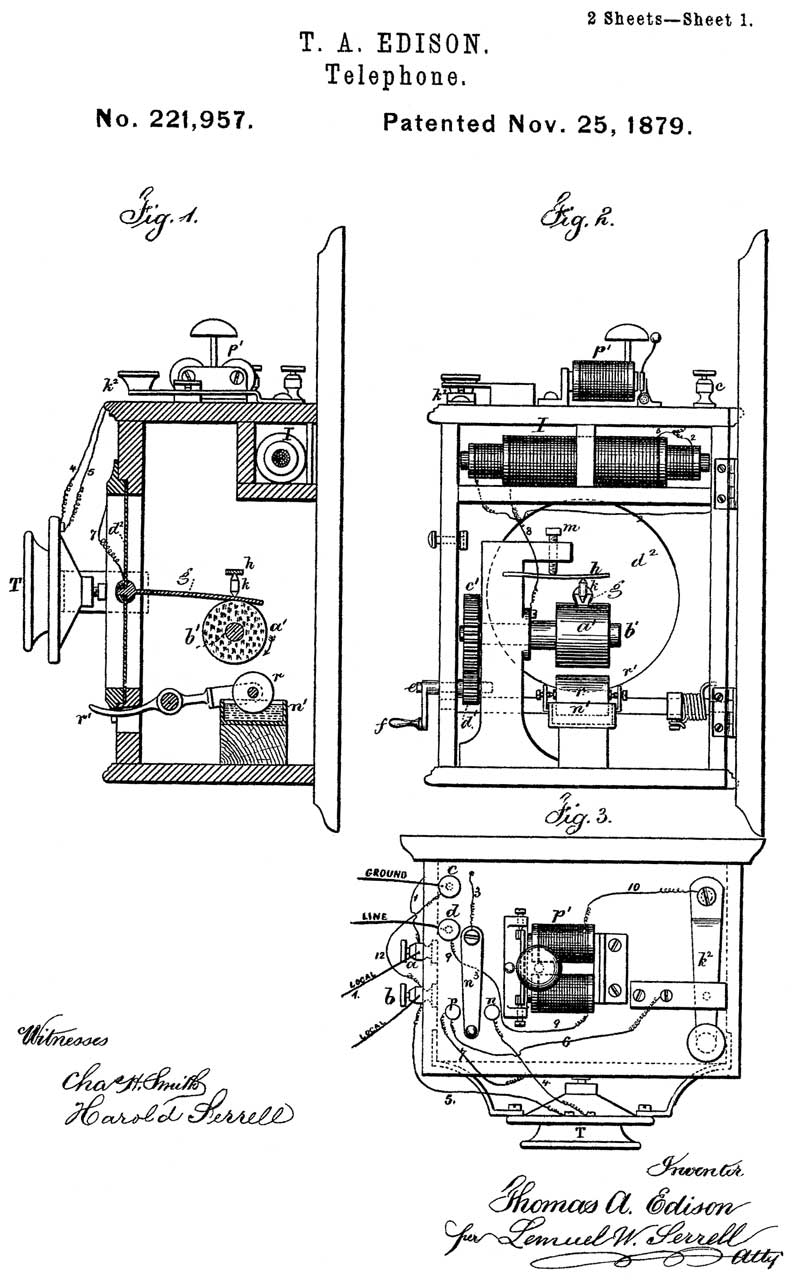
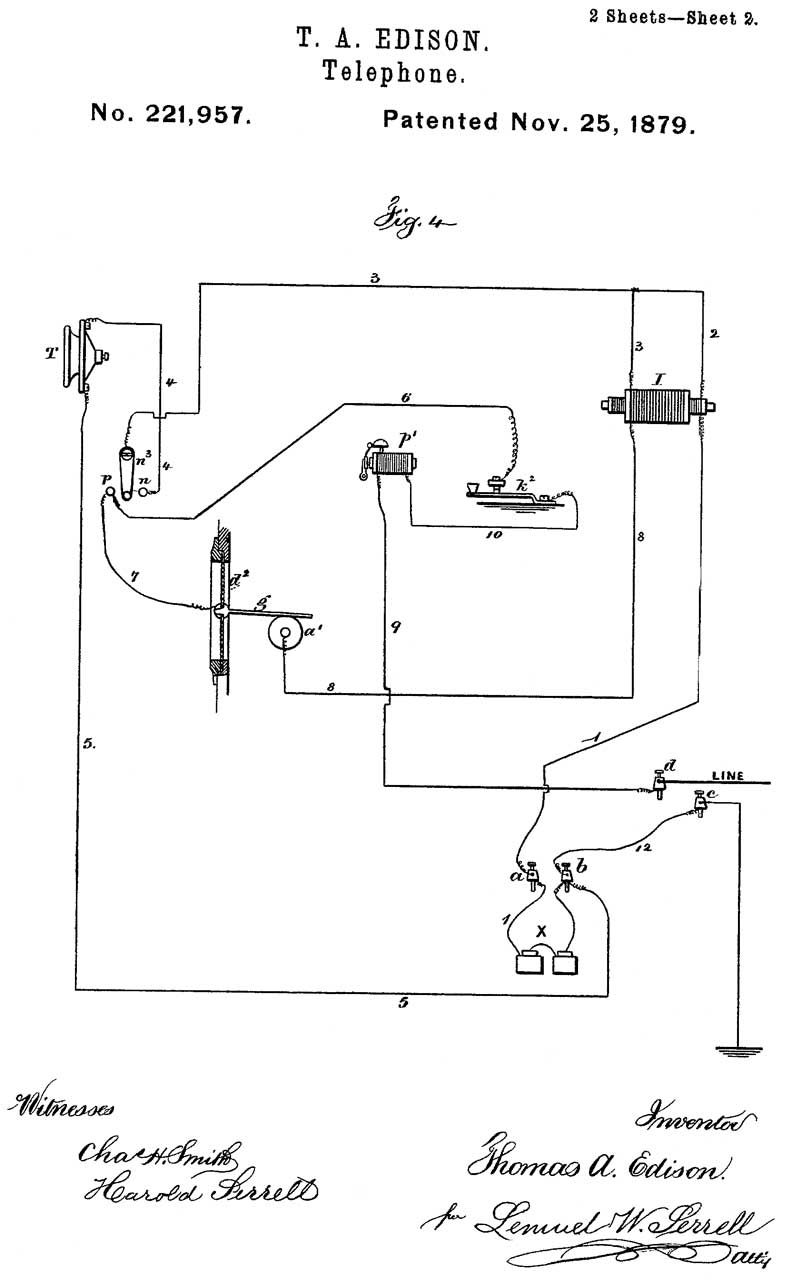
221957 Telephone, T.A. Edison, 1896-11-25, 379/387.01; 192/84.1; 24/132R -
oldest patent in class 379/387.01- I is the Induction (inductorium) Coil
1014780 Spool-head, Charles H Smith, Kellogg Switchboard and Supply Co, 1912-01-16, - works with any coil outside diameter without drilling new holes.
259809 Means for utilizing secondary batteries on telephone-circuits, C.E.Buell, 1882-06-20, 379/387.01 -
199007 Telephone, T.A. Watson (Wiki) 1878-01-08, 379/255 -
This is the oldest patent in class 379/255.

Table
| DC Omhs |
FBtest1 |
SR 715 LCR |
HP
427x LCR |
|||
| 88 mH (connected)
Telephone Loading Coil (Red) |
4 + 4 |
G4 |
87 mH |
200
(10 kHz) 65 (1 kHz) |
||
88 mH (connected)
Telephone Loading Coil (Green)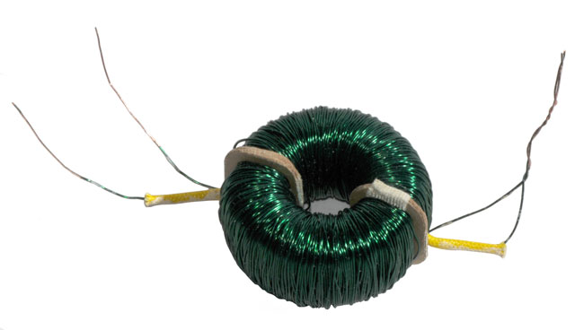 |
4 + 4 |
G4 |
80.6 |
6.3
(10 kHz) 65 (1 kHz) |
||
Three No. 46 Telephone
Induction coils (transformers)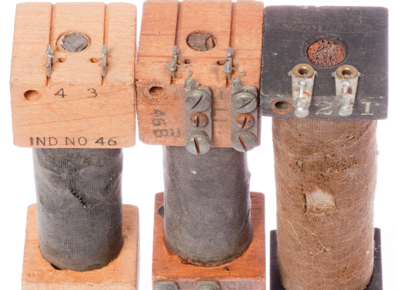 |
||||||
Electromagnets
103231 Electro Magnet, H.M. Paine, 1870-05-17, 336/84R 336/195 336/73 - looks like a nail with wire wrapped on.
RE4237 Electromagnetic Coil, H.M. Paine, 1871-01-24, 336/84R 336/73 336/195 -
362135 Polarized electro-magnet, J.C. Wilson, 1887-05-03, 335/230 -
392385 Electroplated Coil for Electrical Measuring Instruments, E. Weston, 1888-11-06, 324/144 335/299 336/82 336/195 310/194 336/73 336/84R - for meter movements.
452003 Electro-magnet, C.E. Lipe, 1891-05-12, 336/206; 140/71R; 336/192; 336/223; 29/605; 336/190; 242/447.1 - bobbin on iron core.
731741 Electromagnet, W. Baxter Jr, 1903-06-23, 335/265; 335/185; 335/279; 335/273 - contactor
737720 Electromagnet, James Duncan, AT&T, 1903-09-01, 336/192; 242/125.2; 439/889 - mounting pins of classic spool type
931445 Electromagnet-coil construction, Abbot A Low, 1909-08-17, 336/195 29/605 174/117R 174/129R 336/207 428/371 428/389 428/592 428/931 174/115 174/119R 336/206 336/223 428/591 428/609 -
1103530 Electromagnet, Charles C Newburn, 1914-07-14, 335/275; 335/274; 340/396.1 - electric (phone?) bell.
1104077 Electromagnetic circuit-controlling device, William F Smith, WE, 1914-07-21, 335/273; 335/274; 335/276; 335/281 - single coil telephone relay stands on end with 2 electrical coil prongs.
Miscellaneous Patents
486926 Coil for electrical apparatus, Henry C. Buck, 1892-11-29 336/205; 336/206 - each layer coated with "paraffine or other plastic insulator" - No. 46 coils?
669710 Telephone-circuit, Charles E Scribner, Western Electric, 1901-03-12, 379/324 379/391- "My invention concerns the operation of telephone transmitting instruments at substations by means of current supplied over the telephone line conductors from a central point, the windings of an induction-coil and an accumulator, such as a condenser or equivalent device, being associated by peculiar circuits with the transmitting telephone, whereby speech transmission of unusually high efticiency may be attained."
744018 Method of forming coils for electrical apparatus, Edward L Aiken, GE, 1903-11-17, 72/371; 72/137; 29/609 -
795279 Winding-machine, Charles E Hadley, Federal Manufacturing Co, 1905-07-25, 242/483.4; 74/59; 242/486.9 -
1080830 Electrical coil and method of winding same, Max Helm, 1913-12-09, 336/206; 206/389; 242/166; 242/178; 336/209; 242/444.4- basket weave for magnet and resistance coils (not inductors).
1141583 Winding-machine, Claes Ryden, Universal Winding Co, 1915-06-01, 242/480.8; 242/482.7- for wire coils
1203789 Electrical coil and method of winding same, Claes Ryden, Universal Winding Co, 1916-11-07, 336/206; 242/166; 242/178; 336/209; 242/444; 242/447.1 -
1699661 Inductance, George A Freeburg, 1929-01-22, 336/191; 29/605; 336/107; 336/67; 336/208; 336/229; 336/222 -
1806697 Coil winding machine, W.O. Meissner, 1931-05-26, 242/444.5 - multiple parallel coils, fine lacquered wire, wax paper layers
1812349 Coil winding machine, Hoxsie W Lillibridge, Atwater Kent, 1931-06-30, 242/447.2 - cylindrical form
1940228 Radio-amplifying circuits, Wladimir J Polydoroff, Johnson Laboratories, 1933-12-19, 330/169; 330/155; 334/77; 336/206; 336/234; 330/171; 334/61; 336/136; 336/226; 361/298.1 - powdered iron cores
1982689 Magnetic core material, Wladimir J Polydoroff, Johnson Laboratories, 1934-12-04, 336/233; 148/306; 29/608; 106/228; 106/287.18; 252/62.54; 264/325; 428/900; 75/348; 106/253; 106/287.23; 148/104; 252/62.53; 264/DIG.58; 428/402- torodial & pot cores
1978599 Variable inductance device, Wladimir J Polydoroff, Johnson Laboratories, 1934-10-30, 336/136 - movable core of insulated magnetic particles
1978600 Permeability-tuned resonant circuit, Wladimir J Polydoroff, Johnson Laboratories, 1934-10-30, 334/65; 334/75; 334/77; 334/85; 336/87; 336/136; 336/208; 334/76; 334/80; 336/67; 336/90; 336/205; 336/231 -
2014833 Coil winding machine, Robert H Burns, RCA, 1935-09-17, 72/133; 72/142 - Vacuum tube filaments
2059393 Magnetic core for high frequency inductances, Wladimir J Polydoroff, Johnson Laboratories, 1936-11-03, 331/176; 336/155; 336/182; 336/233; 331/167; 336/179; 336/212; 336/234 -
2292182 Loop antenna, Lewis H Van Billiard, GE, 1942-08-04, 343/866; 29/605; 336/205; 336/206; 343/702; 343/842; 174/396 - shielded with deep nulls
2305085 Machine for winding electrical coils, Frederick N Jacob, Martin J Kirk, Johnson Laboratories, 1942-12-15, 242/447.1; 388/824 - cylindrical form, basket weave
5014012 (GB2220756) D.C. biasing apparatus, Yoichi Kuboyama, Koichi Yanagawa, HP, 1991-05-07, - how DC current bias effects inductance - sore saturation measurement method?
Related
HP 4260A Universal Bridge
HP 4274A & HP 4275A LCR Meters
HP 4332 LCR Meter
HP 4395A in Impedance Analyzer mode
Impedance (Z)
Magnets
Marconi TF-2700 Universal Bridge
NZ-1 Coil Winder
Stanford Research 715 LCR Meter
ZM-11 Impedance Bridge
Q-Meters
Crystal Radios
Impedance
Zo of a transmission line
Links
Back to Brooke's Home, Test Equipment, Products for Sale, Military Information web pages.Wires.co.uk - close to every wire known to man.
Page created 19 Jan 2011.