Front Back Foote Phila.
Pat Pend
adjustable Crystal assembly20 mmf Capacitor
Front Back Foote Phila.
Pat Pend
adjustable Crystal assembly20 mmf Capacitor
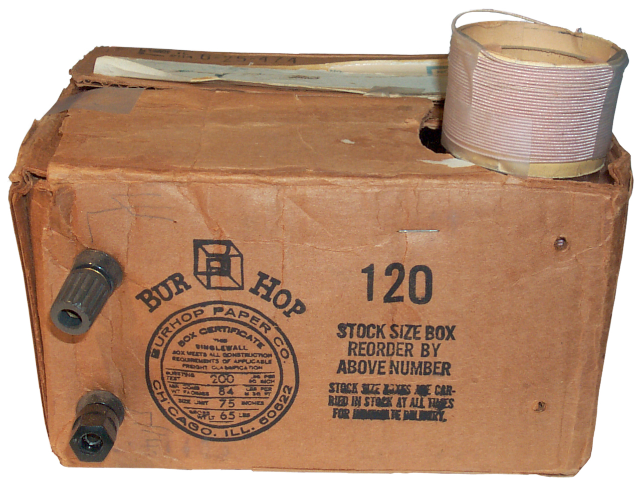
June 2022: UPDATE: This is the NBS Circular 120 Radio. When I started this web page I did not know anything about this Crystal Radio.
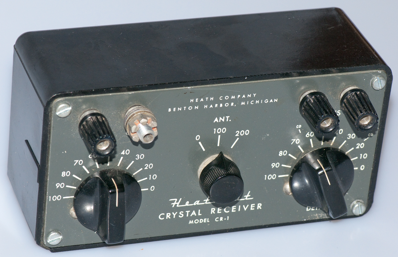
I think this is a home made crystal radio (Wiki) from about1800 (?)1920s. The "Foote Phila. Pat Pend" is an assembly that has a Galena crystal (Wiki) in a lead holder (Wiki: Crystal detector), but it has a threaded rod out the back. On the front panel there is a knob that turns a threaded rod with a Berrillium copper spring that can be adjusted so that it touches various spots on the crystal. I was able to adjust it for 2 volts and 0.9 volts (reverse and forward at 1 mA) using a Fluke 87 DMM.On the upper left corner of the front panel is the ANTENNA connection. The bottom left terminal is GROUND.
On the right lower corner are the PHONES terminals (lower one is ground).The wire appears to be bailing wire or some other Iron wire, not copper.
The front panel terminals use an 8-32 threaded pinch screw with the threaded portion 5/16" long..
I'm looking for 3 of these.
NBS Circular 120 (pdf)
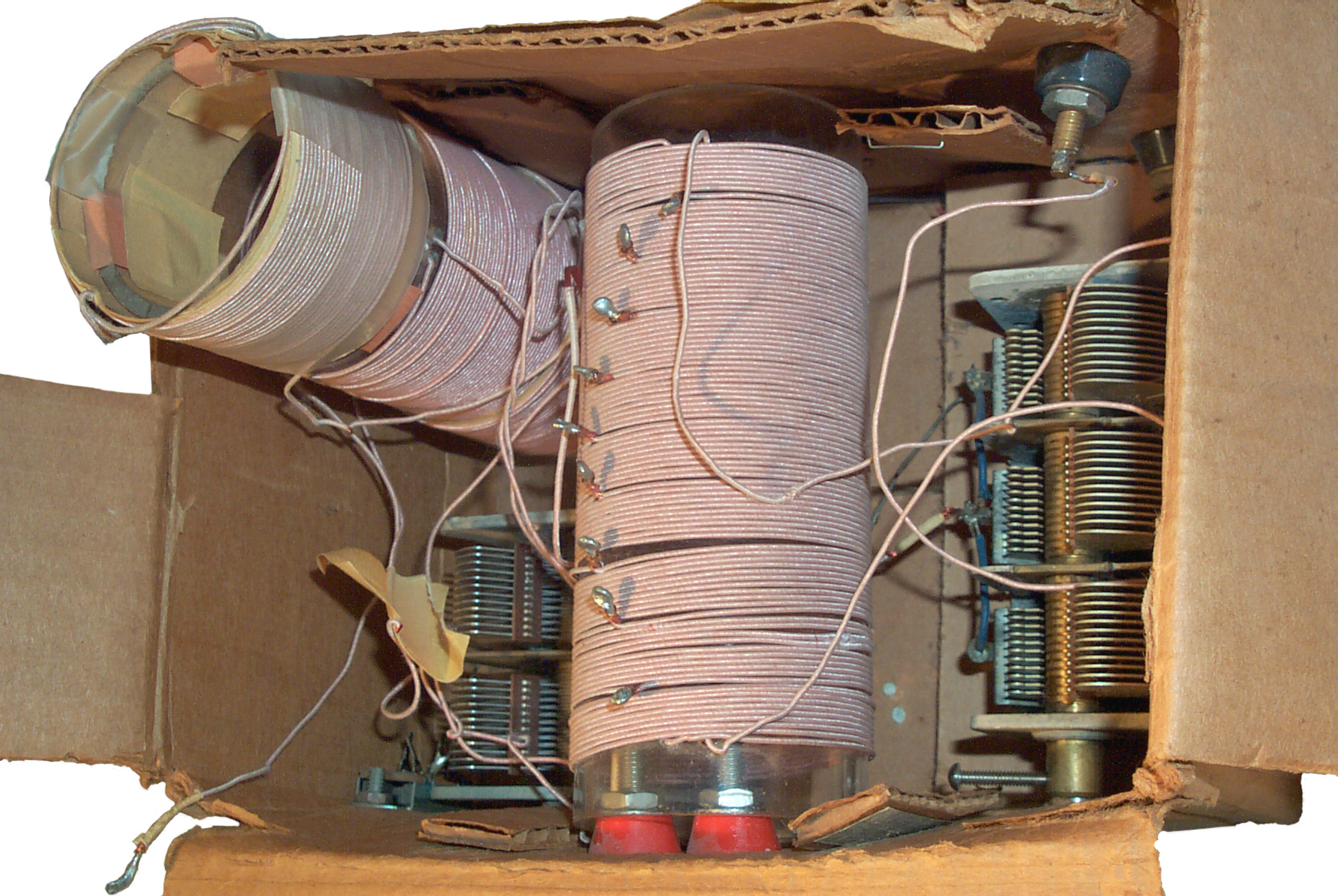
From ANTENNA to PHONES is the diode.
From ANTENNA to GROUND is a coil, where the upper 10 position switch sets coarse taps and the bottom 10 position switch sets fine taps.
From PHONES hot to PHONES ground is a 20 mmf capacitor that looks like a Copper bar with something wrapped around it and maybe some shim stock sandwiched between two thin wood boards.
This matches the NBS circular 120 design.
Page 12 Receiver
This is probably be the NBS Circular 120 radio.
NBS Circular 120: article about Construction and Operation of a Simple Homemade Radio Receiving Outfit (pdf) - Circular 120 (pdf)
Ref: A Century of Excellence in Measurements, Standards, and Technonogy, David R. Lide, NIST, 2002 - pg 16
Galena Holder
879117 Rectifier and Detector, G.W. Pierce, Massachusetts Wireless Equipment, 1908-02-11, 257/613 257/41 252/62.3V 329/370 -
1122358 Detector, Lester Stewart Barr, 1914-12-29, 257/41 -
1104065 Detector for Wireless Apparatus, B.J. Miessner, 1914-07-21, 257/41 -
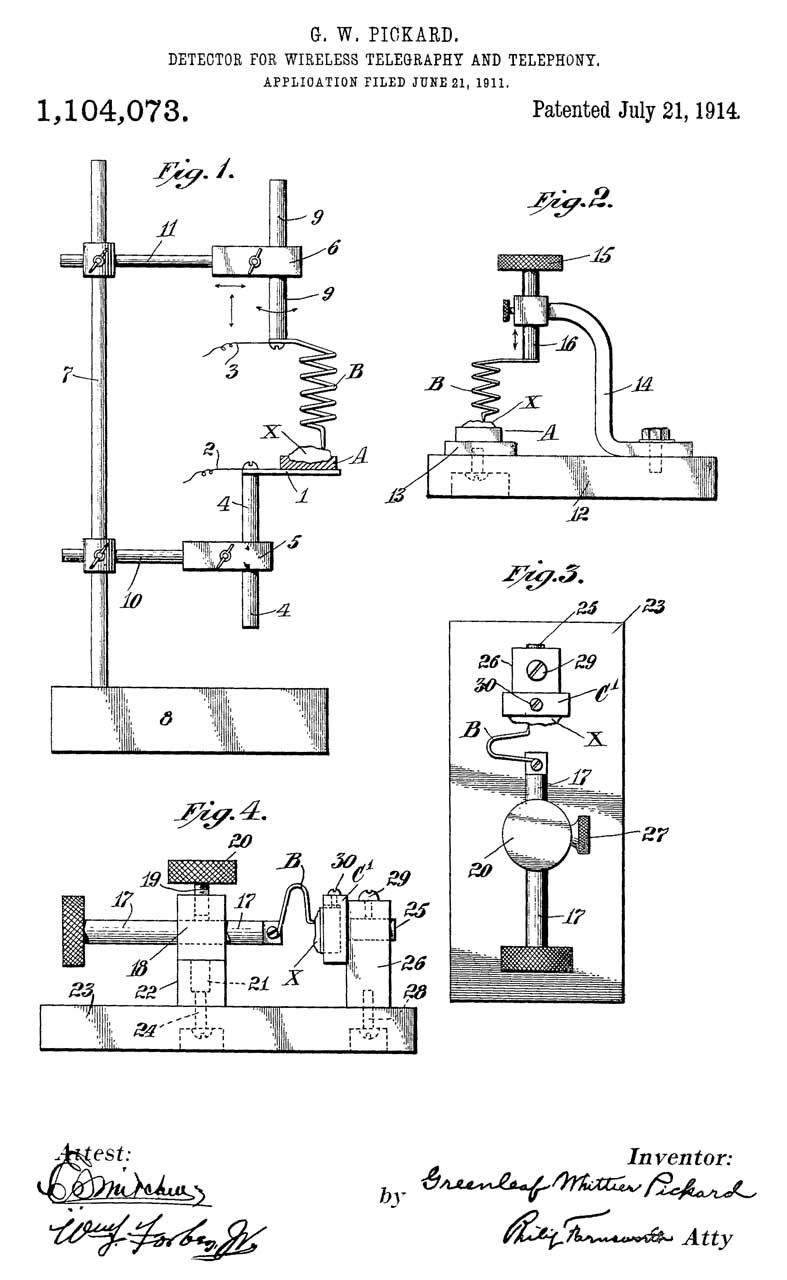
1104073 Detector for Wirlelss Telegraphy and Telephony, G.W. Pickard, Wireless Specialty Apparatus, 1914-07-21
RE13798 Means for Receiving Intelligence Communicated by Electric Waves, G.W. Pickard, 1914-09-08, 329/347 439/8 257/41 403/24 -
1290755 Wireless Detector, S.S. Jones, 1919-01-07, 257/41 439/8 -
1496671 Detector, H. Gernsback, 1924-06-03, 257/41 252/62.3R -
1515994 Oscillation Detector, A.W. Bowman, 1924-11-18, 257/41 -
1576783 Radiodetector, J.B. Pitts, 1926-03-16, 257/41 -
Patents in class 257/41 - published after W.W.II relate to the 1N21 microwave point contact diode.
 |
 |
 |
 |
 |
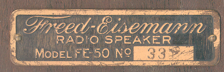 |
331 s/n
stamped in bottom wood in addition to the name plate s/n.  |
 |
 |
 |
 |
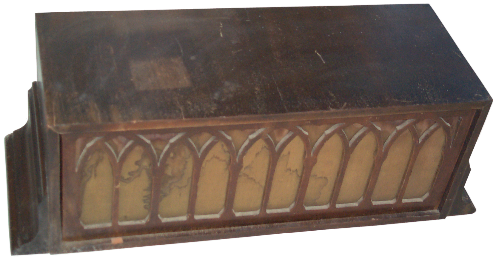
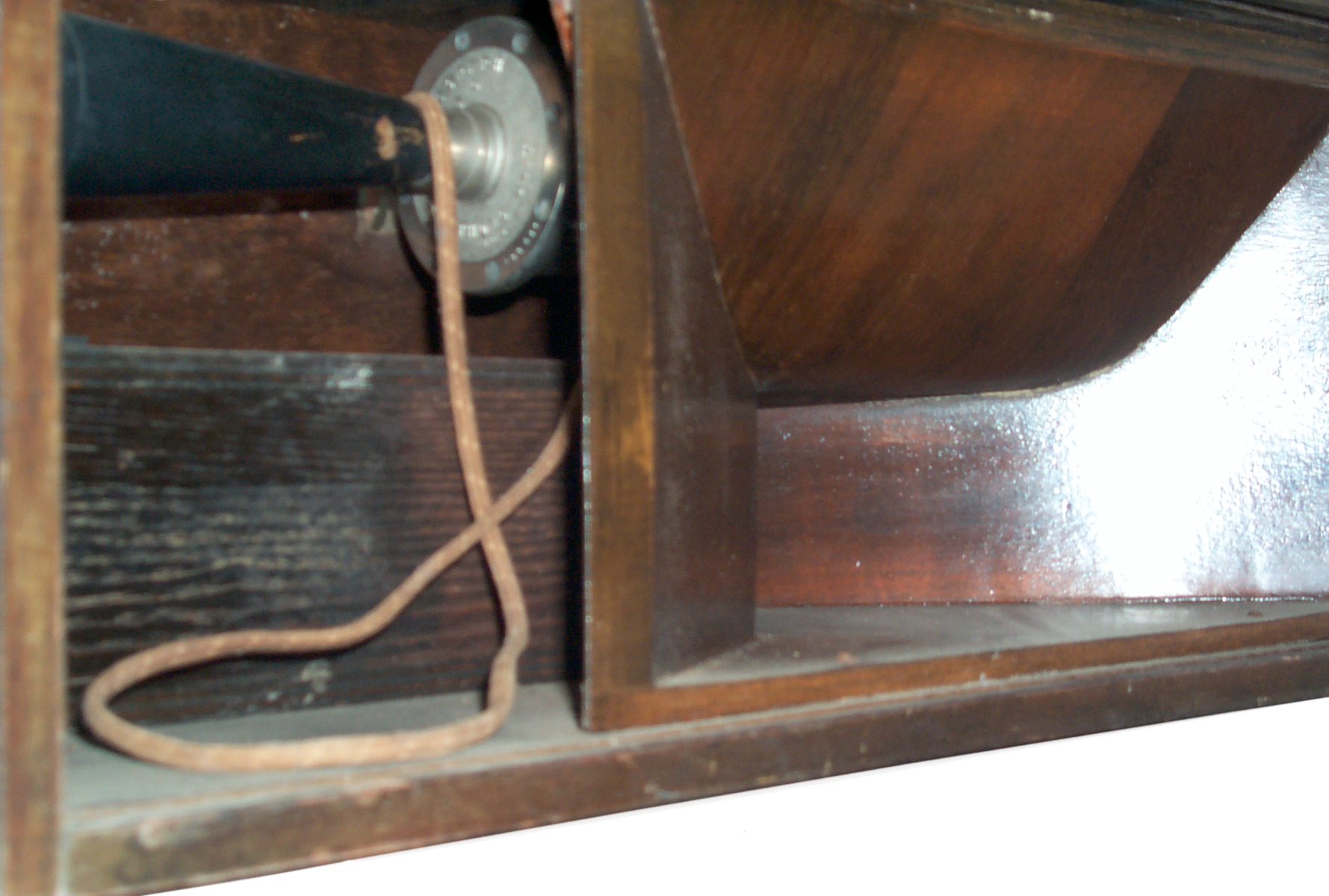
The FE-50 speaker driver above does not use the lever arm type movement from the Sound Powered Telephones, but it still has great sensitivity.
I got this after studying Sound Powered Telephones and the very efficient speaker elements they used. This speaker driver uses a similar if not the same drive method.
Both of the below patents cover it.
957403 Telephone-receiver, Nathaniel Baldwin, May 10, 1910, 381/418 -
1604251 Telephone receiver, Nathaniel Baldwin, Oct 26, 1926, 381/418; 381/419 -
 |
|
W.W. I Army Crystal Radio.
Wiki & EROLS Armstrong, BC-14, have web pages on this crystal set.
A note about Schottky diodes as detectors. When used for microwave detectors, see Aertech Schottky Diode Detectors, a forward bias was applied control the diode impedance to get a good microwave VSWR. I expect for AM radio crystal detectors a circuit that resulted in some forward bias would work better than using the Schottky without any bias. Again biasing a Schottky diode for use in a medium wave AM radio would be to match the diode to the source impedance. The source impedance depends on the design of the radio, specifically the coil driving the diode.
Agilent Technologies Technical Data sheet 5968-7181E (Obsoletes 5968-4304E)
Guard ring diodes are: 1N5711, 1N5712, 5082-2800, 5082-2810 & 5082-2811.
The 5082-2300 series and 5082-2900 series are not guard ring.
Electrical Design
The reason Schottky diodes are used a Switching Mode Power Supplies is not their low Vf, but rather because the reverse recovery time (Wiki) is very short since there are no slow moving minority carriers, only majority "hot" carriers, hence the moniker Hot carrier diode.
Germanium Point Contact
Also see my 1N21 web page for point contact diodes which were used for crystal radios operating at microwave frequencies. Also see my Radar Warning Receivers web page where there are many examples of "Crystal Video" receivers, i.e. microwave crystal radios.
Note a point contact diode is a Schottky diode (Wiki) since by definition it's a metal semiconductor junction. The Cat's whisker is a metal.
Guard Ring Schottky
These are Schottky diodes with an added guard ring that raises the breakdown voltage to around 60 Volts.. See Diodes that do not store charge.
Listed as General Purpose Diodes in the Agilent Technologies Technical Data sheet 5968-7181E
p/n
Vbr
10 uA
Vf
1mA
Cj
pF
Pkg
5082-2800 70
0.410
2.0
DO-15
5082-2810 20
0.410 1.2
DO-15 5082-2811 15
0.410 1.2
DO-15 1N5711
70
0.410
2
DO-15
1N5712
20
0.550
1.2
DO-15 The 5082-2800 comes in a glass package with a "C" bend contact.
These have a couple of down sides.
1. The guard ring adds capacitance so for applications where Cj is important it's better to use a plain Schottky.
2. Sometimes there's an error in fabricating the diode and the Guard Ring ends up storing charge. A very bad thing in a detector diode. This might be called a "double break" or "knee" in the Vf curve.Plain Schottky
In addition to point contact diodes these might include the:
p/n
Vbr
10 uAVf
1mACj
pFPkg Application
5082-2303
20
<0.400
1.0
DO-15 low 1/f flicker noise
5082-2900
10
<0.400 1.2
DO-15 low 1/f flicker noise 5082-2835
passivized
8 (100uA)
.0340
1.0
DO-15 UHF mixer
The plain Schottky diodes seem to have a Vf below 400 mV.
Packages
"S" Bend
This is a true point contact configuration.
3178796 Method and device for the machine assembling of crystal diodes, Smits Willem Frederik, US Phillips, 1965-04-20, -
Probably the package for a real 1N34A?
"C" Bend
Not point contact since the "C" is contacting a very large bump that's plated over the actual diode.
3795045 Method of fabricating semiconductor devices to facilitate early electrical testing, G Dumas, Silec Semi, 1974-03-05, -
Example is the HP 5082-2800
Double Plug
These are very low cost high volume, but have a lot of capacitance. Not at all a point contact.
3271124 Semiconductor encapsulation, James E Clark, Bell Labs, 1966-09-06, -
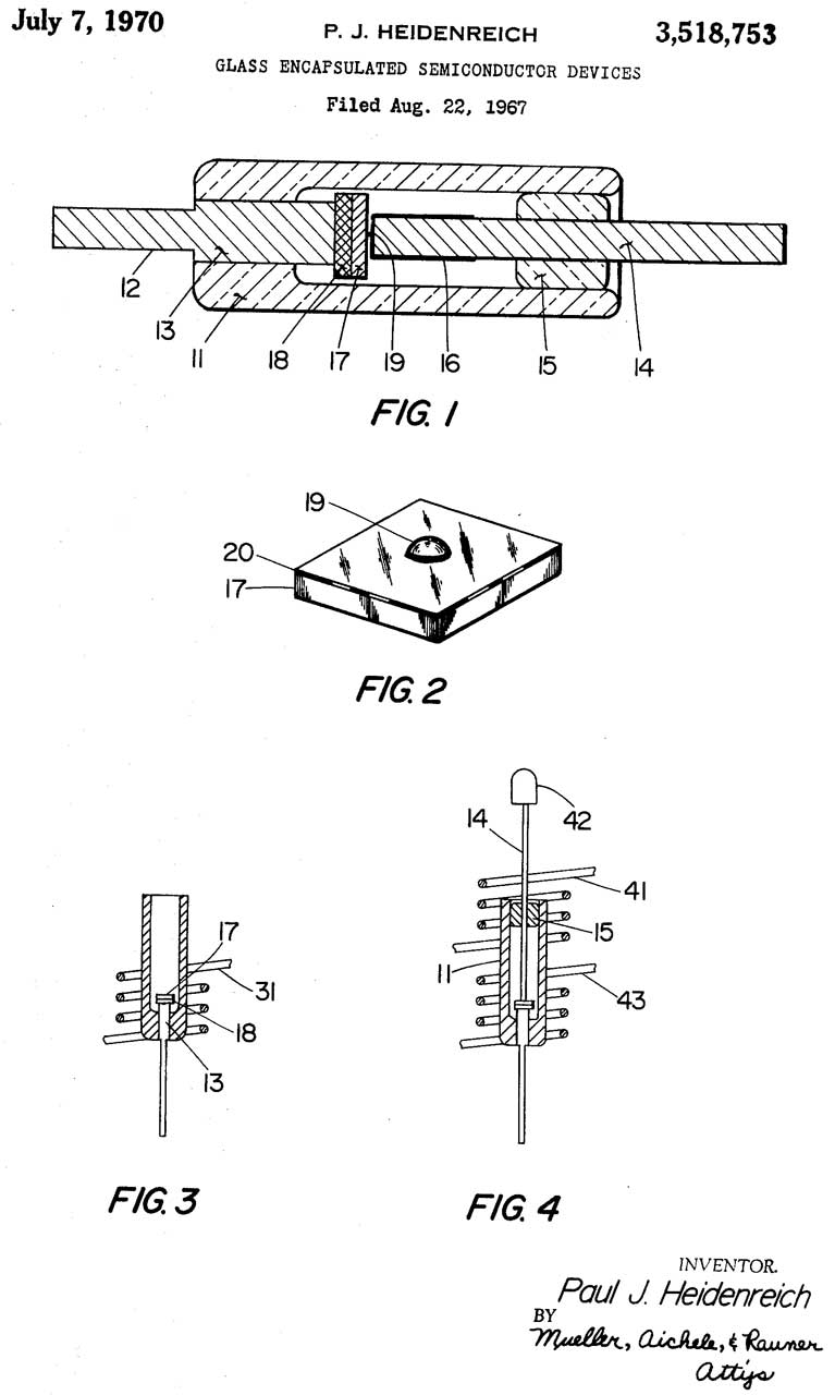
3518753 Glass encapsulated semiconductor devices, Paul J Heidenreich, Motorola, 1970-07-07, - Double Plug glass package
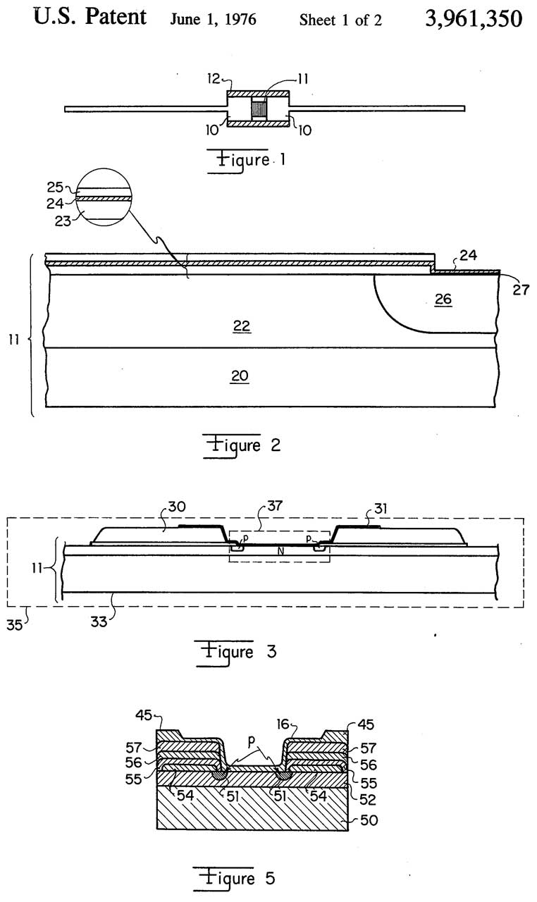
3961350 Method and chip configuration of high temperature pressure contact packaging of Schottky barrier diodes, Karl H. Tiefert, HP, 1976-06-01, - Double Plug DO-35
Examples
Photo
Description
Package
Vf @ If
Vr @ Ir
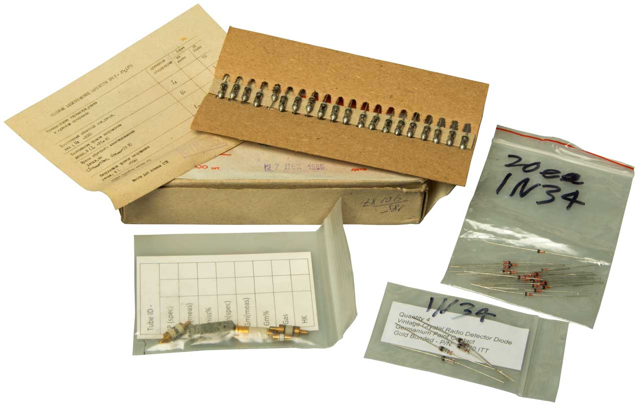
Group Photo CW from upper left:
Ukraine box of 100 IS307
20 ea Double Plug Diodes
4ea 1N270
1N21 Germanium point contact Assortment
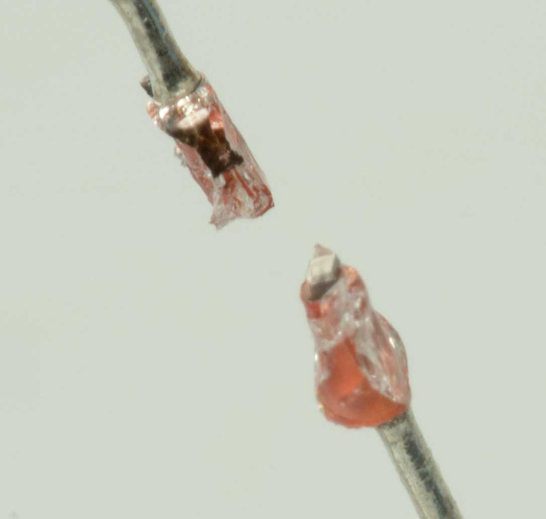
IS307 Germanium Point Contact D18
Double Plug Diode
I have some marked 1N5712 and
others marked 1N34.
The I-V curves for the diodes marked
1N34 & 1N5712 are almost identical
as are their physical packages.
IV Data (1N5712 & 1N34)-01.pdf
The forward curve is fitted up to 2 mA.
Rs is calculated based on the 5mA and 10mA points.
DO-35 275mV @ 1 mA
1N270 Germanium Point Contact DO-7
1000mV @ 200mA
50V @ 100uA
Measuring
The best measurements happen when the forcing function is orthogonal to the device curve. For example to measure the forward voltage (Vf) it's best to use a current source since the device curve is pretty much vertical.
Fig 1 shown with Double plug DO-35 diode, Fluke 87V DMM & Keithley 224 Current Source
Vf @ 1 ma. = 0.275V
Diode Models (Wiki)
A point contact diode is also a Schottky diode.
Marked:
1N34
1N5712
1S307
Forward
Io
5E-08
2E-08
3E-6
Vd/enVt
35.9
33.7
18.4
R2
0.9987
0.9962
0.9681
Rs
7.6
12.6
17.8
Reverse
Rp 10M 10M 30M
R2 0.9864
0.9998
0.9893
1N34 Applications
The use in a Crystal Radio (the main subject of this web page) started this section about Diodes.
YouTube has a large number of videos addressing the "1n34 Germanium diode".
But there are other applications such as:
BDST AF-RF Signal Tracer where the 1N34A is used to detect - demodulate RF.
Guitar Effects Pedals (Wiki: Effects Unit; Klon Centaur, Klon Centaur Analysis)
This is an alternate detector for crystal radios. It's the quasi-zero-volt 3SK143-Q MOSFET.
Silicon N-Channel 4-pin MOS FET.
YouTube: BillyCdiy:3DQ Crystal Radio Module that works for all bands AM, SW and FM, 14:44 -
@0:32 Circuit Diagram for module
Taipei AM Crystal Radio 2019-08-27 (3DQ), 11:34 -
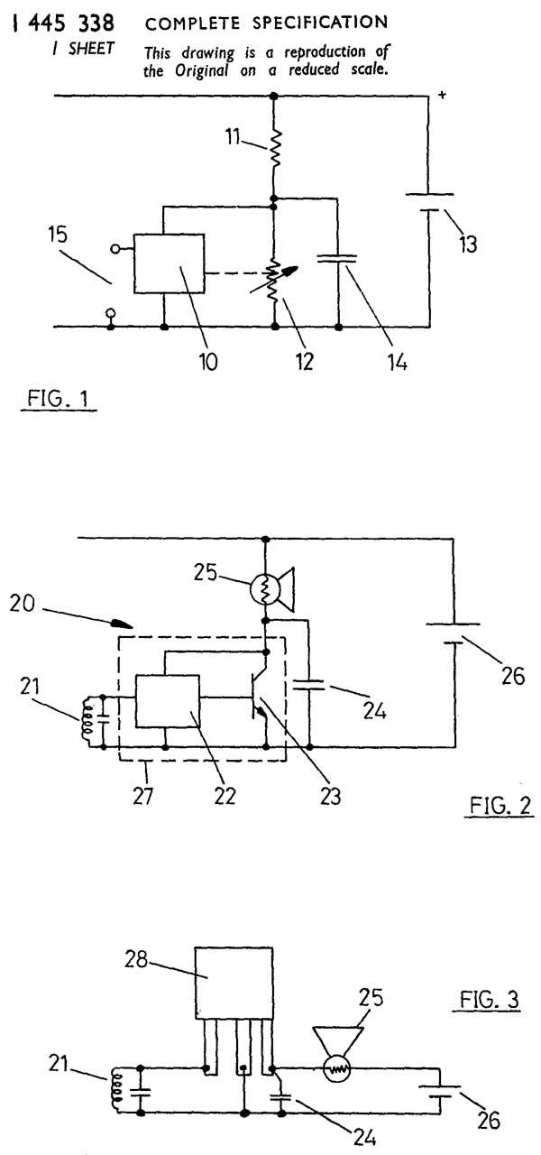
This 3-terminal IC and a small number of external components will make an AM broadcast radio. It needs a 1.5 V battery, but the ZN414 draws less than 500 uA of current so a modern battery like the Energizer L91 AA might last 20 years.
My recollection was that it was touchy, i.e. you need to get everything correct or it doesn't work. The patent says gain is proportional to supply voltage so using a 1.5V battery (that might be 1.6 or 1.7V is a mistake). The patent Fig 3 shows battery (26) as a Mercury button cell battery (Wiki) which has a voltage of 1.35V and is very stable over it's life. Is there a diode that would drop the voltage from a AA battery to 1.35V with the current is less than 500 uA? Let me know.
ZN414 (Wiki) (<1.6V)
aka: YS414, TA7642 (<6V), MK484 (<1.8V), LMF501T-2 (<1.5V)
GB1445338 (eSpaceNet) Automatic gain control circuit arrangements having a plurality of stages of amplification, Ferranti, 1976-08-11, - ZN414
Most of the listed patents are by Pickard.
Also see 1N21 Diode
755840 Detector for electrical disturbances, Jagadis Chunder Bose, 1904-03-29, - galena or tellurium
836531 Means for receiving intelligence communicated by electric waves, Greenleaf Whittier Pickard, 1906-11-20, - Silicon
837616 Wireless-telegraph system, Henry H C Dunwoody, 1906-12-04, -
846081 Receiver, Louis W Austin, National electric Signaling Co, 1907-03-05, - tellurium and silicon or alloys of these metals is especially sensitive
876996 Intelligence intercommunication by magnetic-wave components, Greenleaf Whittier Pickard, 1908-01-21, - loop antennas
888191 Oscillation-receiver, Greenleaf Whittier Pickard (Wiki), 1908-05-19, - almost a cat's whisker detector assembly but no whisker
893811 Electrical condenser, Greenleaf Whittier Pickard, 1908-07-21, - electroplated glass jar
904222 Oscillation-detecting means for receiving intelligence communicated by electric waves, Greenleaf Whittier Pickard, 1908-11-17, - detector assembly
912726 Oscillation-receiver, Greenleaf Whittier Pickard, 1909-02-16, - almost a cat's whisker detector assembly but no whisker
912613 Oscillation detector and rectifier, Greenleaf Whittier Pickard, 1909-02-16, - almost a cat's whisker detector assembly but no whisker
924827 Oscillation-receiver, Greenleaf Whittier Pickard, 1909-06-15, - detector assembly
933263 Oscillation device, Greenleaf Whittier Pickard, 1909-09-07, - detector assembly
963173 Oscillation-receiver, Greenleaf Whittier Pickard, 1910-07-05, - almost a cat's whisker detector assembly but no whisker
972715 Telephone receiving apparatus, Greenleaf Whittier Pickard, 1910-10-11, - two coil headphone type receiver but with adjustment of gap between coils and diaphram
1104073 Detector for wireless telegraphy and telephony, Greenleaf Whittier Pickard, Wireless Specialty Apparatus Co, 1914-07-21, - cat's whisker detector
Much more complicated (expensive) than it needs to be. But has the key elements.
1118228 Oscillation-detector, Greenleaf Whittier Pickard, Wireless Specialty Apparatus Co, 1914-11-24, - almost a cat's whisker detector assembly but no whisker
1245266 Radio telgraphy and telephony receiver, Greenleaf Whittier Pickard, Wireless Specialty Apparatus Co, 1917-11-06, - triple coil electrostatic coupled non-resonant secondary and 1245267
1127921 Apparatus for radio communication, Greenleaf Whittier Pickard, Wireless Specialty Apparatus Co,1915-02-09, - Loose Coupler with many taps
1128817 Valve-detector for wireless, Greenleaf Whittier Pickard, Wireless Specialty Apparatus Co, 1915-02-16, - Edison Effect single tube
1136044 Oscillation-receiving device, Greenleaf Whittier Pickard, Wireless Specialty Apparatus Co, 1915-04-20, - crystal to crystal contact also 1136045, 1136046, 1136047
1137714 Solid rectifier for feeble electric currents, Greenleaf Whittier Pickard, 1915-04-27, - detector assembly
1144969 Radio telegraphy and telephony receiver, Greenleaf Whittier Pickard, 1915-06-29, - Fig 3 resonant antenna coil and coupled resonant coil - Fig 7 adds coupling coil to detector
1156625 Wireless receiving improvement, Greenleaf Whittier Pickard, Wireless Specialty Apparatus Co, 1915-10-12, - uses carbon button telephone microphone as audio amplifier
1176925 Apparatus for radio communication, Greenleaf Whittier Pickard, Wireless Specialty Apparatus Co, 1916-03-28, - built in test by means of a buzzer
1184376 Radio telegraphy and telephony receiver, Greenleaf Whittier Pickard, Wireless Specialty Apparatus Co, 1916-05-23, - triple coil electrostatic coupled non-resonant secondary
1185711 Receiver for wireless telegraphy and telephony, Greenleaf Whittier Pickard, Wireless Specialty Apparatus Co, 1916-06-06, - vibrator instead of detector
1206911 System of radio communication, Greenleaf Whittier Pickard, Wireless Specialty Apparatus Co, 1916-12-05, - resonant receiving loop antenna
1213250 Means for receiving intelligence communicated by electric waves, Greenleaf Whittier Pickard, Wireless Specialty Apparatus Co, 1917-01-23, - almost a cat's whisker detector assembly but no whisker
1224499 Radio telegraphy and telephony receiver, Greenleaf Whittier Pickard, Wireless Specialty Apparatus Co, 1917-05-01, - various electrostatic coupled coils
1225852 Rectifier, Greenleaf Whittier Pickard, Wireless Specialty Apparatus Co, 1917-05-15, - almost a cat's whisker detector assembly but no whisker
1249482 Radio telegraphy and telephony receiver, Greenleaf Whittier Pickard, Wireless Specialty Apparatus Co, 1917-12-11, - resonant antenna coil, but electrostatic coupled non-resonant secondary coil?
1257526 Constant-pressure solid rectifier, Greenleaf Whittier Pickard, Wireless Specialty Apparatus Co, 1918-02-26, - almost a cat's whisker detector assembly but no whisker
1460439 Interference preventer, Greenleaf Whittier Pickard, Wireless Specialty Apparatus Co, 1923-07-03, - mechanical audio filter?
1472341 Reed telephone receiving, Greenleaf Whittier Pickard, Wireless Specialty Apparatus Co, 1923-10-30, - permanent magnet and electromagnet driven by specific audio frequency
1472342 Electromagnetic compass, Greenleaf Whittier Pickard, Wireless Specialty Apparatus Co, 1923-10-30, - Earth Induction Compass using two coils at right angles.
1476102 Optical selection of split mica sheets, Greenleaf Whittier Pickard, Wireless Specialty Apparatus Co, 1923-12-04, - for thickness of mica sheets by means of polarized light causing a color shift
1479315 Electrical condenser and process for making the same, Greenleaf Whittier Pickard, Wireless Specialty Apparatus Co, 1924-01-01, - metal coating of dielectric sheets instead of using metal foil.
1488613 Vacuous electrical apparatus, Greenleaf Whittier Pickard, Wireless Specialty Apparatus Co, 1924-04-01, - instead of using glass for a tube he uses bolt together metal, for high power apps
1492080 Tuning coil, Marti Charles Louis, MARTIAN Manufacturing, 1924-04-29, - strap with ball
1503765 Electrical condenser, Greenleaf Whittier Pickard, Wireless Specialty Apparatus Co, 1924-08-05, - high power potted
1505600 Process and apparatus for the manufacture of electrical condensers, Greenleaf Whittier Pickard, Wireless Specialty Apparatus Co, 1924-08-19, - a stack of mica sheets and metal foil - compressed and sealed with paraffin
1536453 Vernier for tuning reactances, Greenleaf Whittier Pickard, Wireless Specialty Apparatus Co, 1925-05-05, -Air variable capacitor vernier: not mechanical, but rather small capacitance change.
1547666 Industrial composition and process, Greenleaf Whittier Pickard, Wireless Specialty Apparatus Co, 1925-07-28, - sulfur and asbestos fibers high temperature & pressure. Guess: molded condensers.
1555249 Testing apparatus, Greenleaf Whittier Pickard, Wireless Specialty Apparatus Co, 1925-09-29, - for mica sheets used in condensers
1561483 Distinguishing dielectric sheets, Greenleaf Whittier Pickard, Wireless Specialty Apparatus Co, 1925-11-17, - to detect pin holes in mica sheets
1567542 Closed tuned coil or loop aerial, Greenleaf Whittier Pickard, Wireless Specialty Apparatus Co, 1925-12-29, - Crossed loops similar to the PRD-1 Direction Finder receiver.
1650232 Thermionic tube, Greenleaf Whittier Pickard, Wireless Specialty Apparatus Co, 1927-11-22, - separates filament from cathode to allow AC powered filament
1655022 Electrical condenser, Greenleaf Whittier Pickard, Wireless Specialty Apparatus Co, 1928-01-03, - final condenser has stack under compression
1676745 Electrical reactance, and method and apparatus, Greenleaf Whittier Pickard, Wireless Specialty Apparatus Co, 1928-07-10, - grid leak high resistance low capacitance cartridge
1708453 Radio apparatus, Greenleaf Whittier Pickard, Wireless Specialty Apparatus Co, 1929-04-09, - one tube radio in box and uses both wire and loop antennas, convenient for user
1718431 Radio apparatus, Greenleaf Whittier Pickard, Wireless Specialty Apparatus Co, 1929-06-25, - 3D direction finder
1744838 Phonographic machine, Greenleaf Whittier Pickard, Wireless Specialty Apparatus Co, 1930-01-28, - pickup similar to Sound Powered Phone.
1770143 Radio amplifying system, Greenleaf Whittier Pickard, Wireless Specialty Apparatus Co, 1930-07-08, - one tube amplifies three frequencies at the same time
1841628 Electrical condenser, Pickard Greenleaf Whittier, GE, 1932-01-19, - machine with 10 rolls feeding dielectric and foil.
1889568 Universally adjustable radio apparatus for aircraft, Pickard Greenleaf Whittier, GE, 1932-11-29, - gambled dipole - same figure as another patent in this table.
1907571 Radio receiving apparatus, Pickard Greenleaf Whittier, GE, 1933-05-09, - mujltiple loops and verticals for noise reduction and Direction Finding.
1907572 Static neutralizer for radioreceivers, Pickard Greenleaf Whittier, GE, 1933-05-09, - multiple antennas plus switching
1918825 Extreme loading condenser, Pickard Greenleaf Whittier, GE, 1933-07-18, - heat sinking, 10A @ 1.5 MHz (30 kVA, 9 kV)
1938857 Electrical condenser, Pickard Greenleaf Whittier, GE, 1933-12-12, - high power; also 1938858
1946710 Magnetic compass, Pickard Greenleaf Whittier, GE, 1934-02-13, - uses magnetoresistive material like Bismuth or iron nickel alloy See: GE Gauss meter
2026359 Directive receiver, Pickard Greenleaf Whittier, RCA, 1935-12-31, - small aircraft propeller turns loop antenna flexible cable from antenna turns compass rose. depends on manually nulling a lamp.
Ref 1. YouTube: Understanding and Building Crystal Radio Sets (Slides @ Crystal Sets 202) Al Klase, N3FRQ (Crystal Sets, YouTube) 1:17:11
@1:00 A DIY favorite for more than 100 yearsRef 2. Crystal Radio, History, Design, Contesting, David Day, 42:13 -
@2:02 Editorial Comment - millions have been built
@2:29 Marconi 1896 - Coherer drives Morse Inker
@3:51 Patent 7777 - Supreme Court overturned, used Collier Receiver (see: Sound Powered Phones)
@5:34 The Antennas-Ground System -
@7:07 Ground is where you find it.
@8:01 The Mysterious Decibel
@8:54 What Decibels Mean
@9:52 Headphones (WE 509 to work with 600 Ohm phone system: no good for crystal set or vacuum tube)
@11:46 Audio Transducers "2000 Ohm phones, Crystal Earpiece, "Sound-Powered" phones, Modern Earbuds, matching transformer.
@13:07 Balanced-Armature Transducer for More Efficiency - Nathaniel Baldwin Type-C (1910 patent)
@14:04 Headphone Data - Headsets for Crystal Radios - The Sound Powered units are 10 to 15 dB more sensitive than the others, but modern dollar store earbuds, i.e. those with rare Earth magnets are almost as good. An audio matching transformer is needed. - Headphone Testing -
@17:27 Testing the 'Phones - hold one terminal and touch the other to ground - should hear a click
@18:22 What About the Crystal? - Historical
@19:36 Fessenden Electrolytic Detector (Wiki)
@20:18 Greenleaf Whittier Pickard (Wiki) See: 836531, ..., 1225852
@21:19 Choosing a Detector - pick the one that works best in a radio
@22:36 Active Rectifiers - 3DQ MOSFET (3SK143-Q) with two antennas, or tapped loop antenna - Billy's DIY Dream Shop -
@24:13 Let's Build a Radio! - simiplest= Antenna, Ground, diode & headset.
@25:00 Add a Tuned Circuit - coil resonates the antenna capacitance - does not work that well - if the sliding contact shorts a turn that hurts the Q of the coil.
@26:01 What's Mission? - variable capacitor - can get from All American Radio
@27:01 The Old Standby - brain dead dumb circuit - Crystal Set Design 102: Typologies & the importance of impedance matching
@27:33 Impedance Matching -
@29:26 A better solution with: Impedance Matching -
@32:32 The Den 2 Set - ca. 1990 -
@34:11 The Den 2 Set - ca. 1997 - Published by Crystal Set Society
@35:09 The Pretty Good Crystal Set -
@36:01 NJARC 2006 Crytal-Set Clinic - how to wind coil on 4-1/2 PVC coupling
@36:45 Effective Air-core Coils - Winding length = 2.5 x diameter - space 1 wire dia. - Styrene or ABS better than PVC - Coil Wisdom - Amidon mix 61 cores, like the FT-82-61 (4 ea: $11 including shipping eBay)
@40:24 Joe Devonshire 2021 - excellent performance
@41:00 A Fancy PGXS - Pretty Good Xtal Set -
@41:30 Ferrite Cores
@43:45 Build Small Radios - Crystal Set Mobile - when using piezo phones add 68k parallel resistor for DC crystal circuit.
@45:48 My Living room Set - use in city where there are many strong stations
@46:56 The "Benny" Resistor - adding a series parallel RC (1uF & 68k) circuit to the audio transformer (Triad JAF-3)primary to unload the crystal.
@49:10 The Skywaves Pocket Mouse - Traveling with a Crystal Set -
@49:32 Transformer Wisdom -
@50:07 Microphone Input Transformer: Triad A-11J, UTC O-1
@50:24 Line-to-Voice-Coil Transformer: Speco T7010, Realistic 32-1031
@50:41 Currently Available Transformers - Tamura MER-01, KPB-02
@52:03 High Performance Really Good Crystal Sets - Double-Tuned Circuits - Marconi 101 (ca 1913)
@52:59 The Two-Circuit Tuner - Marconi 7777 patent
@55:57 Double-Tuned the Easy Way: Build a second PGXS! -
@57:23 N3FRQ Contest Crystal Set - Ultra hi Q coils - not sure it does much good?
@59:57 SkyWaves HP-002 - The Skywaves High-Performance Crystal Set -
L1 is 75 turns of #26 enameled wire on an FT-82-61 core tapped every 15 turns. Inductance is approximately 400 uH maximum.@1:02:45 Skywaves Portable (ca 2010) - Traveling with a Crystal Set -built in tackle box. - using "Benny" resistor for S-meter
L2 is 25 turns of #30 on an FT-37-61 core tapped at 3, 10, 15, and 20 turns. Inductance is approximately 35 uH maximum.
L3 is 68 turns of #26 on an FT-82-61 core. Inductance is approximately 290 uH
@1:04:24 One more N3FRQ design: The Jersey City Special - based on W.W. I Telefunken Crystal set (Blueprints)
@1:06:30 Lyonodyne Version 17 Crystal Set - Mike Tuggle - Designing a DX Crystal Set.pdf - adjustable "Benny" resistor, headphones: US Instruments Corp. (USI) are preferred.
@1:07:52 A Beginner's Crystal Set for the Antique Radio Guy - PGXS - based on an All American 5 Tube radio. - Schematic -
@1:09:33 Build a Crystal Set! It's good for your karma!
@1:09:42 Questions: Not impressed with Heathkit CR-1; Vacuum Tube diode, Good Sets: Aeriola Jr, (YouTube); BC-14 W.W.I; 365 uH cap goes with 250 uH air coil & with ferrite you can use smaller cap and more inductance.
@00:19 Experienced ham operators can learn from it too.Ref 3. Your First Varactor Tuned Crystal Radio, 22:46 - @19:51 schematic: dual NTE618 (need for modern variable cap)
@01:39 For those too yhoung to remember crystal radios.
@03:35 Before the diode, Galena crystals (lead sulphide) and 'cat's wiskers' ruled.
@05:17 The Bureau of Standards and oatmeal boxes - NBS120 -
@07:21 The basic circuit is the same as what is in every transceiver
@09:54 Selectivity Vs Sensitivity tradeoff issues spurned a lot of research and development in crystal radio circuitry
@11:26 Overcoming the problems inherent to inefficies of the Crystal Radio
@12:04 Managing interference from strong stations
@15:00 Tapping the induction coil modifies impedance... but changing theinductance value also detunes the L-C circuit
@17:53 What are your goals with grounding?
@19:18 Which method provides the best ground?
@20:14 Diodes
@20:29 Diode Biasing
@26:02 Toroids as cores for coils
@28:30 L-C Series coil configuration with a variable capacitor 20-500pF
@29:53 Selectivity Enhancement Circuits - for those times when you just can't separate 2 close stations.
@32:54 Construction tips
@34:16 Operating tips
@35:15 Lee DeForest and the Audion tube ALMOST completely relegated the crystal radio to 'toy' status.
@ 39:17 Contesting the AM band
@40:21 My 2022 Contest rig: The Toroidyne
@41:00 How well did it work?
@20:13 diagram of coil - 2" dia coil former xRef 4. Our Own Devices: Parallel Tuned Circuits /LC Resonators Crystal Radios: No Batteries? No Problem!, 25:05 -
Primary: 15T #26
Secondary: 10T #26, Tap up from gnd 25T
427uH resonated at 700 kHz (unloaded).
Ref 5. tsbrownie: Crystal Radio--Tips For Using A Cat Whisker (4K), 4:42 - he has lots of Crystal Radio related experiments
Ref 6. glasslinger: Testing Diodes for Crystal Radios, 42:21 - 1 & 10 MHz, no bias and optimum bias (500 Ohm pot from 1 V); chart @39:36. 100uH input choke, 100k load. - The Schottky with bias may be the best?
Ref 7. 2 ways to test germanium diodes 1N34A 1N60 for real vs fake Schottky counterfeits, 3:58 - component testers or @3:14 sine wave to scope.
Ref 8. Are Elusive Magic Diodes REAL? Germanium Diode Overdrive Tone With 9 Vintage Japanese Diodes [1N34], 19:59 - 14:36 Done for guitar effect pedal (Wiki) About the diodes:
Ref 9. Basics of Reverse Recovery Time in a Diode, 12:10 - includes 1N914, 1N5711.
p/n
Vf
Mfg
Construction
SD13
0.27
NEC
S
1S1008
0.29
JRC
?
1S79
0.30
Hitachi
?
ED60
0.32
?
?
1S426
0.32
Sanyo
S
1S188
0.35
Sanyo
S
1K34
0.36
Rohm
S
1N34
0.39
Hitachi
S
SD46
0.49
NEC
?
Crystal Radios - general info & Q of coils
Crystal Clear: Volume 1 by Maurice L. Sievers
Crystal Clear: Vintage American Crystal Sets, Crystal Detectors, and Crystals: Volume 2 by Maurice L. Sievers;
crystal-radio.eu -
The Xtal Set Society -
Wiki: Crystal radio
Gollum´s Crystal Receiver World - Crystal Set Testing
Spark Museum: US Crystal Radios -
Techlib.com: Crystal Radio Circuits -
Peebles Originals - Links -
Jim's Crystal Radio Page - links at bottom of page
Back to Brooke's PRC68, Alphanumeric index of web pages, Products for Sale, Telephones, U229 Audio Accesories, Audio Connectors, Military Information, Electronics, Personal Home page
page created 17 Nov 2001.