One Tube Radio
© Brooke Clarke 2010 - 2025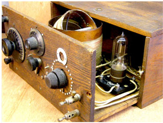
Background
Edwin Howard Armstrong
Lee De Forest
Description
Patents
Related
Tube History
UV-201 Tube
WD-11
Audion
Charles Eisler
Reflex Receiver
Battery Eliminators
Unipotential Tubes
SCR-57 WE Aircraft Interphone
SCR-59 1918 WE 3 Tube radio
VT-1 Tube
WE 396A Chest Horn Carbon Microphone
SCR-68
Links
Background
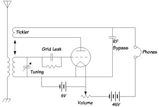
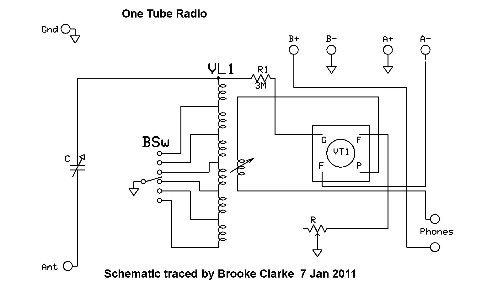
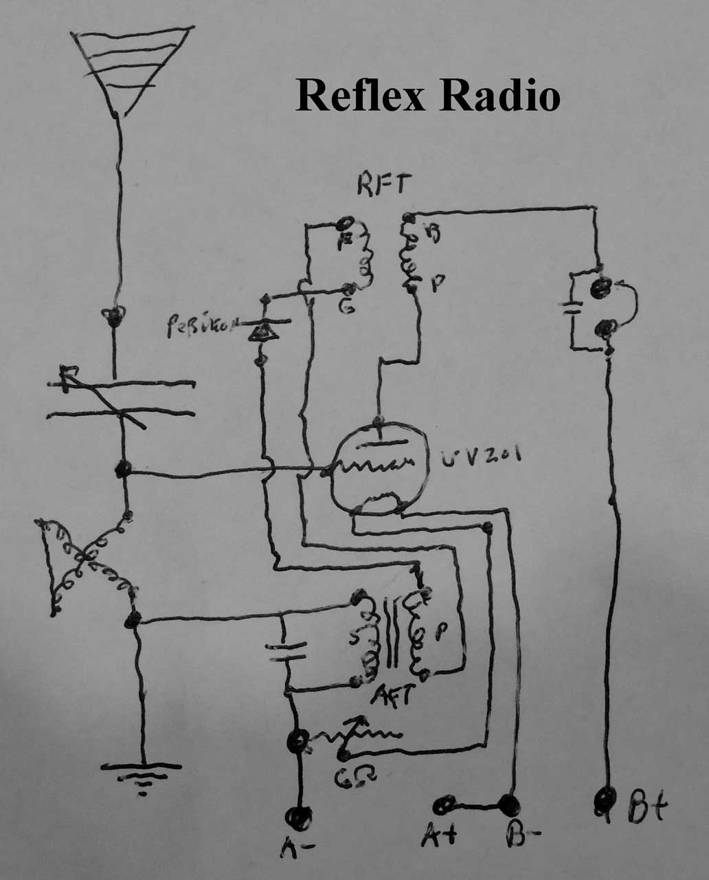
(2014) The below schematic has an error. The Volume pot is in the filament circuit not the B+ circuit.
Edwin Howard Armstrong (Wiki,
EROLS)
Lee De Forest (Wiki)
Description
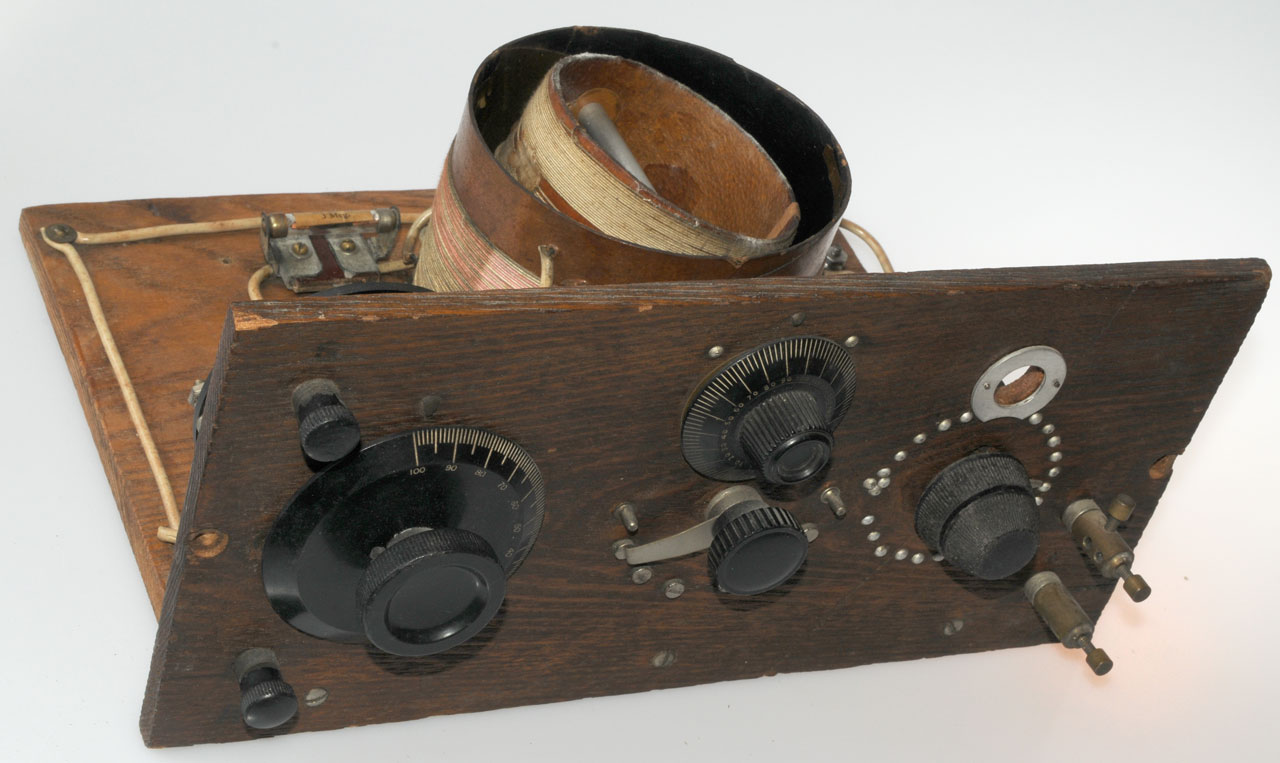
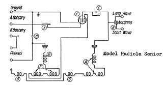
The major components are:Variometer coil with 6 taps - top center dial rotates internal coil, lower center switch selects taps. The movable coil controls the regeneration.
6 Position Switch - controls the tuned frequency along with the variable cap.
Filament Rheostat - controls tube emission (early tube had wide varations in their gain.
It has two concentric shafts and two knobs, a coarse and fine knob.
Only two electrical terminals.
1672290 Potential-Control Apparatus, H.J. Wiegand (Cuttler-Hammer Mfg Co), Jun 5 1928, 338/134 ; 338/150 -
Radiola WD tube socket - for WD-11 or equivalent tube.
1913766 Method and Apparatus for Testing Audion Tube Circuits and Devices, J.H. Miller, Jun 13 1933, - Tube Tester
8 Terminals (2 more terminals used for internal wire connections)
1 & 2: Phones
3 & 4: Antenna and Ground
5 & 6 Filament "A" battery (at rear)
7 & 8: Plate "B" battery (at rear)
 |
 |
Schematic
It's not clear if the antenna and ground are reversed. The metal on the back of the front panel is connected to the upper terminal.
Patents
347 AM
367 Including regenerative feedback in non-oscillating demodulator
Class 375 Pulse or Digital Communications
316 Receivers
338 Interrupted Carrier Wave
339 Carrier Controlling Local Generator
Class 455 Telecommunications,
130 Receiver or Analog Modulated Signal Frequency Converter,
334 With particular receiver circuit,
336 Super-regenerative detector or discriminator
803684 Instrument for converting alternating electric currents into continuous currents, John Ambrose Fleming, Marconi Wireless Telegraph Co, 1905-11-07, - diode tube
841387 Device for amplifying feeble electrical currents, Lee De Forest, 1907-01-15, - triode & other stuff
879532 Space Telegraphy, Lee De Forest, Feb 18 1908, 329/368 ; 313/293; 315/355; 336/220 - Triode Vacuum Tube called an Audion at the time.
1507017 Wireless Telegraph and Telephone System, Lee De Forest, Sep 2 1924, 370/339 -
There was a lawsuit between De Forest and Armstrong and De Forest won the suit (The Complete De Forest- Litigation)
The 1923 Crosley Harko ACE is marked "Manufactured under Armstrong U.S. patent 1113149" as is the Crosley Model 51.
Oldest patent in class 455/336
1415845 Selectively Opposing Impedance to Received Electrical Oscillations, M.I. Pupin & E. H. Armstrong, May 9 1922, 455/282 -
1416061 Radoreceiving System having High Selectivity, M.I. Pupin & E. H. Armstrong, May 16 1922, 375/338 ; 307/105 -
1424065 Signaling System, E. H. Armstrong, July 25 1922 (filed June 27 1921), 455/336 ; 329/359; 329/368; 329/370 -
Second oldest patent in class 455/336
1539821 Wave Signaling System, E. H. Armstrong (Westinghouse Elec), June 2 1925, 455/336 - two tube adjustable Super Regenerative
1611848 Wireless Receiving system for Continuous Waves, E. H. Armstrong (Westinghouse Elec), Dec 21 1926, 375/338 -
1502875 Tone Producing Radioreceiver, M.I. Pupin & E. H. Armstrong (Westinghouse Elec), July 29 1924, 375/339 -
1472583 Method of Maintaining Electyric Currents of Constant Frequency, W.G. Cady (RCA), Oct 30 1923, 331/163 ; 330/112; 331/158; 331/159; 331/164
Fig 1 is the Armstrong circuit.

RCA 1922 Radiola Senior one tube radio patent dates:
Nov 7, 1905
Jan 15, 1907
Feb 18, 1908
Oct 6, 1914
May 10, 1921
Given the list of patent dates above the following may be the corresponding patents:
803569 Induction-Transformer for Wireless-Telegraphy Receiving-stations, Eugene Ducretet, Nov 7 1905, 455/292 - uses coherer and battery (not tube) -although not a regenerative radio, it's very close to the circuit,
804190 Instrument for Making Electrical Measurements, J.A. Fleming (Marconi), Nov 7 1905, - not the circuit, but interesting
841386 Wireless Telegraphy, Lee De Forest, Jan 15, 1907, 315/94 ; 313/147; 313/152; 313/157; 313/161; 313/581; 315/348; 315/349; 315/357; 329/322 - one tube
879532 Space Telegraphy, Lee De Forest, Feb 18 1908, -329/368 ; 313/293; 315/355; 336/220 one tube radio without feedback
1113149 Oct 6, 1914 (see 1113149 Armstrong patent above)
1377405 Audion Circuit, Lee De Forest (De Forest Radio Telephone & Telegraph), May 10 1921, 330/103 ; 330/109; 330/185 - dual triode with feedback
2026758 Secret signaling, Alfred H Turner, RCA, 1936-01-07, - uses FM modulation where the AM modulation is near zero, so an AM receiver will not hear it. Turner has many patents related to UHF equipment.
Related
Brooke"s High Q Crystal Radio
Goof Proof Regenerative Receiver, 73's Nov 1990 - PCB from FAR Circuits
ARRL - High Performance Regenerative Receiver Design by Charles Kitchin, N1TEV, QEX Nov/Dec 1998, pg 24-36 - PCB from FAR Circuits
The New Radio Receiver Building Handbook by Lyle Russell Williams
4 Pin to 7/9 Pin Adapter Kits - allow using a 7 or 9 pin standard glass tube.
Substitutes for the WD-11 - with 4-pin base drawing
Tube History
Wiki: Vacuum Tube History and Development
This comes from the paper:A History of U.S. Navy Periscope Detection Radar: Sensor Design and Development, Shannon & Moser, 2014.
Also see Periscope.
UV-201 Tube (UV201.com)
Patent Dates from Radiotron UV-201 box. Manufactured by Westinghouse for RCA.
1905-11-07
803684
1907-01-15
841387 Device for amplifying feeble electrical currents, Lee De Forest, 1907-01-15, -
1908-02-18
879532 - Audion
1910-04-12
954619 Instrument for detecting electric oscillations, John Ambrose Fleming, Marconi Wireless, 1910-04-12, -
1912-02-27
1018500 Forming device for metallic filaments, Henry W Jackson, Westinghouse Lamp Co, 1912-02-27, -
1912-04-02
1913-12-30
1914-07-28
1915-05-18
1916-10-31
1203495 Vacuum-tube, William D Coolidge, General Electric, 1916-10-31, - X-Ray
1917-10-23
1918-06-04
1918-07-23
1918-12-17
1919-02-18
WD-11 Tube (Wiki)
Patent dates from a WD-11 box. I suspect none of them are applicable to the WD-11, but some might be. They are Westinghouse patents up to 1919.
1905-11-07
1907-01-15
1908-02-18
1910-04-12
1912-02-27
1018500 Forming device for metallic filaments, Henry W Jackson, Westinghouse,
1912-.4-02
1913-12-30
1914-07-28
1915-05-18
1916-11-31
1918-06-04
1918-12-17
1169422 Thermionic Repeater, Alexander M. Nicolson, Western Electric,
RE14572 Thermionic Repeater, Alexander M. Nicolson, AT&T,
1919-02-18
1294694 Electrode for vacuum discharge devices, Henry J Nolte, GE
De Forest Audion (Wiki) 1912 - 1914
After looking at some of the comments in the book Chip War by Chris Miller (Wiki) I'm adding some information here.
824637 Oscillation-responsive device, Lee De Forest, 1906-06-26, -
824638 Oscillation-responsive device, Lee De Forest, 1906-06-26, -
836070 Oscillation-responsive device, Lee De Forest, 1906-11-13, -
836071 Oscillation-responsive device, Lee De Forest, 1906-11-13, -
837901 Wireless telegraphy, Lee De Forest, 1906-12-04, -
841386 Wireless telegraphy, Lee De Forest, 1907-01-15, -
841397841387 Device for amplifying feeble electrical currents, Lee De Forest, 1907-01-15, -
867876 Oscillation-responsive device, Lee De Forest, George K. Woodworth,1907-10-08, -
867877 Art of detecting oscillations, Lee De Forest, George K. Woodworth, 1907-10-08, -
867878 Oscillation-detector, Lee De Forest, George K. Woodworth, 1907-10-08, -
879532 Space telegraphy, Lee De Forest, De Forest Radio Telephone Co, 1908-02-18, -
943969 Space telegraphy, Lee De Forest, De Forest Radio Telephone Co,1909-12-21, -
979275 Oscillation-responsive device, Lee De Forest, De Forest Radio Telephone Co,1910-12-20, -
995126 System for amplifying feeble electric currents, Lee De Forest, De Forest Radio Telephone Co,1909-12-21, -
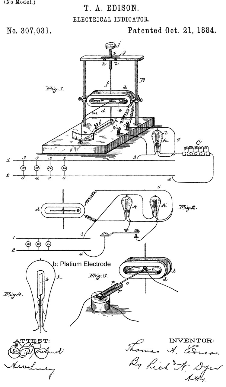
307031 Electrical Indicator, Thomas A. Edison, Oct 21, 1884
Adds another electrode to an electric lamp and notices how it works.
First patent for an electronic device.
"I have discovered that if a conducting substance is interposed anywhere in the vacuous space within the globe of an incandescent electric lamp, and said conducting substance is connected outside of the lamp with one terminal, preferably the positive one, of the incandescent conductor, a portion of the current will, when the lamp is in operation, pass through the shunt-circuit thus formed, which shunt includes a portion of the vacuous space within the lamp, This current I have found to be proportional to the degree of incandescence of the conductor or candle-power of the lamp."
The anode current depends on the filament power. Note in vacuum tubes the filament power needs to be about the same as the anode power. So one of the big advantages of the transistor is that is has no filament and so can be about twice as efficient as a vacuum tube.
Note 1884 is prior to the 1888 early patents on commercial electrical meters hence the home brew looking meter in this patent.
803684 Instrument for converting alternating electric currents into continuous currents, John Ambrose Fleming, Marconi Wireless Telegraph Company Of America, Filed: Pub: Nov 7, 1905 - this patent is for a radio telegraph receiving device.
Fleming Valve (rectifier)
879532 Space telegraphy, Lee De Forest, Forest Radio Telephone Co, Feb 18, 1908
De Forest adds a grid to the tube and calls it the Audion. His two prior patents 824637 & 836070 used Fleming valves (i.e. no grid).
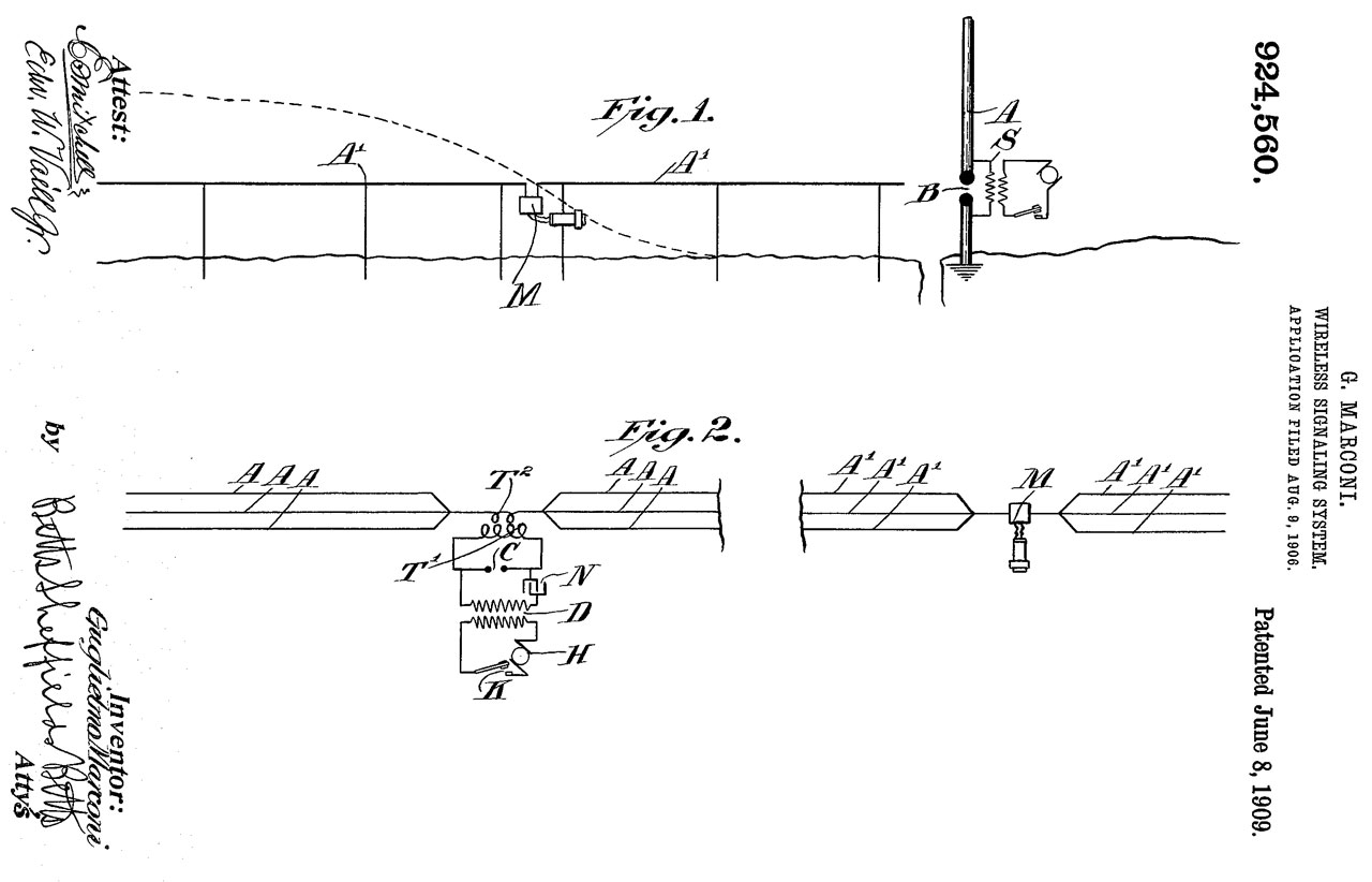
924560 Wireless signaling system, Guglielmo Marconi, Marconi Wireless Telegraph Company Of America, Jun 8, 1909
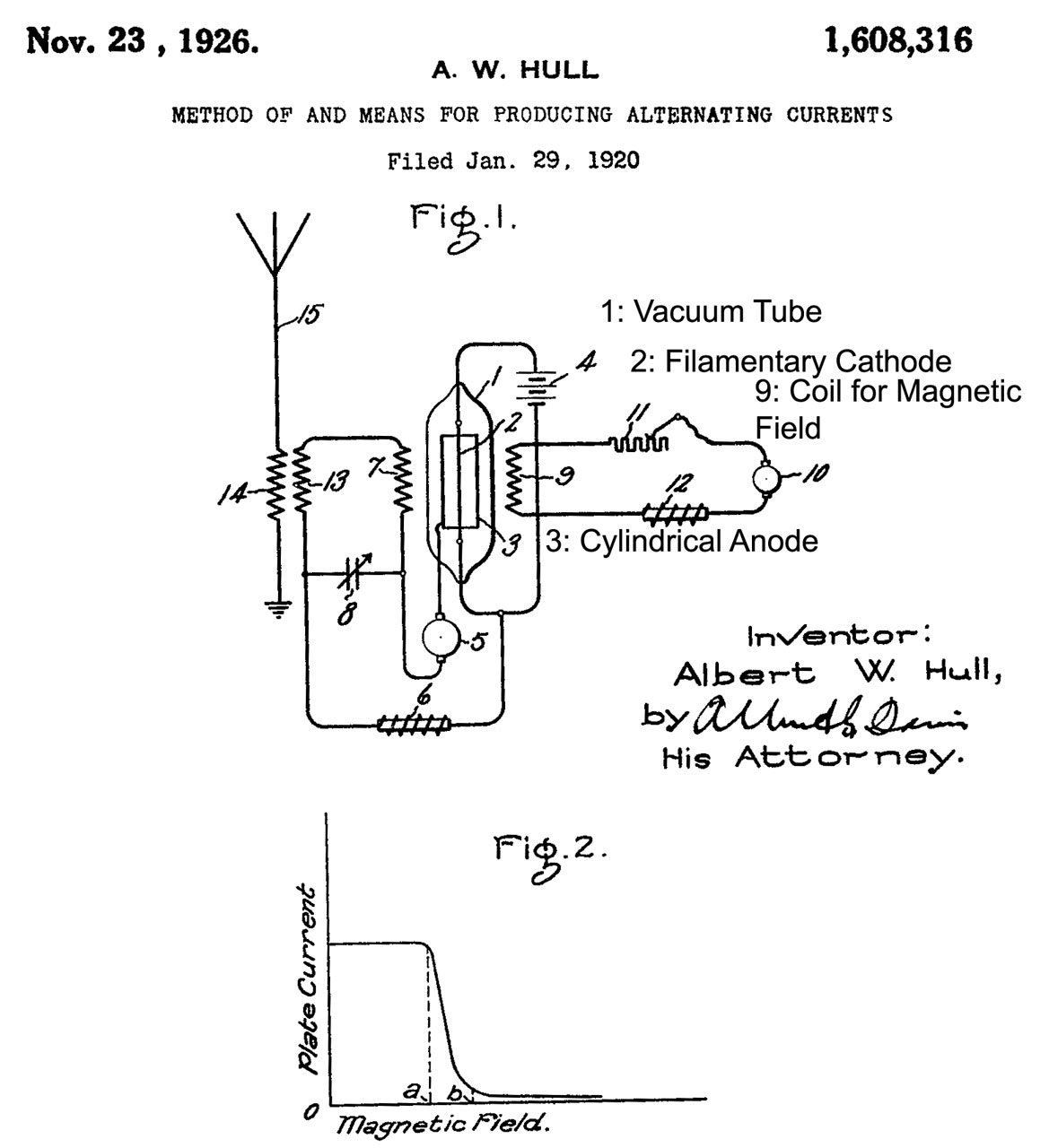
1608313 Method of and means for producing alternating currents, Hull Albert W, Gen Electric, Nov 23, 1926
two-pole magnetron (15 kW @ 20 kHz)
Gets around prior patents by using magnetic filed to control tube current.
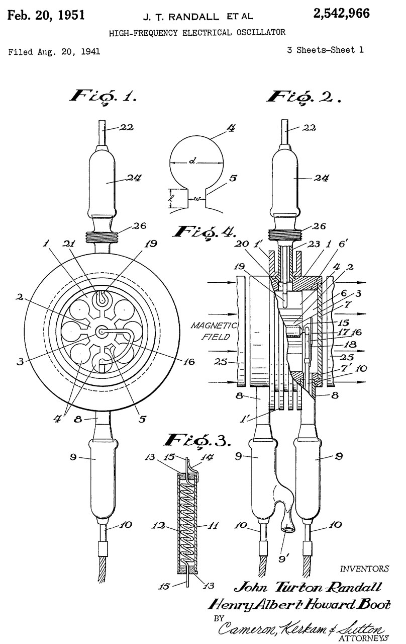
2542966 High-frequency-electrical oscillator, Howard Boot Henry Albert, Turton Randall John, English Electric Valve Co Ltd, Priority: Aug 22, 1940, Pub: Feb 20, 1951 water cooled magnetron
5 designs shown, 4 of which have power outputs of (kW):
Wavelength
(cm)
9.1
7.9
5.18
2.63
1.9
Pwr Out (kW)
150 5-10 5-10 10-15 na
Output at X-band (1.9 cm) is very low.


Charles Eisler
The Book "The Million Dollar Bend" (archive.org) brought him to my attention. He made manufacturing equipment used for making glass envelopes for radio tubes and lamps as well as other related equipment used by radio manufacturers. Instead of pulling a vacuum on the tube/lamp from the top, leaving a "tip" on the top, the vacuum is pulled out the bottom.
He holds about 55 patents.
Patents mentioned and illustrated in appendix (pg 262) and listed on page 311.
1209650 Turret attachment for machine-tools, Eisler Charles, 1916-12-19, - to allow normal lathe or drill press to have turret (chucker) lathe capabilities.
1246250 Adjustable drill-head, Eisler Charles, 1917-11-13, - Dual heads drill 2 holes at same time.
1309616 Sheet-metal device, Eisler Charles, 1919-07-15, - sheet metal nut: cap, wing, acorn
1324886 Means for Increasing the Efficiency of Swaging Machines, Eisler Charles, Westinghouse Lamp Co,1919-12-16 -
1338498 Filament-winding machine, Eisler Charles, Westinghouse Lamp Co, 1920-04-27, -
1338499 Machine for making filament-supports for incandescent lamps, Eisler Charles, Westinghouse Lamp Co, 1920-04-27, - "button press" 30,000 double buttons per day
1338500 Machine for making incandescent-lamp stems, Eisler Charles, Westinghouse Lamp Co, 1920-04-27, -
1522001 Head for constructing incandescent electric-lamp stems, Eisler Charles, 1925-01-06, -
1553309 Universal filament-coil-winding machine, Eisler Charles, 1925-09-15, -
1635316 Machine for making radio tube and lamp parts, Eisler Charles,1927-07-12, -
1637989 Machine for making glass mounts, Eisler Charles, 1927-08-02, -
1655050 Sealing-in machine for tubes and bulbs, Eisler Charles, 1928-01-03, -
1704359 Ribbon Gas Burner, Eisler Charles, 1929-03-05, - - neon signs w/quick shutoff
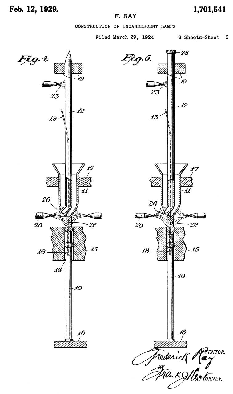
1701541 Construction of incandescent lamps, Ray Frederick, Charles Eisler, 1929-02-12, -
1828493 Disk valve for burners, Eisler Charles, Eisler Electric, 1931-10-20, -
1866634 Bead Machine, Charles Eisler,
1936426 Sealing-off and dumping mechanism for exhaust machines, Eisler Charles, Eisler Electric, 1933-11-21, -
2006544 Welding machine, Eisler Charles, Eisler Engineering Co, 1935-07-02, - Spot
2063235 Sealing machine, Eisler Charles, 1936-12-08, -
2078630 Machine for making coils of wire, Eisler Charles, 1937-04-27, -
2231617 Welding machine, Eisler Charles, 1941-02-11, - Spot
2410931 Tube cracking machine, Eisler Charles,1946-11-12, - for fluorescent lamp tubes.
2413960 Machine for sealing glass bulbs, Eisler Charles, 1947-01-07, -
2414587 Machine for piercing glass bulbs, Eisler Charles, 1947-01-21, - for 1 or 2 electrical caps
2418763 Machine for sealing and molding glass bulbs, Eisler Charles, 1947-04-08, -
2421929 Machine for sealing bulbs, Eisler Charles, 1947-06-10, -
2446000 Machine for flanging glass blanks, Eisler Charles, 1948-07-27, - Syringe tip-forming machine
2779135 Tube shrinking machine, Eisler Charles, 1957-01-29, - Syringe
2783531 Work holder turntable mechanism, Eisler Charles, 1957-03-05, - used for arc welding
Reflex Receiver
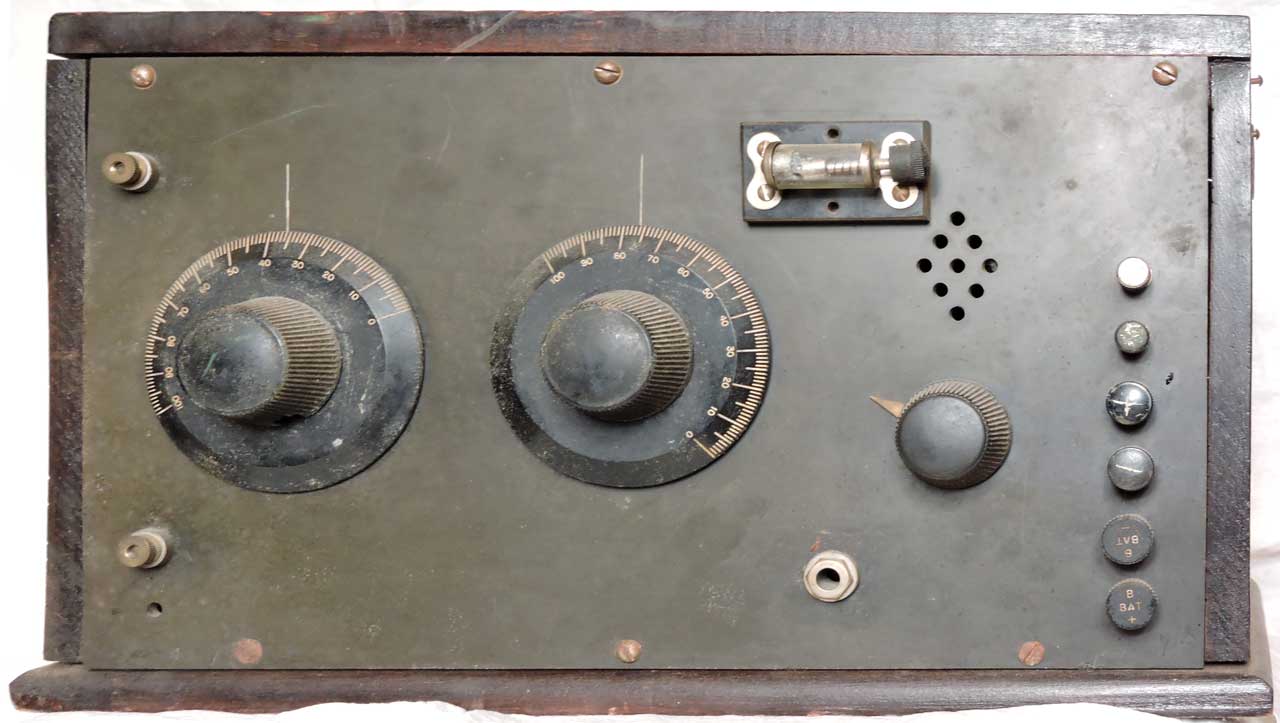
In a Reflex Receiver (Wiki) same tube is used to amplify both the radio MF signal and the audio signal. The photos and schematic were provided by Al.
Fig 1 Front Panel
Fig 2 Inside UV201 Tube
Upper Left AF trans. Upper right RF trans.
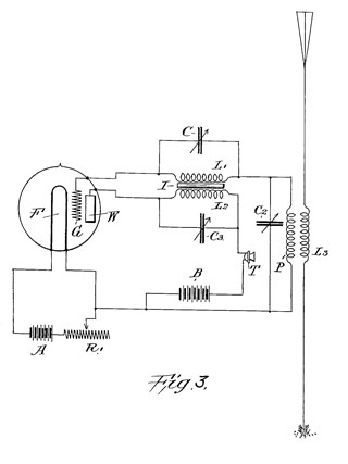
Fig 3 Schematic
Patents
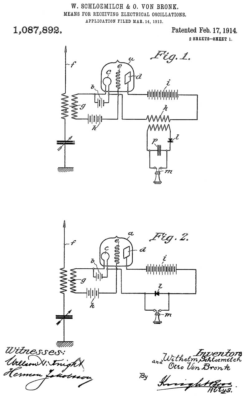
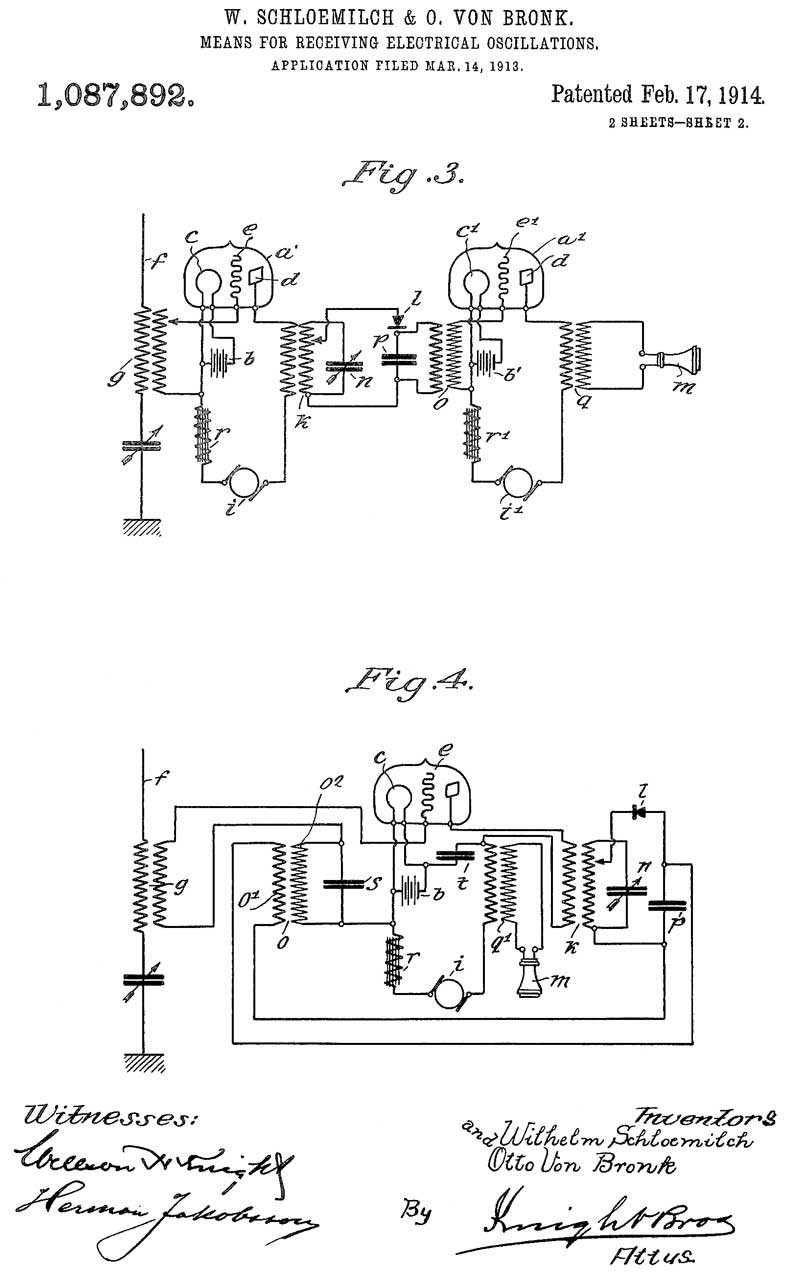
1087892 Means for receiving electrical oscillations, Wilhelm Schloemilch, Otto V Bronk, 1914-02-17, -
Fig 1, Fig 2 & Fig 3 prior art.
Fig 4 Reflex Receiver
Audio Transformer (o)
MF Transformer (k)
Note B+ Battery (i) is shown as a generator, whereas filament battery (b) is shown as a battery.
also note capacitors use units of cm rather than Farads. See Tesla.
1735185 Radio Receiver, Schaffer Walter, Telefunken AG, 1929-11-12, - still works if tube fails.
2205243 Amplifier, Robert B Dome, GE, 1940-06-18, - for use in TV IF
2777056 Reflex circuit for amplifying intermediate and detected video frequencies in same stage, Richard W Bull, 1957-01-08, - for use in TV IF stage.
2863066 Reflex circuit system, Witt David De, Sandler Harold, Roland C Wittenberg, Radio Receptor Co, 1958-12-02, - single PNP transistor

Battery Eliminators
Galvin Mfg Co got their start making these, so I was hoping to find some patents.
1682492 Radio battery eliminator, Philip E Edelman, 1928-08-28, -
1742682 Battery eliminator, Roland F Beers, Raytheon, 1930-01-07, -
1758947 Battery eliminator, Hammond Laurens, Andrews Hammond Corp, 1930-05-20, -
2208933 Battery eliminator, Loewenhaupt Emil, Telefunken AG, 1940-07-23, -
Unipotential Tubes
These tubes do not need high voltage (B+). Instead they use a voltage for the plate supply that's the same as the voltage used to heat the filament.
Learned about these (aka: Space Charge tubes) in the same YouTube video as the above battery eliminators: Fun, Fun, Fun - The History of Car Radios, 56:45 -
@ 34:59: Unipotential Tubes: 12EK6, 12BL6, 12EH5, 6CQ8, 12DL8, 12AD6, 12K5, 12AE6A, 12BK5, 12BL6, 12AF6, 12BL6, 12CA5, ...
Note that many radios can be run using a B+ voltage considerably below the specified value and still work in an acceptable manner.
SCR-57 WE Aircraft Interphone
This W.W.I Interphone system works with the SCR-59 receiver (see below).
This may have been used in the Curtiss JN Jenny biplane (Wiki).
This unit has had some restoration. It's missing some parts but is in very nice condition.
Photos
Fig 1
Fig 2
Fig 3
Fig 4
Operation
No tubes are used. Instead carbon microphones, powered by (D?) cell batteries uses transformers to feed headphones.
Works with the WE 300 series carbon mikes (See car intercom 318W mike & related patents).
The method of operation is the same as for the Acousticon Model SRD "Carbon". No tubes, a carbon mike and DC source drives an earphone.
Patents
1296687 Means for signaling from captive balloons, Harold W Nichols, Western Electric, 1919-03-11, -
This system is based on modulating an RF carrier. It is not an intercom.
1340942 Signaling system, George D Edwards, Western Electric, App: 1917-11-28, Pub: 1920-05-25, - composite telephone & telegraph
1484765 Telephone system, George D Edwards, Western Electric, App:1919-04-12, Pub: 1924-02-26, - "...phone systems and more particularly to train dispatching and similar systems having a non-loaded copper metallic open wire circuit and in which a large number of stations are bridged across a common line of considerable length."
1565628 Telephone intercommunicating system for aeroplanes, George D Edwards, William H Capen, Western Electric, App: 1920-09-25, Pub: 1925-12-15, - SCR-57
Fig 1 shows a radio receiver (RA) and a radio transmitter (TA) each connected to an audio intercom system that has three stations. Included is the 4Volt battery (E) made up of a couple of lead acid cells and a single audio transformer with the carbon mike elements switched into the primary (P) along with the battery and the receivers all on the secondary (S).
Fig 2 shows the wiring arrangement with wooden boxes with hinged lids. Note that the plugs are all solid metal, i.e. single terminals so it takes a pair of them on a block to make a 2-wire circuit.


SCR-59 1918 WE 3 Tube Aerial Radio Receiving Set
The Army Signal Corps used the BC-14 Crystal Set Receiver that had an SCR number lower by a count of five, i.e. SCR-54 (Wiki).
Some W.W. I aircraft use the:
SCR-57 Interphone that allowed the pilot to communicate with an observer or gunner. Uses six BA-3 batteries.
SCR-59 Receiver - First tube receiver used in US military aircraft.
SCR-68 Transmitter/Receiver
Photos
Fig 1
Fig 2
Fig 3 Shown prior to installing tubes.
Fig 4 Shown prior to installing tubes.
Fig 5 Schematic
Fig 6 Spare Condenser Assembly
C2 + R1, C3, C4
For C3 or C4 the parallel resistor would
need to be disconnected
Fig 7 Typical Condenser Assembly - 3 Tubes
Fig 8 Tubes installed
Fig 9 Kellog S&S Co 178-C Chest Microphone, 65A Earphone & 102 Four Prong Plug
It looks very similar to the one in the wiring diagram, except:
* The plug has the wrong pin spacing and pin diameter,
* Combined mike and ear phone, not separate mike.


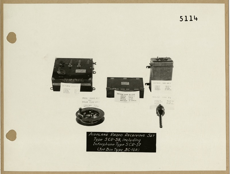
Major Components (Radionerds)
Interphone Type SCR-57 (Set Box Type BC-10A)
Reel Type RL-2 and Drum Type DR-2
A Battery: Type BB-4 (4 Volt, 2 cell, lead acid)
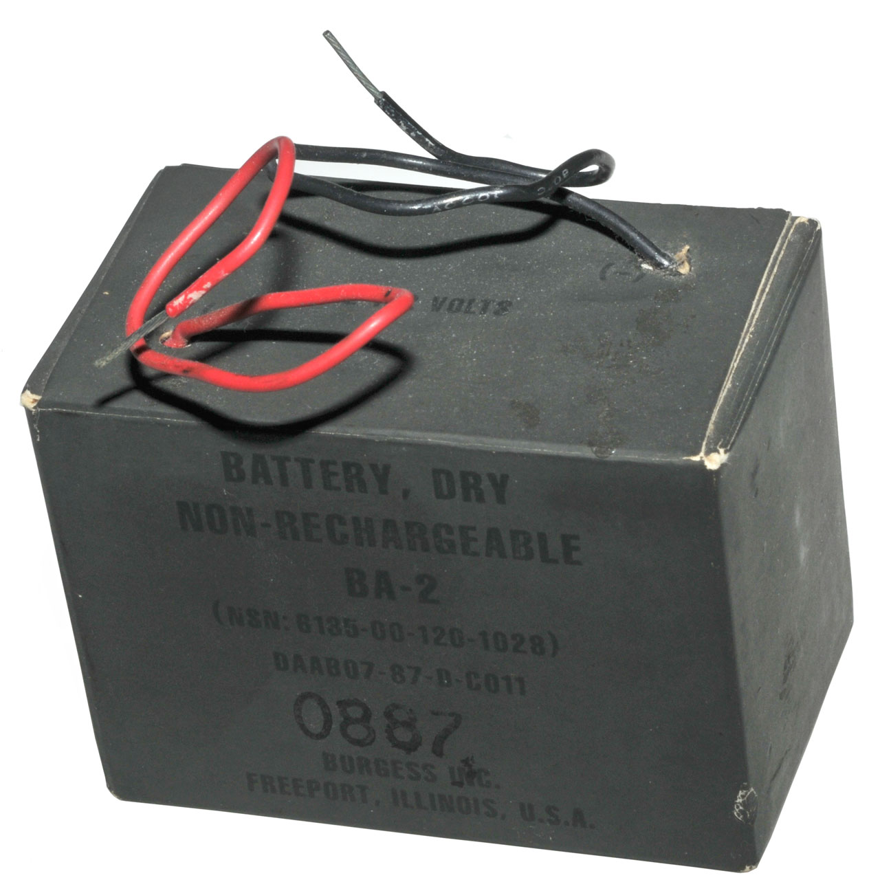
B Battery: BA-2
Telephone Transmitter (Carbon Mike) T-1 or T-3 9326 W Transmitter)
P-11 Headset
Uses Choke-Resistor-Capacitor coupling, not transformers
(the BC-13-A is a 1918 Transmitter-Receiver, Radio Museum)
BA-2 22.5 Volt B+ Battery
3 7/16 l x 2 1/32 w x 2 19/32 h

WE 396A Chest Horn Carbon Microphone
This appears to be the correct mike for the SCR-57 and SCR-59.
For another WE 300 series microphone see car intercom 318W mike & related patents
The girls at the W.W.II fighter command center that were using Chain Home radar to locate German planes used a very similar or maybe this model of chest microphone.
See: An Instantaneous Direct-reading Radiogoniometer\Ref 2.
Fig 1
Fig 2
Patents
1565581 Telephone transmitter, Moore Charles Ruby, Western Electric, 1925-12-15, -"...highly efficient and economical transmitter having a high resistance path through a comminuted (Wiki) material, whereby the transmitter may be operated directly across a voltage of a commercial telephone circuit."
1583416 Vibration-responsive apparatus, Charles R Moore, Western Electric, 1926-05-04, - dampening to get better frequency response
Fig 1. Telephone Receiver application
Fig 2. Receiver dampening device
Fig 3. Transmitter application
Fig 4. dampening device assembled with diaphragm
Fig 5. An element of dampening device
Fig 6. Vibrating reed application
1660990 Sound-responsive device, Harold F Dodge, Western Electric, 1928-02-28, - to flatten the frequency response
SCR-68
Since I have the SCR-57 interphone and SCR-59 receiver I guessed that there must be an SCR-58 transmitter, but could not find it. I did find the SCR-68 (Wiki).
Patents
John Stone Stone (Wiki) getting three dozen patents in a single block may be the most I've seen. "No man has contributed more to the advancement of the Radio Science than has John Stone Stone, and no man is more thoroughly entitled to the full and grateful appreciation of the entire Radio World." (Clark, George H. (1946). The life of John Stone Stone: Mathematician, physicist, electrical engineer and great inventor, pg 137).


714756
Method of selective electric signaling, John Stone Stone, Brainerd T Judkins, Louis E Whicher, Alexander P Browne, 1902-12-02
714831
Apparatus for selective electric signaling, John Stone Stone, Brainerd T Judkins, Louis E Whicher, Alexander P Browne,
714832 Apparatus for amplifying electromagnetic signal-waves,
714833 Apparatus for amplifying electromagnetic signal-waves,
714834 Apparatus for selective electric signaling,
RE12141 Apparatus for selective electric signaling, John Stone Stone, Stone Telegraph and Telephone Co, 1903-08-25
RE12149 Apparatus for selective electric signaling, John Stone Stone, Stone Telegraph and Telephone Co,
767970 Apparatus for simultaneously transmitting and receiving space-telegraph signals, John Stone Stone, 1904-08-16
767971 Wireless-telegraph receiving device, John Stone Stone,
767972 Method of receiving space-telegraph signals, John Stone Stone,
767973 Apparatus for increasing the effective radiation of electromagnetic waves, John Stone Stone, assigned: William W. Swan,
767974 Apparatus for increasing the effective radiation of electromagnetic waves, John Stone Stone, assigned: William W. Swan,
767975 Space telegraphy, John Stone Stone, assigned: William W. Swan,
767976 Space telegraphy, John Stone Stone, assigned: William W. Swan,
767977
Space telegraphy, John Stone Stone, assigned: William W. Swan,
767978 Space telegraphy, John Stone Stone, assigned: William W. Swan,
767979 Space telegraphy, John Stone Stone, assigned: William W. Swan,
767980 Space telegraphy, John Stone Stone, assigned: William W. Swan,
767981 Space telegraphy, John Stone Stone, assigned: William W. Swan,
767982 Space telegraphy, John Stone Stone, assigned: William W. Swan,
767983 Space telegraphy, John Stone Stone, assigned: William W. Swan,
767984
Space telegraphy, John Stone Stone, assigned: William W. Swan,
767985 Space telegraphy, John Stone Stone, assigned: William W. Swan,
767986 Space telegraphy, John Stone Stone, assigned: William W. Swan,
767987
Space telegraphy, John Stone Stone, assigned: William W. Swan,
767988
Space telegraphy, John Stone Stone, assigned: William W. Swan,
767989
Space telegraphy, John Stone Stone, assigned: William W. Swan,
767990 Space telegraphy, John Stone Stone, assigned: William W. Swan,
767991 Space telegraphy, John Stone Stone, assigned: William W. Swan,
767992 Space telegraphy, John Stone Stone, assigned: William W. Swan,
767993 Space telegraphy, John Stone Stone, assigned: William W. Swan,
767994 Space telegraphy, John Stone Stone, assigned: William W. Swan,
767995 Space telegraphy, John Stone Stone, assigned: William W. Swan,
767996 Space telegraphy, John Stone Stone, assigned: William W. Swan,
767997 Space telegraphy, John Stone Stone, assigned: William W. Swan,
767998 Space telegraphy, John Stone Stone, assigned: William W. Swan,
767999 Space telegraphy, John Stone Stone, assigned: William W. Swan,
768000 Space telegraphy, John Stone Stone, assigned: William W. Swan,
768001 Space telegraphy, John Stone Stone, assigned: William W. Swan,
768002 Space telegraphy, John Stone Stone, assigned: William W. Swan,
768003 Space telegraphy, John Stone Stone, assigned: William W. Swan,
768004 Space telegraphy, John Stone Stone, assigned: William W. Swan,
768005 Space telegraphy, John Stone Stone, assigned: William W. Swan,
818236
Space signaling system, Cornelius D Ehret,
1906-04-17
818363
Art of signaling through space, Cornelius D Ehret,
879532
Space telegraphy, Lee De Forest, DeForest Radio Telephone Co,
1908-02-18
1103688
Electric relay, Wilton Lancaster Richards, Western Electric, 1914-07-14
1129942
Gaseous repeater in circuits of low impedance, Harold De Forest Arnold, Western Electric, 1915-03-02
1129943 Gaseous repeater in circuits of low impedance, Harold De Forest Arnold, Western Electric, "
1129959
System for amplifying electric waves, Edwin H Colpitts, Western Electric, "
1130008
Audion, Alexander Mclean Nicolson, Western Electric, "
1130009 Audion, Alexander Mclean Nicolson, Western Electric, "
1130042
High-current-output audion, Hendrik Johannes Van Der Bijl, Alexander Mclean Nicolson, Western Electric, "
1130043
Alternating-current-responsive apparatus, Hendrik Johannes Van Der Bijl, Western Electric,
"
1255211
System for the successive amplification of energies, Alexander Mclean Nicolson, Western Electric, App: 1915-06-08, W.W. I, Pub: 1918-02-05, - This looks like the SCR 59 receiver circuit.
1918-02-05
1784957
Electric wave transmission system, Philander H Betts, Western Electric, App: 1924-12-13, Pub: 1930-12-16, -
Frank Conrad Patents (Spark Museum)
1456867
Apparatus for the receipt of wireless impulses, Conrad Frank, Westinghouse - tube(s) drive relay
1923-05-29,
1502848
Tuning system of antenne, Conrad Frank, Westinghouse - for undamped waves crystal or tube
1924-07-29
1528047
Wireless telephone system, Conrad Frank, Westinghouse - voice modulator (do not understand the two tuned circuits)
1925-03-03
1563342
Signaling system, Conrad Frank, Westinghouse - fed from AC mains, voice or CW transmitter
1925-12-01
1586653
Wireless transmission system, Conrad Frank, Westinghouse - square, delta or star horizontal dipoles (short length?) 1926-06-01
1640534
Wireless antenna system, Conrad Frank, Westinghouse - square, delta or star horizontal dipoles (short length?)
1927-08-30
1645291
Polyphase plate-circuit excitation system, Conrad Frank, Westinghouse - fed from AC mains
1927-10-11
1655985
Wireless receiving cabinet, Conrad Frank, Westinghouse - SCR 70 (See Spark Museum)
1928-01-10
1664192
Wireless receiving set, Conrad Frank, Westinghouse - Crystal radio using variometer (G3YNH) as variable inductance
1928-03-27
References
National Air and Space Museum -
Roaring Twenties antique Radio Museum - World War I Radios - Manuals - Related web pages -
National Museum of American History -
Airplane Radio Telephone Sets, Radio Pamphlet No. 20, Signal Corps, U.S. Army, 1919 - (RA_PA-20_2nd_Ed._May_21%2C_1919.pdf) missing SCR-59 pages
Radio Museum - SCR-59 -
VT-1 Tube
Singal Corps
VT 1
Western
Electric Co. Inc.
Pat. in U.S.A.
1-15-07 Two Patents
2-18-08, 4-27-15
12-19-16
Pat. Applied for
CW 933
Fig 1
Fig 2
Fig 3
Patents
841305 Winding-machine, George F Atwood, Western Electric, 1907-01-15, - telephone loading coils
841307 Electric annunciator, Charles C Blake, Western Electric, 1907-01-15, - electromagnet
841335 Adding-machine attachment, Frank R Mcberty, Western Electric, 1907-01-15, - motor & 4 cams w/switches
841386 Wireless telegraphy, Lee De Forest, 1907-01-15, -
841387 Deivce for Amplyfing Feeble Electrical Signals, Lee De Forest, 1907-01-15 -
841511 Apparatus for manufacturing hollow glassware, Friedrich Arthur Grosse, 1907-01-15, -
879409 Wireless telegraphy, George W Pierce, Massachusetts Wireless Equip, 1908-02-18, -
879532 Space telegraphy, Lee De Forest, Forest Radio Telephone, 1908-02-18, -
1137275 Filament for audions, Alexander Mclean Nicolson, Western Electric, 1915-04-27, -
1209324 Electron-emitting cathode and the process of manufacturing the same, Alexander Mclean Nicolson, Emerson Church Hull, Western Electric, 1916-12-19
1325865 Vacuum-tube socket, Herbert E. Shreeve, Western Electric, App: 1916-05-20, W.W.I, Pub: 1919-12-23, - VT-1 & socket
Note trapezoid shaped plates, not cylindrical plates.
1401121 Mounting for vacuum-tubes, Roy M Allen, Western Electric, 1921-12-27, - VT-1 vibration mounting for VT-1, i.e. for use in an airplane.
1464104 Selective apparatus for signaling circuits, Nicolson Alexander Mclean, Western Electric, App: 1917-07-26, W.W.I, Pub: 1923-08-07, - cylindrical anode
1480219 Vacuum tube, Nicolson Alexander Mclean, Western Electric, App: 1917-06-25, W.W. I, Pub: 1924-01-08, - Looks similar to the VT-1 - cylindrical anode
1491362 Vacuum tube, Herbert E Shreeve, Western Electric, App: 1918-02-20, Pub: 1924-04-22, - Tube elements and base look like VT-1
"... tubes, and more particularly it relates to improvements in shells for audions whereby each Audion is provided with terminal connections which may be readily made or severed without disturbing the fixed wiring of the circuits allied therewith."


Links
NBS Circular 120: article about Construction and Operation of a Simple Homemade Radio Receiving Outfit (pdf) - Circular 120 (pdf)RCA Radiola III and III-A By Doug Criner - includes info on WD-11 tube substitutions
Dialcover by Bill Turner - parts and manuals
1922 Radiola Senior -
Antique Radios Inc - Arbe-III Universal Battery Eliminator -
Pamphlet No. 20 Airplane Radio Telephone Sets (Types SCR-68, SCR-68-A, SCR-114, SCR-116, SCR-59, SCR-59-A, SCR-75, SCR-115) [No. 20 only first 31 pages)
Ground Radio Telephone Sets, Radio Communication Pamphlet No. 22, Dec 1921, War Department Doc No. 1091, 28 pages - SCR67 & SCR-67-A (SCR-67.pdf) - intercommunicates with SCR-59, SCR-68 and others. Nominal range to aircraft 2 to 3 miles, to another ground set 5 to 7 miles. Tx between 250 (1.2 MHz) to 450 meters (667 kHz), Rx between 200 (1.5 MHz) to 700 (429 kHz) (or 800 (375 kHz)) meters.
Roaring Twenties Antique Radio Museum - World War I Radios -
Radio Nerds: S.C.R. Pamphlet No. 20 SCR-68 Airplane Radio Telephone Set (SCR-68.pdf) - includes info on the SCR-57 and SCR-59
Set, Radio Telegraph Type SCR-105, Radio Communication Pamphlet No. 25, Sep 1921, 29 pgs (SCR-105/SCR-105.pdf) - Tx: 150, 180, 210, 240, 270 or 300 meters; Rx quenched spark between 100 and 550 meters. uses P-11 or HS-11 headsets, CD type cords,
Undamped Wave Radio Telegraph Types SCR-127 and SCR-130, Radio Communication Pamphlet No. 26 (2nd ed), Jan 1921, 40 pgs (SCR-127AndSCR-130/SCR-127AndSCR-130.pdf) - Tx; 550 to 1100 meters, Rx 350 to 1100 meters.P-11 headphones on pdf page 24;
Radio Communication Pamphlet No. 27: Sets, Radio and Telegraph, types SCR-109-A and SCR-159, June 1922, 41 pgs, (SCR-109-AAndSCR-159.pdf) - Tx: 300 to 500 meters, Rx 300 to 1100 meters. Three modes: Undamped wave (CW) 60 miles; Buzzer modulated telegraphy 50 miles, Telephony 30 miles. P-11 headset & CD cords,
Airplane Radio Sets, Types SCR-133, 134, 135 and Interphone Sets SCR-155, 160 and Receiving Equipment used in Conjunction therewith, Radio Communication Pamphlet No. 42, March 1925 (US_War_Department_Airplane_Radio_Sets_Types_SCR-133_134_135_1925_text.pdf) - uses same cords as SCR-59.
American Vacuum Society: Vacuum Science & Technology Timeline -
1915: WE begins production of biased tubes for AT&T starting with Type M/101A;Lamps & Tubes: Western Electric SIGNAL CORPS VT-1 Triode - great photographs
1917: WE develops VT-1 and VT-2 for Signal Corps Goes into high production;
1920: RCA Radiotron UV-200, UV-201
1922: RCA Radiotron WD-11
Back to Brooke's PRC68, Products for Sale, Telephones, U229 Audio Accesories, Audio Connectors, Military Information, Electronics, Personal Home page
page created 31 Dec 2011.