Telegraph Equipment
© Brooke Clarke 2006 - 2022
Background
Morse Patent
Telephone
Ticker Tape
Western Union 5A Black Box stock
quotation printer
Teletype model 36 Monopulse Printer
Teletype
Overview of
Teleprinter Model Numbers
Table of 5
Level Teletype Code
Punched Paper
Tape - 5, 6, 7, & 8 level
Telegraphic Fire-Alarm
Protocol
Keys
Relays
Pole Changer
255A Polar Relay
17-B Polar Relay
Track Relay
Dial Telegraph
Sounders
Veeder Counter
Veeder Speed Indicator
Connectors
Binding Post
Tip
Banana Plug
1/4" Phone Plug
Fahnestock
Clip
Electromagnets
Patents
Telegraph Paper Tape &
Jacquard Loom
Boehme
Gill Selective Telegraph
Gamewell (new
web page)
Video
Links
Background
In 1832 Joseph Henry published an
article describing how he made electro-magnets that could support
hundreds (maybe thousands) of pounds by wrapping Bell Wire with
fabric to insulate the wire from adjacent turns and using many
turns on a soft iron core. At this time Bell Wire was a
flexible metal wire without any insulation that was used to
connect a pull cord with a small bell, like in a hotel or
mansion. Prior to this there had been a publication showing
the uninsulated wires could be wrapped so the did not touch each
other or the soft iron and that would magnify the magnetic effect.
Iron wire was commonly used to make "Cards" that were used to
remove stuff from Sheep's wool prior to spinning. If you
know about the beginning of Copper wire please
let me know.
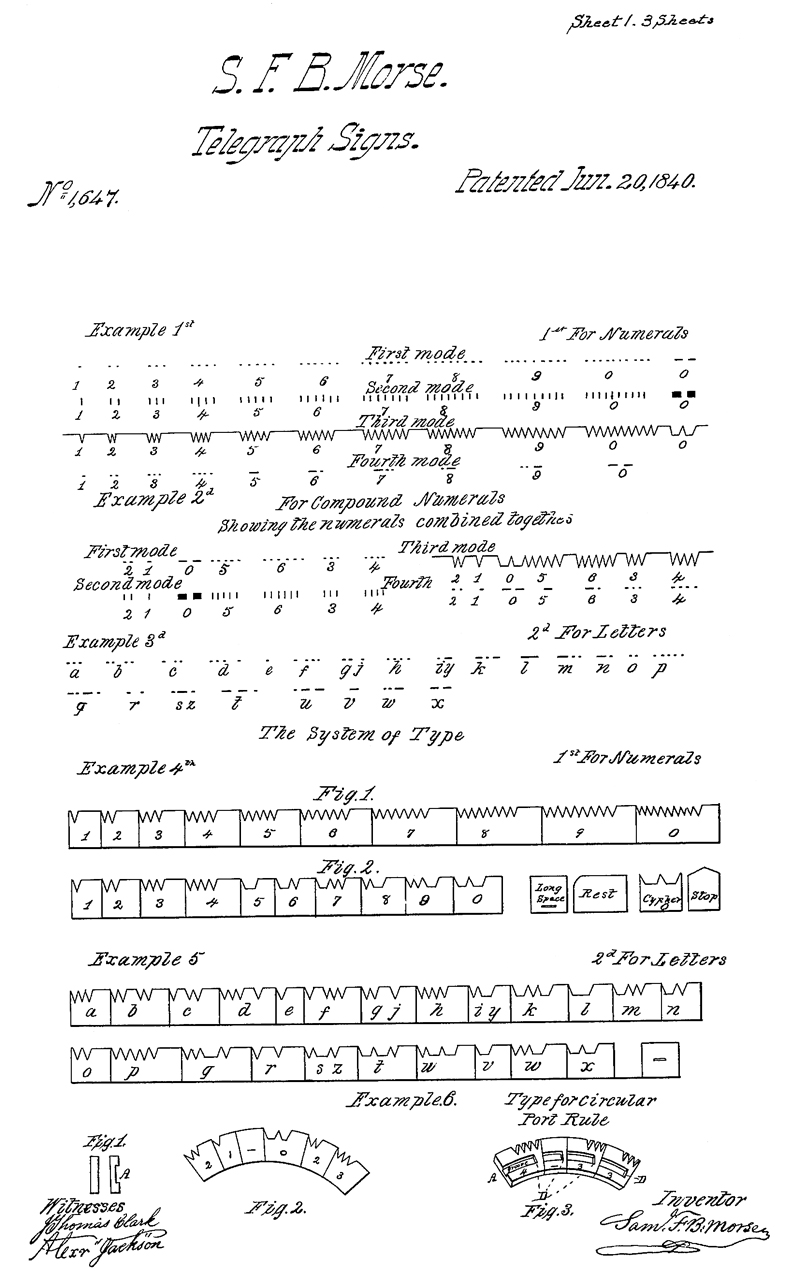
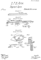
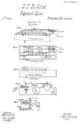
Morse Patent
1647
Telegraph Signs, S.F.B. Morse, 1840-06-20, -
|

|
 |
 |
RE79
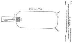
Mode of Communicting Information by Signals by the
Application of Electromagnetism, S.F.B.
Morse, 1846-01-15, -
Pages 1, 2 & 3 are the same as 1647.
Diagram No. 11 shows loop with sender, batteries and an
acoustic sounder.
|
|
|
|
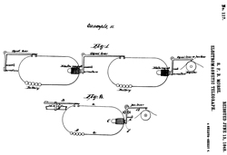
RE117
Electromagnetic Telegraph, S.F.B. Morse, 1848-06-13, -
The first few figures are the same.
|
|
|
|
Starting about 1840 the telegraph that uses current through a wire
to activate an electromagnet started. By 1865 there was over
83,000 miles of telegraph wire being used in the U.S.
Even though the telephone came into service there were still
telegraph offices and rail road telegraph systems in use up into
the 1950s.
The early telegraph systems were powered by
wet cell batteries. Later some
were powered by the Edison DC utility.
Although the very early telegraph equipment tried to allow for a
non skilled operator (Morse's patent was for a machine that
printed a strip of paper with dots and dashes), the method that
won out was based on an operator trained to recognize the sound of
the Morse characters on a "Sounder". This was much faster
than other methods.
But later the Hughes Printing Telegraph was used on high volume
lines to increase throughput. This machine has a keyboard
that came from a piano.
Spark Museum:
Early Telegraph
Apparatus -
Also see
Stock
Ticker Patents.
Telephone
In 1873 there were more than 150,000 miles of telegraph lines in
the U.S. alone operated by Western Union who had bought up most of
the smaller companies.
When A. G. Bell
invented the telephone
he used a coil that was very similar if not exactly the same as
those used for telegraph sounders.
A. G. Bell
patent # 174465 Telegraphy,
March 7, 1876 379/167.01; 178/48 - Note the patent
title is Telegraphy because although it covers sending voice over
a wire it's main intention was to allow for multiple telegraph
circuits on one wire by using different audio frequencies.
Multiplex is the term for doing this. T.A. Edison invented
one of the ways to do this.
Protocol
A simple telegraph system using
Morse code operates by making and breaking the circuit. With
the circuit open the sounder spring holds the arm up. When
the circuit is closed current flows energizing the electromagnet
in the sounder and the arm is smartly pulled down making the click
sound. When ham operators are working CW mode the
transmitter is turned on for a tone and off for a space. The
problem with this Make-Break system is that during the break
(space) time no signal is being transmitted. That degrades
the signal to noise ratio compared to a system where there is
always something being transmitted.
When RTTY (Teletype) is being transmitted it's typically done
using frequency shift modulation. That way the transmitter
is always on and a good receiving modem can provide 100% copy with
either signal (it automatically combines both signals).
There was a problem when early Tickers were being installed where
the transmission lines were long. When on mark the tickers
would work correctly, but on space, like when the operator was not
doing anything, all the interference from adjacent telegraph lines
would cause the type wheel to move a tick or two getting out of
unison. One fix for this was to add a resistance across the
transmitter so that when in the break (space, open) condition a
small current was being pulled. But a better solution would
be to use a protocol where the polarity was reversed and at no
time was the circuit opened. I think this is the way later
model tickers operate.
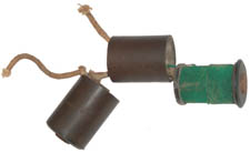
Ticker Tape
Stock ticker machines work on the step-by-step principle that's
very similar to today's "atomic" clocks. There's a solenoid
that pulls on a ratchet wheel advancing the type wheel (second
hand) one position at a time. By using either a positive
connection to the battery or a negative connection it's possible
to either step the type wheel or print a character. The
problem that plagued this system for a few decades was how to keep
all the type wheels in unison. There's a patent class just
for Unison Devices.

The letter
type wheel is above the figures type wheel and the separation
makes it easier to read the tape. By splitting the
characters onto two wheels cuts the time per character in half,
since a single shift operation is required rather than turning a
single type wheel to the next character. Stock prices used
to be reported in 1/8 of a dollar increments. There have
been different ways to get the fractions printed.
The type wheel is advanced one position by sending one pulse on
the telegraph line. So there's a ticking noise while the
wheel is turning then a louder noise when the character is
printed. This was so noisy that the machine was enclosed
under a glass dome. The dome is to cut down the noise, not
for show.
The effort to come up with a telegraph system that would not
require a skilled operator led to the stock
Ticker
Tape machine (last model intro in the 1960s) which lead to
the
teletype
machine, the first form of digital communications both first
patented in 1869. Bunnell made paper tape winders used for
Morse pen recorders, fire alarm pull box recorders (Gamewell) and
ticker tape. IEEE
history
of the Ticker Tape machine.
THE QUICK BROWN FOX
JUMPS OVER A LAZY DOG
The above is in Teleprinter font and is the shortest (33 letters)
version of this pangram. See:
http://en.wikipedia.org/wiki/List_of_pangrams#Longer_pangrams_in_English_.28in_order_of_fewest_letters_used.29
The machines were made in volume by Edison, Western Union, Burry,
New York Quotation, Commercial Telegram, Gold & Stock, Western
Union in the early 1960s ordered that all existing Ticker Tape
machines be destroyed, so today they are scarce. There
probably were over 20,000 of them at the time.
Once a day for about an hour test messages came out of New York
from Western Union. These would include the THE QUICK BROWN
FOX JUMPS OVER THE LAZY GREEN DOG, the alphabet in order, the
shifted characters in order, etc. The machines ran on
typical teletype loops of about 100 volts.
Ticker Tape machines were replaced by computers using modems, and
now the internet. When that happened they were still used
for ball games and gambling.
A system of letting everyone know stock prices at exactly the same
time is fair. If conventional teletraph is used then the
operators at either the sending or receiving end of the line may
leak sensitive information.
By 1919 Western Union had bought up hundreds of telegraph related
companies. They then supported the following ticker
machines:
- Universal
- Scott One-Wire Ticker
- Scott Two-Wire Ticker - weight driven
- Phelps Ticker
- Burry Ticker - for stock news in brokers office
- Burry Page Ticker (Scientific American, March 23, 1901
article)
- Self-Winding Ticker
When searching some key phrases are:
stock ticker
ticker tape
Ticker Tape Patents - 18
Mar 200 7 - 414 patents (about 240 MB) all realted to tickers
or something very close. Still many questions to be
andwered. Have T.A. Edison's papers on order.
UK 14403 1901 - 18 Feb 2007 have ask how to get a copy.
Appears on machine at
Early
Tech. Another
350600739
,
2135618081,
1855419371,
A guess at the Letters and Figures type wheels (based on Fig 4 in
126532):
A
|
B
|
C
|
D
|
E
|
F
|
G
|
H
|
I
|
J
|
K
|
L
|
M
|
N
|
O
|
P
|
Q
|
R
|
S
|
T
|
U
|
V
|
W
|
X
|
Y
|
Z
|
|
|
|
1
|
2
|
3
|
4
|
5
|
6
|
7
|
8
|
9
|
0
|
1/8
|
1/4
|
3/8
|
1/2
|
5/8
|
3/4
|
7/8
|
|
|
|
|
|
|
Gold & Stock high speed ticker
1934 Black Box ticker
Edison,
his life and inventions -
Stock
Ticker
Universal -
243,
332,
1292,
2030,
2101,
2106,
2187,
2313,
2351,
2391,
2408,
2712,
5777
NY Quotation Ticker
Berner Machine Labs -
Makes non working metal life size model
Claus
Studios - makes a hand painted plastic non working model
& has some real items
Teletype
The ticker type printers use a
pulse to advance the print wheel one character. If
you have just printed "B" and now want to print "A" you need to
pulse the wheel N-1 times (N is number of characters on the
wheel) which may be 26 + 10 + 10, i.e. a lot of stuff
transmitted for only one character. The teletype uses
what's called a permutation (a key word appearing in patents)
code where the number of bits for every character is the same
and a binary sequence is used. The first Baudot French
patent was for a piano type keyboard with 5 keys.
When the teletype machine is in idle (stop, marking, make)
position line current holds the selector in a fixed
position. When a key is pressed the line is opened (break,
space, start) the selector is released and is turned by a local
electric motor. This start-stop method shows up in patent
1286351 by Krum. at the end of one rotation the selector
stops leaving the line in the idle state. Computers call
this asynchronous operation since the start time of each
character depends on when the operator presses the key
(random). In the data stream prior to a letter the line
has current so the start bit is the one that opens the circuit
releasing the selector. The start bit is followed by data
bits, at first 5 an later 8 data bits, then in order to always
leave the line with current the stop bit ends in the line closed
state. Because of the inertia of the machines in order to
be sure the selector stopped 1 1/2 or 2 stop bits were used at
the end of each character. This same Start-Stop system is
used today in the RS-232 and other asynchronous data schemes.
This system has a couple of big advantages over the step-by-step
system. First it is much faster to have all the characters
much shorter on average than the step-by-step system. For
example the number of bits needed for the step-by-step system is
on average 1/2 the number of characters on the type wheel, which
would be around 30, so 15 bits per character. The 5-level
Start-Stop would have 7 bits per character so the throughput is
already more than twice as high. Also since the system
synchronizes at the start of each character there are no Unison
problems.
The other thing about Start-Stop is that you can design the
assignment of bits to each character in such a way that it's
easy to decode then mechanically. The Step-by-Step sending
machines needed to use either a circular keyboard or a piano
type keyboard because of the rotation of the commentator and the
alphabetical order of the letters on the type wheel.
Overview of Teleprinter Model Numbers
Numbered models are pretty much a Bell System thing. Some
model numbers were assigned to machines that were never
produced. The comments are not mine but belong to Walt.
Model 10 - Western Electric machine, by Pfannenstiehl et
al Typebar page printer with stationary platen
Model 11 - Morkrum, typewheel tape printer Model 12 - well-known
machine, Morkrum, typebar page printer with moving platen
Model 13 - Model 10 retrofitted with Morkrum Model 12 typing
unit
Model 14 - well-known Morkrum machine It seems, according
to the catalog, that the GPE perforator and XD
transmitter-distributor were also considered part of the Model
14 line. (Western Union called it the 2-B)
Model 15 - well-known Teletype machine
Model 16 - a stock ticker that was not produced because of the
1929 depression. Design was by Walt's group. It had
dual type baskets, one for letters and one for figures.
Black box stock ticker - did not have a model number.
(called
5-A by Western Union)
Model 17 - Designed by Kleinschmidt, a Hellschreiber-like
machine. Don't know if it could interoperate with a real
Hellschreiber.
Model 18 - Kleinschmidt designed page printer for Western
Union. Not manufactured. It had a lot of parts in
common with the 21-A multiplex tape printer, but was a simplex
(i.e. start-stop) machine. (Since then I've found a parts
manual for Model 18, so maybe it was manufactured.)
Model 19 - well known Teletype machine There is also the
DPE perforator, being a perforator-only version of the Model 19
keyboard.
Model 20 - fairly well known machine, up/low 6-level version of
Model 15 used for Teletypesetter
Model 21 - The Western Union 21-A multiplex tape printer
that has a few parts in common with Model 14 (Peculiar case
where the Western Union model number seems to be the Teletype
model number too.)
Models 22, 23, 25 and 27 - Walt doesn't remember anything about
them. Probably machines that were designed but not manufactured.
Model 24 seems to be an early version of Model 26, lacking some
features of the latter. Which means the typewheel
positioning mechanism is based on the stock ticker.
Model 26 - fairly well known machine. Was intended to be a
low-cost machine for TWX service. It turned out that by
concentrating on one model, the Model 15, they could achieve the
cost-reduction goal more easily.
Model 27 - referenced in museum book - says that is the model
number for TT-4/TG (XC-2) a proposed military machine with a
typing unit like a Model 26 and a keyboard like a Model
31. Says only 10 units were made. Note that the
production TT-4/TG is a Kleinschmidt machine.
Model 28 - well known machine. 10,000 of them were ordered
by the Navy before it went into production. Sales wanted
to give it a new name or model number to indicate it was a
complete break with the past; but Bell Labs insisted that model
numbers continue in sequence.
Model 29 - One tradition says this was to be a 28-line
replacement for the Model 20, and didn't sell. Then there
was the Model 28 IDP ASR
set which a lot of us called the Model 29, rightly
or wrongly. But this is not inconsistent, since the IDP
set used 6-level BCD computer code and the Model 20 replacement
used 6-level TTS code.
Model 30 - Walt doesn't remember. There was a lightweight
page printer project for the military that was also an ancestor
of the 32/33 line. The military project went nowhere
because they chose the Kleinschmidt design, wanting to have a
design they could own. maybe the Navy Teletype
TT-242 that lost out to MITE...
Model 31 - fairly well-known machine. Lightweight portable
tape printer. Used a type sector printing mechanism similar to
SIGABA.
Model 32 - well known - 5 level low cost light duty
Model 33 - well known - 8 level
low cost light duty Initially there was no interest
from either the Bell System or Western Union in light-duty
machines. Teletype pushed ahead with development.
The Canadians brought in European Telex, and W.U. saw this as an
opportunity to connect with European Telex and compete with TWX,
so they very suddenly got interested in the Model 32. A
Model 28 had a life of 10-12 years in 24/7 service, which meant
that in typical TWX service it had a life of over 50 years.
Model 34 - a Model 28 in Model
35's clothing Model 35 - well known - 8-level version of Model
28
Model 35 - an Model 28 in Model 35's clothing Model 35 - 5
level version
Model 36 - Monopulse system, circa 1948. Don't know why
the model number jumped way up at that early date.
Model 37 - fairly well known. Aggregate motion printer
produced in stock ticker and page printer versions.
Model 38 - fairly well known. Up/low version of Model 33.
Model 39 - Walt doesn't know. Was after he retired.
Model 40 - well known
Model 41 - Walt doesn't know. Was after he retired.
Model 42 - Was this reserved for a 5-level version of Model
43. has been confirmed by Wayne
Model 43 - well known dot matrix page printer.
Models 44xx which were cost reduced and simplified Model 40s
Models 45xx which were enhanced Model 40s with newer electronics
Also - Teletype would make single copies of machines, or dummy
machines,
to demonstrate concepts. Walt mentioned that
in particular they would
do this at the request of young Navy
officers. Old Navy officers already
had their careers made, but younger ones were
trying to make names for
themselves and Teletype was happy to help them.
16 Mar 2007 - Following is a small sample of patents, I've found
over 300 so far relating to Step-by-Step equipment, mostly for
stock tickers.
151209 Automatic Telegraphy and Printer Therefor, T.A.
Edison, May 26, 1874, 234/106 ; 178/17R
638591
Actuating Mechanism for Key Operated Machines, D. Murray, Dec 5,
1899, 400/75 ; 234/70; 400/415; 400/478
65393
Page Printing Telegraph, D. Murray, 4 July 17, 1900, 178/25 ;
178/4; 178/92; 199/18; 234/82
685427
Automatic Actuating Mechanism for Key Operated Machines Oct 29,
1901, 400/75 ; 400/376; 400/415; 400/478
698845
Actuating Mechanism for Key Operated Machines, D. Murray, April
29, 1902, 400/75 ; 400/478
710163
Keyboard
Perforator,
D.
Murray,
Sep
30, 1902, 234/105
888335
Printing Telegraph, K.L. Krum, May 19, 1908, 178/27
862402
Printing Telegraph, K.L. Krum, Aug 6, 1907, 178/27 ; 178/40
929602
Transmitter for Electric Telegraphs and the Like, C.L. Krum, July
27, 1909, 178/79 ; 340/815.89
929603
Transmitter for Automatic Telegrapher, C.L. Krum, July 27, 1909,
178/33R
1137146
Printing Telegraph Apparatus, C.L. Krum, April 27, 1915, 178/27
1286351
Electric
Selective
System,
H.L.
Krum,
December 3, 1918, 178/33R ; 246/3; 246/5; 340/825.59 - Start-Stop
method
1232045
Selective Telegraph System and Apparatus, C.L. & H.L. Krum,
July 3, 1917, 178/27 ; 400/155.1; 400/157.2; 400/320.1; 400/470
first use of start-stop patent
1326456
Telegraph Transmitter, C.L. & H.L. Krum, Dec 30, 1919, 178/17A
; 234/89- paper tape
1360231
Printing Telegraph, C.L. & H.L. Krum, November 23, 1920, 178/4
; 178/23R; 178/33R- paper tape
1366812
Selective or Printing Telegraph, January 25, 1921, 178/17B ;
178/17R; 226/37; 400/73- paper tape
1635486
Printing or Selecting Telegraphs, C.L. Krum, July 12, 1927, 178/27
; 178/17.5- keyboard start-stop
1665594
Telegraph Printer, H.L. Krum, April 10, 1928, 178/27 - No. 12 Tape
type Printer
1745633
Telegraph Receiver, S. Morton (salt), Feb 4, 1930, 178/27 - No 14
Typebar Tape Printer
1904164
Signaling System and Apparatus, S. Morton , April 18, 1933, 178/4
; 178/23R; 178/27; 178/33R; 220/2.3R
- No. 15 Page Printer
1374606
Printing Telegraphy, H. Pfannenstiehl, April 12, 1921, 178/27 ;
400/184; 400/70- 10-A teletypewriter
1426768
Printing Telegraph Receiver, H. Pfannenstiehl, August 22, 1922,
178/27 ; 178/69.6; 400/140; 400/184; 400/185; 400/253; 400/372;
400/72
1623809
Printing Telegraphs, H. Pfannenstiehl, April 5, 1927, 178/27 ;
199/18; 400/70
1661012
Automatic Impulse Transmitter, H. Pfannenstiehl, February 28,
1928, 178/17A
1151216
Selective Electrical Signaling Apparatus, L.M. Potts, Aug 24,
1915, 178/33R - reed type start-stop selector
1229202
Telegraphic Receiver, L.M. Potts, June 5, 1917, 178/27 ; 101/110;
178/29; 370/305; 400/154.1; 400/471- 8 level code
1370669
Machine Telegram, L.M. Potts, March 8, 1921, 178/27 ; 101/93.36;
178/2F; 178/34; 178/4.1R; 178/69.6; 234/37
start-stop purmutation code
1517381
System of Telegraph Distribution, L.M. Potts, Dec 2, 1924, 178/17E
; 178/17R; 370/304 - trunk mux, Western Union Telegram
1570923
Printing Telegraphy, L.M. Potts, Jan 26, 1926, 178/27 ; 400/154.4;
400/155
- gum backed paper strip, Western Union Telegram
2181708 Printing Telegraph Apparatus, A,H, Reiber, Nov 28,
1939, 178/35 ; 178/33MP; 370/305; 400/155.1; 400/157.2
Computer Code Development Patents
The Teletype machine 5 and 8 level paper tape codes evolved into
today's 8-bit ASCII code. Note that keyboards, printers,
tape and card punches all used a more or less common code.
1274484
Tabulating Machine and Cards Therfore, R.N. Williams, Aug 6, 1918,
101/96 ; 235/432
1880408
Alphabetical Code Punching Device, J.W. Bryce, Oct 4, 1932, 234/96
; 234/103
1902060
Printing Mechanism, P. Dechene Mar 21, 1933, 101/93.25 ;
101/110; 101/93.44; 235/432
1867025
Combinatorial Hole Punch, J.R. Peirce, July 12, 1932, 234/37 ;
234/102; 234/119; 234/129; 234/18; 235/434; 235/59T
1926892
Printing Mechanism, J.W. Bryce, Sep 12, 1933, 101/96
1896555
Rotary Printing Machine, J.R. Peirce, Feb 7, 1933, 101/93.26
1981990
Printing Mechanism, F.M. Carroll, Nov 27, 1934, 101/93.46
2010652
Printing Mechanism, G. Tauschek, Aug 6, 1935, 400/141 ;
101/109; 101/399; 101/93.45; 101/93.46; 178/4; 235/432; 400/157.2;
400/161.4; 400/174; 400/62
2016682
Printing Mechanism, A.W. Mills, Oct 8, 1935, 101/93.46
89887
Printing Telegraph, G.M. Phelps, May 11, 1869 178/38 ; 178/41
RE004152 Printing Telegraph, G.M. Phelps,Oct 11, 1870,
178/41
143702 Improvement in Printing-Telegraphs, Landy T Lindsey,
May 3, 1873, 178/41 - this is the now classic teletype machine
that uses a start and stop bit to sync the receiving machine at
every character.
2384194 (Five Level) Tape Distribution System, L.M. Potts
(Teletype), Sep 4, 1945, 178/17B ; 178/42; 226/115; 242/532.6;
242/534.2; 83/70
Table of 5 Level Teletype Code
0= space (line open), 1=Mark (line has current)
Prior to the start of a character there's current in the line
(mark) holding the selector electromagnet. Each of the 32
characters always starts with a space condition (line opened to
release the selector) and the end is always a mark (current in
line to hold the selector still). This is not shown in the
table, just the 5 character elements. The code elements are
sent left to right. For example to send A:
The line has current (mark),
the start bit (space) is sent for 1 time unit,
a mark is sent for 1 time unit,
a mark is sent for 1 tine unit,
a space is sent for 1 time unit,
a space is sent for 1 time unit,
a space is sent for 1 time unit,
the line is put in mark for at least 1-1/2 time units (maybe 2
time units)
All letters are CAPITAL, there are no lowercase letters in the 5
level code.
Arranged
Alphabetically
|
Arranged
by Code
|
Letters
|
Figures
|
Code
binary
|
Code
decimal
|
A
|
-
|
11000
|
24
|
B
|
?
|
10011
|
19
|
C
|
:
|
01110
|
14
|
D
|
$
|
10010
|
18
|
E
|
3
|
10000
|
16
|
F
|
!
|
10110
|
22
|
G
|
&
|
01011
|
11
|
H
|
<pound
Sterling>
|
00101
|
05
|
I
|
8
|
01100
|
12
|
J
|
'
|
11010
|
26
|
K
|
(
|
11110
|
30
|
L
|
)
|
01001
|
09
|
M
|
.
|
00111
|
07
|
N
|
,
|
00110
|
06
|
O
|
9
|
00011
|
03
|
P
|
0
|
01101
|
13
|
Q
|
1
|
11101
|
29
|
R
|
4
|
01010
|
10
|
S
|
Bell
|
10100
|
20
|
T
|
5
|
00001
|
01
|
U
|
7
|
11100
|
28
|
V
|
;
|
01111
|
15
|
W
|
2
|
11001
|
25
|
X
|
/
|
10111
|
23
|
Y
|
6
|
10101
|
21
|
Z
|
"
|
10001
|
17
|
Carriage Return
|
00010
|
02
|
Line Feed
|
01000
|
08
|
Letters
|
11111
|
31
|
Figures
|
11011
|
27
|
Space
|
00100
|
04
|
Blank
|
00000
|
00
|
|
Code
decimal
|
Code
binary
|
Letters
|
Figures
|
00
|
00000
|
Blank |
01
|
00001 |
T
|
5
|
02
|
00010
|
Carriage Return |
03
|
00011
|
O
|
9
|
04
|
00100
|
Space |
05
|
00101
|
H
|
<pound
Sterling> |
06
|
00110
|
N
|
,
|
07
|
00111
|
M
|
.
|
08
|
01000
|
Line Feed |
09
|
01001
|
L
|
)
|
10
|
01010 |
R
|
4
|
11
|
01011 |
G
|
&
|
12
|
01100 |
I
|
8
|
13
|
01101
|
P
|
0
|
14
|
01110 |
C
|
:
|
15
|
01111 |
V
|
;
|
16
|
10000 |
E
|
3
|
17
|
10001 |
Z
|
"
|
18
|
10010 |
D
|
$
|
19
|
10011 |
B
|
?
|
20
|
10100 |
S
|
Bell
|
21
|
10101 |
Y
|
6
|
22
|
10110 |
F
|
!
|
23
|
10111 |
X
|
/
|
24
|
11000 |
A
|
$
|
25
|
11001 |
W
|
2
|
26
|
11010 |
J
|
'
|
27
|
11011 |
Figures |
28
|
11100 |
U
|
7
|
29
|
11101 |
Q
|
1
|
30
|
11110 |
K
|
(
|
31
|
11111 |
Letters |
|
Punched Paper Tape

|
The 3 data holes between the sprocket holes
and the edge of the tape are the same for 5, 6, 7 & 8
level tapes.
The holes on the other side of the sprocket (marked "B" in
the drawing) change in number, either 2, 3, 4 or 5 holes.
On the Model 33ASR Teletype the
plastic cover that holds down the paper tape has a "V"
shape so when you pull up the paper the tail of the
punched tape has a "V" notch at the end. The paper
still in the machine has a point at the beginning like an
arrow. So you know which end is which.
I used an electric eraser with a custom built accessory
that was a metal rod with a disk at the end. The
disk had a couple of 1" high pins sticking up. This
would allow winding up a long paper tape very
quickly. If done correctly the pointed end would be
on the outside.
|
National Archives Catalog: Selected scenes
from "Large Communication Center", Pentagon Building,
Washington, DC, Video and text page description
Telegraphic Fire-Alarm Recorder
These recorders write on the paper tape the number of the box
making the call. They need to be very reliable and
maintenance free. Many have glass panels to allow viewing
the inside without opening the box up which may cause problems
(probably like something getting inside that shouldn't be
there). The most common name was Gamewell.
Note that when one of these recorders is connected to a dial
telephone line in a certain way when the phone dials the recorder
is started and records the dial pulses on the paper tape.
One of these machines could be left for a long time with no
maintenance. Maybe once a week or month someone would come
by and tear off the printed tape. There is no time stamping
or any indication of when a call was made, just the number dialed.
Dr. William F. Channing & Moses G. Farmer Boston, 1852.
Class 178 is Telegraphy oldest 1837 about 13,400 patents
Class 340 is Communictions Electrical oldest 1840, about 88,888
patents
120395
Improved Fire Alarm and Police Signal Box, W.J. Philips, Oct 31,
1871, 340/288 ; 178/2R
127844
Improvement in District and Fire Alarm Telegraphs, E.A. Calahan,
Jun 11, 1872, 340/295
146603
Improvement in Electric Bell Striking Apparatus, L.H. McCullough,
Jan 20, 1874, 340/398.1 - alarm bell
146698
Fire-Alarm Telegraphs, L.H. McCullough, Jan 20, 1874, 340/295 -
Once a box starts to send an alarm, all boxes further from the
station are cut off to prevent multiple alarms.
146812
Telegraph Signal Boxes, T.A. Edison, Jan 27, 1874, 340/295 -
referrences E.A. Calahan 127844 prior art
147186
Improvement in Morse-Telegraph Registers, John E. Smith, Feb 3,
1874, 178/95 ; 178/92 - auto starting, only dots & spaces for
fire reporting
148215
Telegraphic and Thermostatic Fire Alarms, A.F. Johnson, Mar 3,
1874, 340/535 ; 340/542
148833
Fire-Alarm Telegraphs, J.F. Kirby, Mar 24, 1874, 340/304
149677
Improvement in Electro-Magnetic Alarms, F.L. Pope, Apr 14,
1874, 340/392.1 - feedback to keep it ringing
150513
Telegraphic Fire-Alarm Boxes, J. Beamer, May 5, 1874, 340/307 ;
178/83
153498
Electric Signaling Apparatus, W.H. Sawyer, July 28, 1874, 340/294
- repeats house # to indicate the type of help needed
153958
Fire-Alarm Telegraphs, A. Halbrook, Aug 11, 1874, 340/815.58 ;
976/DIG.65; 976/DIG.68; 976/DIG.69 - time delay as signal
155207
District Alarm-Telegraph, W.D. Snow, Sep 22, 1874, 340/535 ;
178/86; 200/33R; 340/292; 340/592
155208
Electrical Thermostatic Alarms, W.D. Snow, Sep 22, 1874, 340/592 ;
340/393.2; 374/141; 374/201
156114
Fire Alarm Registers, J.O. Alley, Oct 20, 1874, 340/815.69 ;
377/92
157002
Electric
Fire-Alarm
Signal-Boxes,
Z.P.
Hotchkiss,
Nov 17, 1874, 340/301 ; 70/339; 70/454
158715
Telegraph
Signal
Apparatus
(Hotel),
J.W.
Kates, Jan 12, 1875, 340/293 ; 178/17R
169087
Fire-Alarm Telegraph, Oct 26, 1875, 340/291 ; 178/3; 178/73;
340/295
1779664 Code Register, L. Degen, October 28, 1930, 346/93 ;
178/42; 346/105
380779
- Message Recording Aparatus, F.A. Skelton,Octr 26, 1909, 346/77R
; 178/92; 346/146; 346/78 - police system, ink pen type
938285
Electric
Signal
Recorder,
N.H.
Suren,
Oct 26, 1909, 346/50 ; 178/92; 346/136; 346/141; 346/77R; 83/70 -
Gamewell
938286
Electric Signal Recorder, N.H. Suren, Oct 26, 1909, 178/92 -
Gamewell
938441
Message Recording Aparatus, F.A. Skelton, October 26, 1909,
346/77R ; 178/92; 346/146; 346/78 - slot instead of ink - Gamewell
1204214
Signal Recorder, L.J. Voorhees, November 7, 1916, 83/70 ; 83/203;
83/221; 83/283; 83/628; 83/632; 83/698.91 - spring wound, for
Fire, Police, etc.
1840653
Fire
Alarm
Recording
Device,
L.W.
Bills, Jan 12, 1932, 83/70 ; 83/524; 83/602- glass end & top
plates
1879175
Punch Register for Recording Electrically Transmitted Signals,
etc., M. Garl, Sep 27, 1932, 83/70 ; 74/88; 83/247; 83/617
1923403
High Speed Tape Recorder, L.H. Webb, Aug 22, 1933, 83/70 ;
178/17A; 178/92; 340/287; 346/79; 83/234; 83/572 - typewheel
slides on shaft allowing printing across a page. Probably
how the "Broad" stock tickers work.
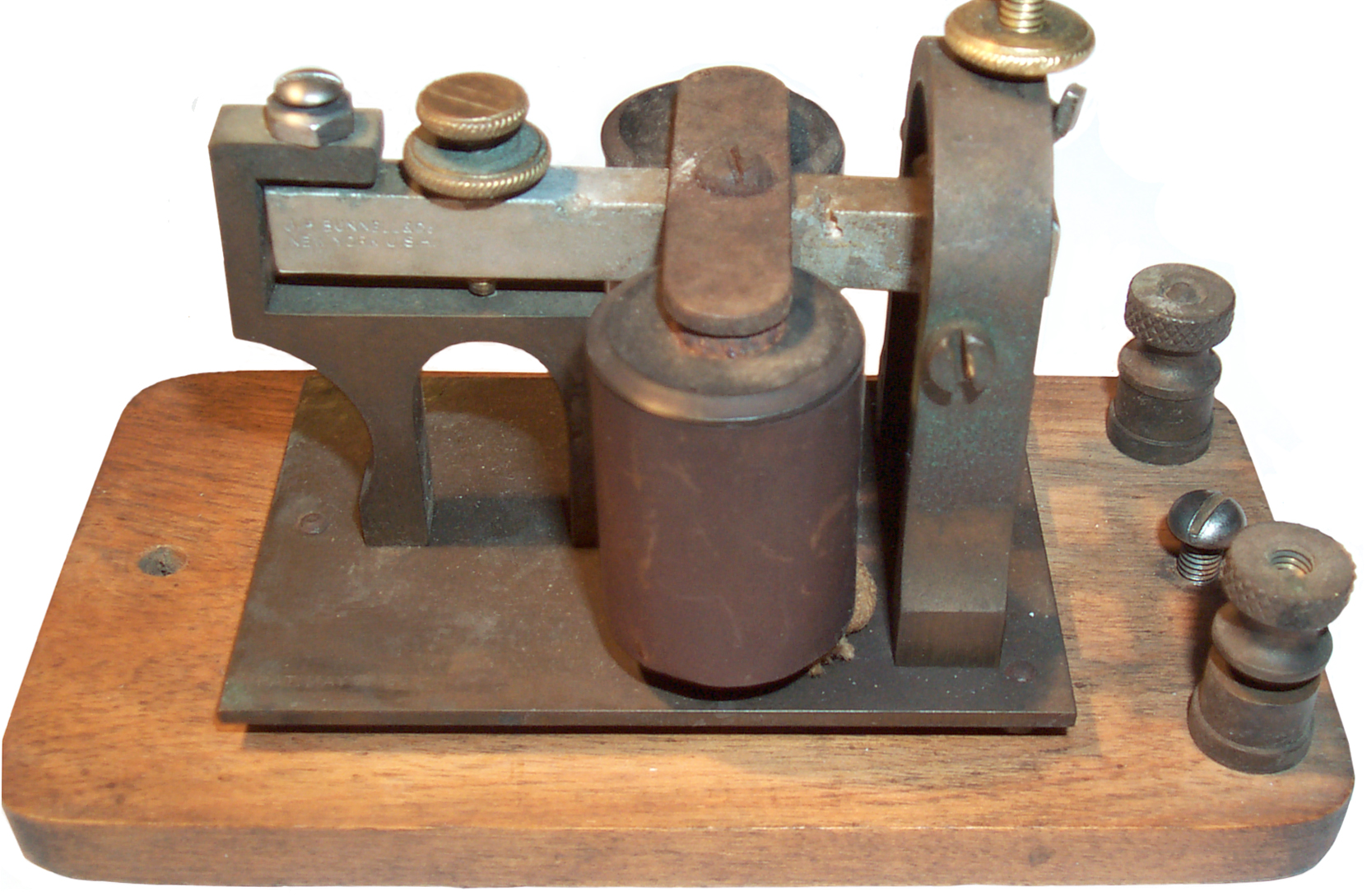
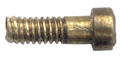
Keys
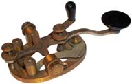
This is a Bunnell key made according to the
Bunnell
patent 237808 and is the standard
design for a straight key.
The shorting lever is an important part of the key needed to
accomplish the repeater system patented by professor Morse.
The shorting lever was also used on keys used with radios, but
there it is of little use but probably it's easier for a
manufacturer to make one product than make different versions.
Note that the frame of the key is
one of the electrical contacts and so the metal that's holding the
insulated key knob may be "hot" if the key is switching the High
Voltage.
1109310 Telegraph Key, September 1, 1914, 178/82R - bug
1110373
Relays
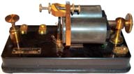
Relays were commonly used on the main line to
control the local loop. Main lines might be up to a few
hundred miles long depending on the gauge of wire used and the
quality of insulation. Larger wire is needed for longer
lines and good insulation is needed to prevent leakage currents to
ground. Also more batteries are needed.
Another use for relays is in pairs to form a repeater allowing two
way signaling on lines too long for a single loop.
The relay would have a 150 Ohm coil. The coils are 1 5/16"
diameter, larger than the 1" coils on the sounders.
The coils are wired so that their magnetic fields add. If
they were mechanically arranged in series (i.e. wire end to plain
end) then the connecting wire would be inside to outside.
But the coils are mechanically arranged with both wire ends
pointing down (looks better) so the connecting wire is inside to
inside (could also be outside to outside). This way the
reversal of mechanical position and the reversal of the wiring
results in aiding magnetic fields.
There's a fine wire connecting the armature frame to the armature
hinge. What is it for? Ans. there is a small hole
nearby in the moving armature and the wire is meant to connect
between the frame and armature so that the switched current does
not need to travel through the joint. Need to find a small
brass screw to replace it.
The coils can be moved back from the armature to allow for leakage
resistance to ground during storms or on poor quality lines.
Also the spring is missing.
The adjustment that moves the coils away from the armature is used
to counter the effect of leakage currents on the line. With
no leakage the most sensitive position would be with the coils
close to the armature. But with leakage you need to move the
coils away from the armature.
Note that there are two coils instead of a single coil. This
is done to increase the amount of magnetic field for a given
amount of wire. Winding more wire on a single coil does not
add as much field as using that wire on a second coil. In
many applications you will see dual coils.
The core for a common electromagnet is "soft" iron. Meaning
it's easy to magnetize. The higher the initial permeability
the better. There are some patents for iron alloys that work
better than just plain iron. It may be that a good
electromagnetic would make a good flux gate sensor.
28274
Telegraph-Relay Instrument, A.G. Holcomb, 361/206 ; 178/102 - dual
coils & magnet with bi-polar drive
29247
Improvement in Telegraphic Repeaters, J.J. Clark, Juy 24, 1860,
361/191 ; 178/71.13
162633
Duplex Telegraph, T.A. Edison, April 27, 1875, 370/276 -
480567
Duplex Telegraph, T.A.
Edison,Aug 9, 1892
Pole Changer
A relay that reverses the battery
polarity powering the telegraph line. Typically used for
duplex or quadraplex circuits.
379062
Pole-Changer, E.M Hamiltion, Mar 6, 1888, 361/246 - does not use
a permanent magnet
an example of a clock face pole changer is on the
Reverse Time Page -
Western
Electric Pole-Changer Relay
The relay contacts were behind a round glass which looked sort
of like a "clock face".
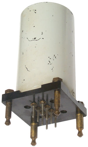
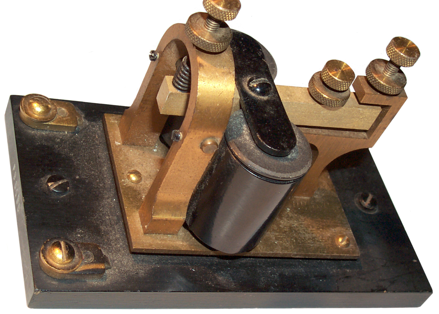
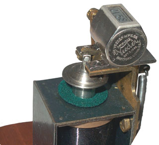
255A Polar Relay
By combining a permenant magnet with the magnetic field from the
coils the direction of movement of the armature depends on the
polarity of the input. Polar relays were used in many
applications, and I'm trying to find out the application for this
model. Also what the adjustments do.
The coils of this model can be connected directly to the RS-232
output from a computer COM port (RS-232 is a bi-polar
signal). The points can switch the loop current for a RTTY
machine where the loop voltage is on the order of 200 Volts.
This might also be used to allow a computer to drive the
WU5A stock ticker.
I've been told this is a specalized version of the WECo 280-type
relay. The plug-in base is for use in teletype equipment.
1578707
Electromagnetic Device, W. O. BECK (Western Electric), Mar 30,
1926,
335/81 ; 200/303; 335/83; 335/86; 439/680 - very
close to this one
Pin
|
Function
|
1
|
Common
contact
|
2
|
Coil 1
*
|
3
|
Coil 2
*
|
4
|
Positive
(Mark) contact
|
5
|
Negative
(Space) contact
|
6
|
Coil 2
|
7
|
Coil 1
|
8
|
n.c.
|
For RS-232 drive jumper 3 to 7 and drive 2 & 6. Use 1
& 4 to interrupt the TTY loop. This wiring draws 70 ma @
10 volts. Once the relay has changed states it stays where
it was left after the drive has been removed. But it seems
to stay in one position more than the other. The adjustments
might improve that.
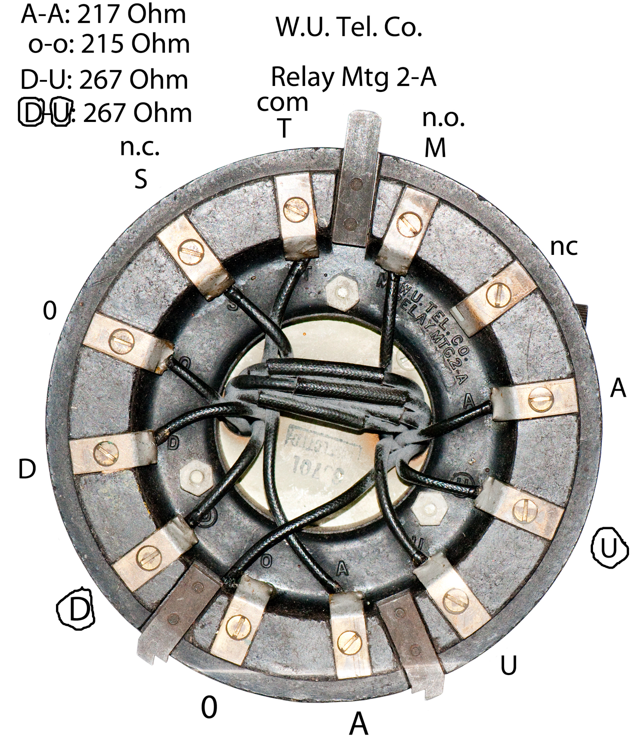
17-B Polar Relay
This is a SPDT relay with 4 coils.
The top label reads:
WU. Tel. Co.
Polar Relay 17-B
Pat'd 12-14-15 Others Pending
Mfd by Westinghouse Electric & Mfg Co.
Newark Works, Newark, N.J. U.S.A.
Notice that this polar relay has a "U" magnet and the 255 polar
relay just above also has a "U" magnet.
1160097 Telegraph Repeater, W. Finn
(Western Union), Nov 9 1915, 178/71.5 - for high speed (not hand
sent) telegraph
1164273
Relay and repeater,
William
Finn,
WU,
1915-12-14, -
RE14304 Relay and Repeater, W. Finn
(Western Union), May 22 1917 - was 1164273
1164274
Telegraph-repeater,
William
Finn,
WU,
1915-12-14, -
Polar Relay Patents
702339
Telegraphic Apparatus (tape punch), Sidney George Brown, Jun 10,
1902, 178/92; 83/70; 83/575- better detection of long cable
signals by reversing the current.
1150326
Electromagnetic Recording Apparatus for Telegraph Circuits, A.H.
Annand, Aug 17 1915 -uses polar relay.
1160097
Telegraph Repeater, W. Finn (Western Union), Nov 9 1915, 178/71.5
- for high speed (not hand sent) telegraph
RE14304 Relay and Repeater, W. Finn
(Western Union), May 22 1917 -
1163883
Selective Signalling Device, SPC Boswau, (Western Electric Co),
Dec 14, 1915 - part of a step by step system
1164069
Call Box, A.A. Clokey (Western Union)
1164273
Relay and repeater,
William
Finn,
WU,
1915-12-14, -
1164274
Telegraph-Repeater, W. Finn (Western Union), Dec 14 1915,
178/71.13 -
1350193
Attachment for Cable Recorders, F.S. Whitney, Aug 17 1920
1749738
Automatic Stroke Corrector Circuit, A.J. Finn & P.L. Myer
(Western Union), 178/70.00A, Mar 4, 1930
2212634
Relay Testing Method and Apparatus, W.D. Buckingham (Western
Union), Aug 27, 1940, - uses CRT to test polar relay
2592779
Tape Controlled Telegraph Transmitter, R.J. Wise, R.D. Parrott
(Western Union Telg Co), Apr 15, 1952 -
single row with dots & dash
photocell
Calls:
RE18756
Resistor Cell Circuit, C.F. Jenkins (Jenkins Labs), Mar 7 1933 -
was 1693509
836710 Line Printing Slug
1144236 Transmitter or Reproducer, W.E. Peirce - single line dot
and dash sender from paper tape
1326864 Selective Controlling Apparatus for Electric Circuits -
player piano
1826858 Photographic Printing Apparatus - motion pictures
1953072 Remote Control Advertixing and Electric Signaling
System, - optical read 5 level punched paper tape
1972555 Kinetographic Apparatus - movie related
1981255 Motion Picutre Projector
2064049 Combined Motion Picture & Talking
2064050 Sound Gate
2177077 Photoelectric Transmitter
2266349 Method of Producing Holes . .
2307099 High Speed Teelgraph System, G. Apperley (RCA), -
optical
2313583 Modulating System
2317850 Electro-Optical Facsimile Synchronizing System - drum
fax
2332142 Long Dash Interrupter, (RCA) -
2353608
Printing Telegraph Apparatus, W.J. Zenner (Teletype Corp), Jul
11 1944, 178/42; 226/45; 226/196.1; 242/615.3 -
center traction holes and dots
on one side and dashes on the other side
Calls:
1997601 Automatic Control Mechanism, A.H. Reiber (Teletype
Corp), Apr 16 1935 - taught tape punch to reader
2382251 Telegraph Perforator-Transmitter (Bell Tel), - 5 level
2403918 Method of Operating the Electronic Chronographs, (RCA)
Track Relay
This is a railroad track relay, not directly related to
telegraph equipment. The rail system is broken up into
blocks that are insulated from the adjacent blocks. Train
wheels are made in pairs connected by a very strong axle so form
a low resistance path between the tracks.
YouTube: Feynman: How the train stays on
the track -
The Track Relay is used to sense if a train is in the block.
Since this relates to safety is sometimes called a Vital
Relay.

|
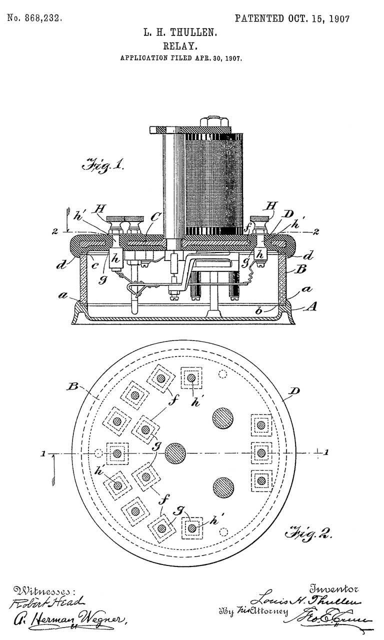
868232
Relay, Louis H. Thullen, Union Switch &
Signal Co, Oct 15, 1907, - |
|
886740
Relay for signaling apparatus, Louis
H Thullen, Union
Switch & Signal Co,1908-05-05, -
Wheel mechanism rather than conventional relay
armature. Used where one frequency is used for
propulsion and a different frequency is used for
signaling.
|
|
891303
Signaling system for railways, Louis
H Thullen, Union
Switch & Signal Co, 1908-06-23, -
two blocks shown.
"My invention relates to signaling systems for
railways and especially for electric rail ways the
trackway of which forms part of the return for the
alternating current used." |
|
916505
Relay, Louis
H Thullen, Union
Switch & Signal Co, 1909-03-30, -
"An object of my invention is to have the releasing
point of the relay substantially the same as its
picking up point" |
|
1985577
Railway Track Circuits, B.
Mishelevich, Union
Switch & Signal Co, Dec 25, 1934, -
Simple single relay, single block
|
Dial Telegraph
Similar to a clock face with a
single hand that can point to all the letters of the alphabet the
digits 0 through 9 etc.
See separate web page
Dial
Telegraph.
Sounders
Sounders were the most common means
of receiving telegraph signals by 1859.

4 Ohm sounders are for
local loops (under say 100 feet) and practice boards. 20 Ohm
sounders are for up to 15 mile lines. Higher (say 150) Ohm
sounders are for very long lines.
This is Bunnell serial number 62 as received. So far I've
found 4 parts all with the number 62 stamped on them so assume
that's a serial number. All the brass has tarnished and the
coils test open. The coils are OK just a bad connection to
the terminals.
The lever are is marked: J.H. Bunnell:?? New York. U.S.A.
On the bottom of the wood is the marking:
I.R.S. 11 18 which may mean Internal Reapir Station Nov
1918
The modern screw and nut on the yoke is a 6-32 that's a sloppy
fit. The correct thread is a 6-40.
I have taken this sounder apart and am polishing the brass and
after steel wool on the wood treating it with Tru Oil gun stock
finish.
Then plan to use Everbright on the brass. The steel will be
painted flat black.
The 8-40 tap worked to chase the thread and now the stop and lock
nut fit properly.
Non Interchangeable parts
An interesting thing about this sounder is that the dimensions are
not close to common rounded dimensions. The O.D. of the coil
covers is very close to 1 inch, but all the other dimensions seem
strange (not metric). Maybe the number "62" that appears on
many parts relates to a bin number for selective assembly rather
than a serial number? Or maybe it's the employee number of
the man who made it?
Note it was not until the end of the Civil War (1861 - 1865) that
tolerances and interchangeable parts started to appear in the
U.S. So prior to 1861 telegraph equipment would be made by
skilled craftsman and would not have interchangeable parts.
It wasn't until 1864 that the U.S. adapted the National Coarse
(NC) and National Fine (NF) thread specifications. Prior to
that each shop probably used whatever they had on their lathes.
Machine
Tools Time Line by the ASME

This Western Electric sounder has 1 1/16"
O.D. coils and is marked "Sounder 3C 140 Ohms" and "F9003C".
On the bottom it has the two conical feet like the above sounder
and has a couple of wooden rods with mounting screws through them
like the above sounder. This one is complete and the coils
test good as received.
It may be that the Main Line sounder was a development of the late
1800s that was intended to replace the need for the relay.
Note that with a sounder that would work directly on the main line
things get much simpler. A relay can only be used in one
direction so needs either an operator between the two end stations
or seperate wires for send and receive. In either case a
main line sounder would be a big cost savings.

This sounder is a 20
Ohm Bunnell and looks very similar to the 4 Ohm soundere
above. But it does not have the 1895 patent (
see below) notice on the brass reasonator
plate. The coils are larger at 1.3" OD.
The lever is marked J.H. Bunnell, New York.
In the early days of telegraphy a relay was used on a long line
and then 4 Ohm sounders can be used in the local loop.
Battery was typically supplied at each end of a line by either
Gravity and later Leclanché cells. The number of cells goes
up like one cell per mile of line and per sounder.
A good Sounder makes noise when a
feeble current is present. So a figure of merit might be how
much sound it makes and what is the minimum current needed for
good operation.
A sensitive relay might also be driven my the main line and then
the relay contacts would drive a local 4 Ohm Sounder. Since
the mass of the relay armature is much lower than that of a
Sounder, it would operate with less current hence be more
efficient.
A practice board can be run from a single wet battery (i.e. a
little over 1 volt).
5 1/2" x 3" base sounders
No.
|
Description
|
Coil
Ohms
|
Pull In
ma
|
Trunion
End Play
|
Armature
Air Gap
|
3A
|
|
|
<
120
|
.015
|
.016/.005
|
3B
|
Local Battery
|
20
|
< 50
|
.015 |
.016/.005 |
3C
|
Main Line
|
140
|
< 20
|
.015 |
.016/.005 |
3D
|
|
|
< 42
|
.015 |
.016/.005 |
3E
|
|
|
< 10
|
.015 |
.016/.005 |
4A
|
Local Duplex (2 metal
contacts)
|
20
|
|
|
.016/.005 |
12521
|
|
|
< 65
|
.024
|
.016/.005 |
159894
Telegraph-Sounder, J.H. Bunnell, Feb 16, 1875 - see patents
190191
Telegraph-Sounders, J.H. Bunnell & M.W. Goodyear, May 1, 1877
- lower cost, easier for beginners
180700
Printing Telegraph, J.H. Bunnell, Aug 8, 1876 - really a stock ticker
255932
Mechanical Telegraph Sounder, J.H. Bunnell,Apr 4, 1882 - telegraph
key knob on sounding bar & no electromagnet.
267833
Telegraph-Sounder, J.H. Bunnell,Nov 21, 1882 - wood sounding board
mounted in cast iron base.
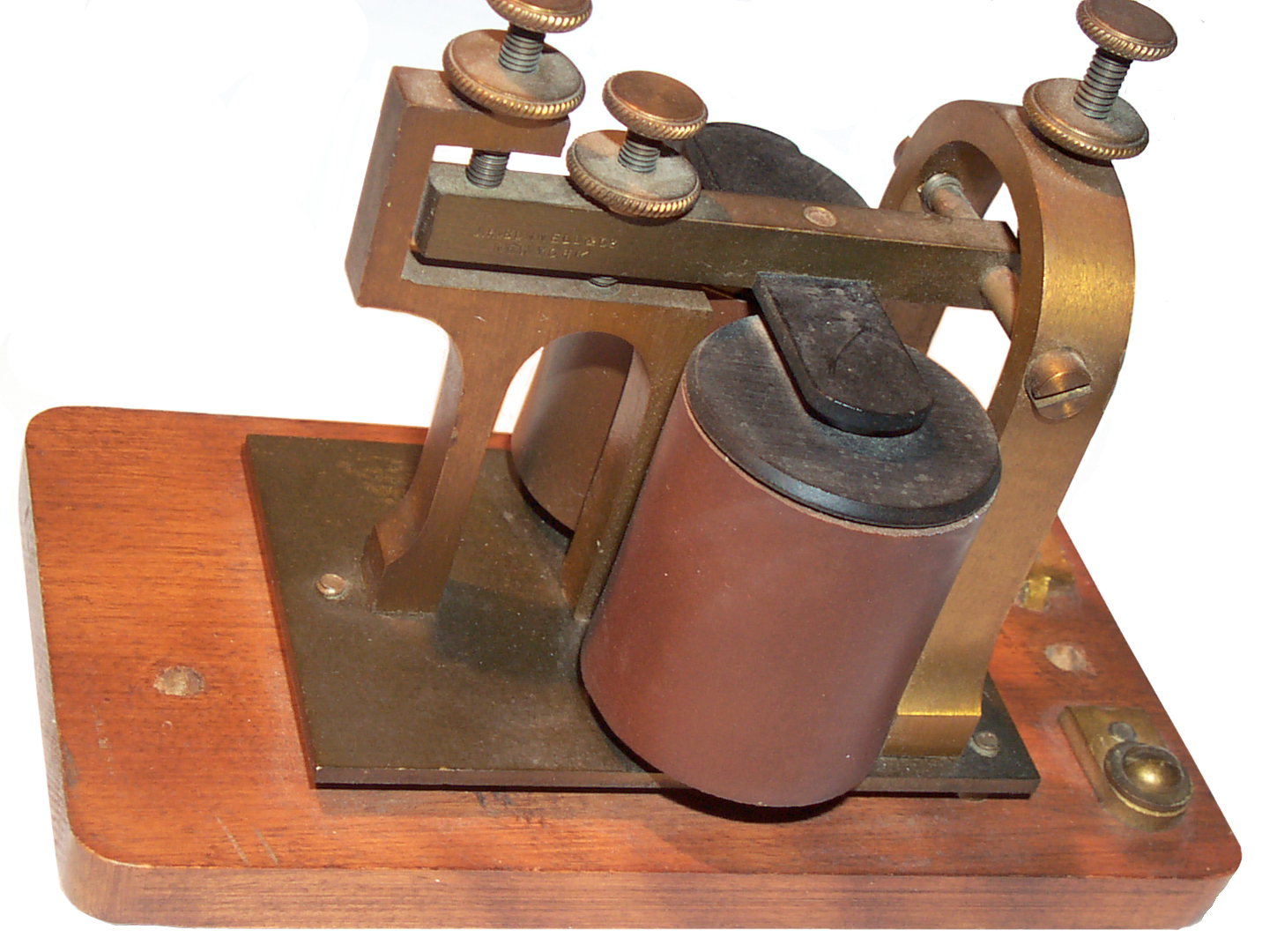
Veeder Counter
This was the first of a number of "counters" and
"registers" patented by Mr. Veeder. This one is a general
purpose design that can be used in many applications.
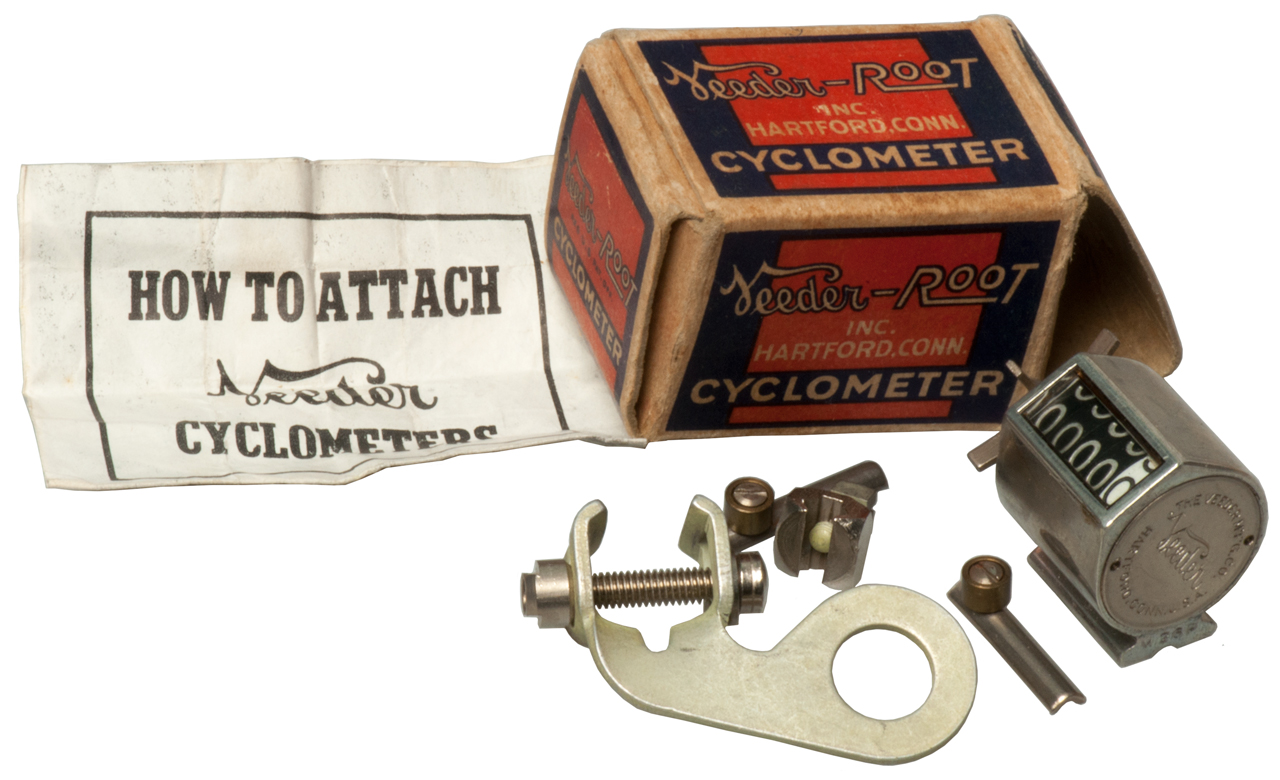
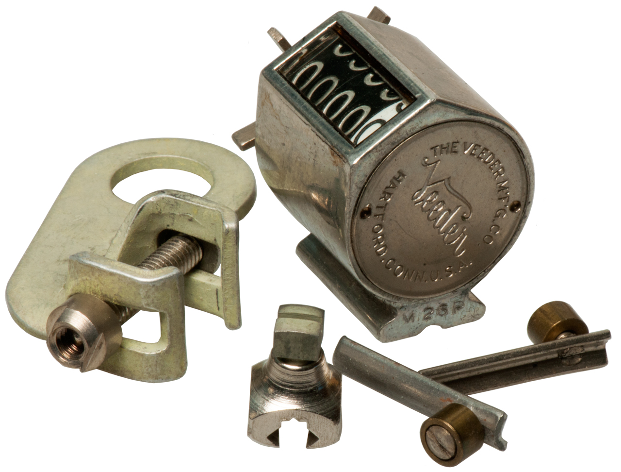
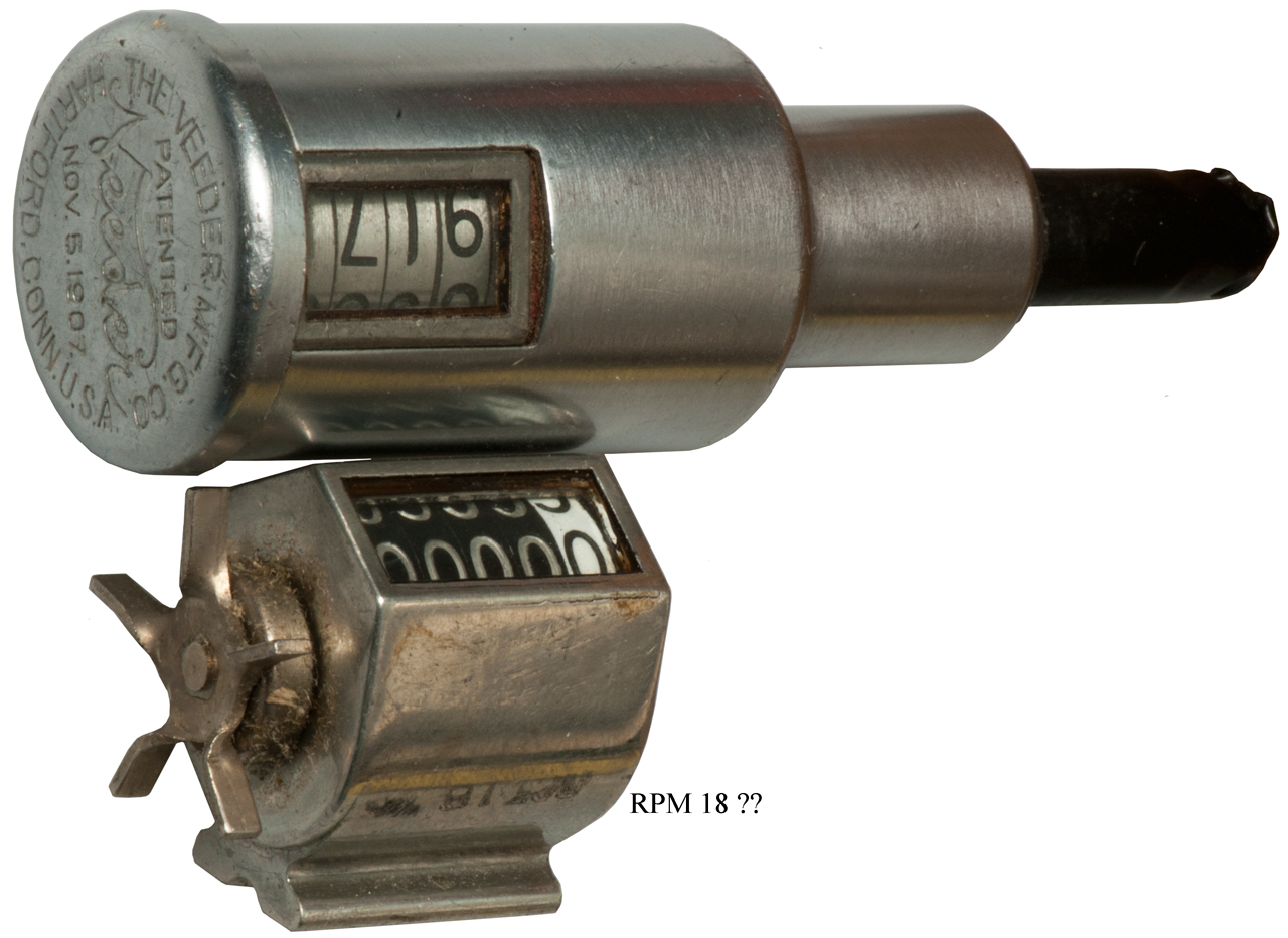
The Cyclometer and Speed-indicator are both marked Veeder Mfg Co.
not Veeder-Root. But the box and Directions for the
Cyclometer are marked Veeder-Root Inc.
372994 Velocipede-saddle, Cuetis
Hussey veeder, Nov 8, 1887, 297/205 -
close to the modern spring wire narrow type still used.
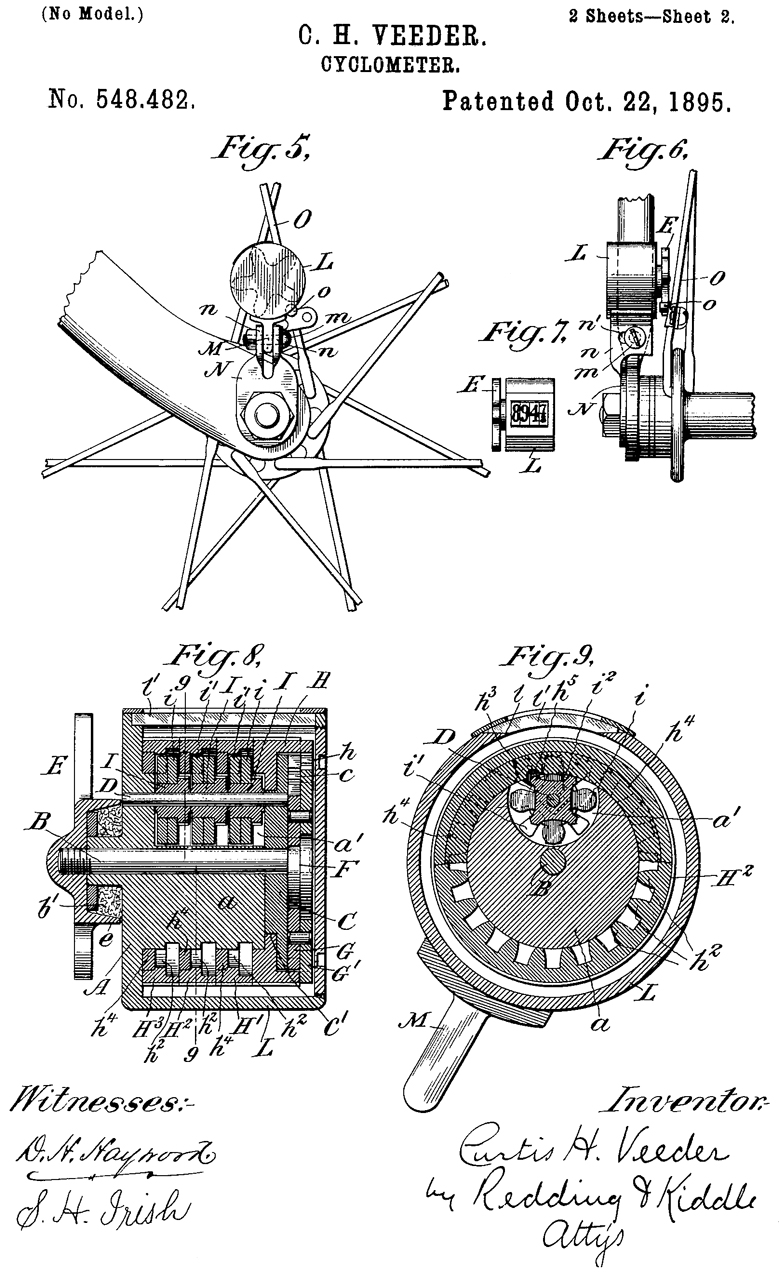
D28078 Design for a case for registers, Curtis
Hussey Veeder (Wiki),
The
Veeder Manufacturing Company, Dec 21,
1897, D10/97; D10/70 - outer case for patent 548482
Cyclometer.
676519 Register, Curtis
Hussey Veeder, Veeder
Mfg Co, Filed: Nov 21, 1898, Pub: Jun 18,
1901, 235/97; 235/110; 235/117R; 235/144R; 235/144S;
235/47 - dual counters, one of which can be reset (like the trip
and odometers in a car).
634073
Registering-Counter, Cuetis
Hussey Veeder, The
Veeder Mfg Co., Filed: May 17, 1899, Pub: Oct 3,
1899,235/117R ; 235/1C; 235/139A; 235/139R - a single
general purpose counter (note filed after the above patent)
732975 Tachometer, Curtis
Hussey Veeder, Jul 7, 1903, 73/500 -
not based on counters, but rather an analog instrument
733358 Tachometer, Curtis
Hussey Veeder, Jul 7, 1903, 73/496;
73/500 - an analog instrument based on a vane type pump
741420 Odometer, Curtis
Hussey Veeder, Veeder
Mfg Co, Oct 13, 1903, 235/95R;
235/96 - sealed against the elements and can work quickly (not
clear what vehicle it's for, maybe bicycle or automobile?)
740492 Machine for cutting off metal rods,
&c., Curtis
Hussey Veeder, Veeder
Mfg Co, Oct 6, 1903, 83/199;
292/337; 82/59; 82/70.2 - can cut short lengths of rod from a
spool without burs
751576 Steering mechanism for motor-vehicles, Curtis
Hussey Veeder, The
Veeder Manufacturing Company, Feb 9,
1904, 280/90 - adds hydraulic damper
826630 Tachometer, Curtis
Hussey Veeder, Jul 24, 1906, 73/500 -
an analog instrument based on a vane type pump
833355 Driving mechanism for odometers, &c., Curtis
Hussey Veeder, Oct 16, 1906, 235/91R;
235/95R; 74/423; 74/810.1 - allows the odometer to be located on
the dash board (this was before there were instrument panels)
rather than at the wheel.
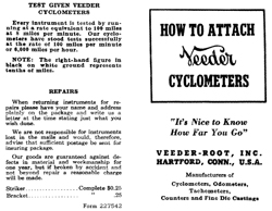
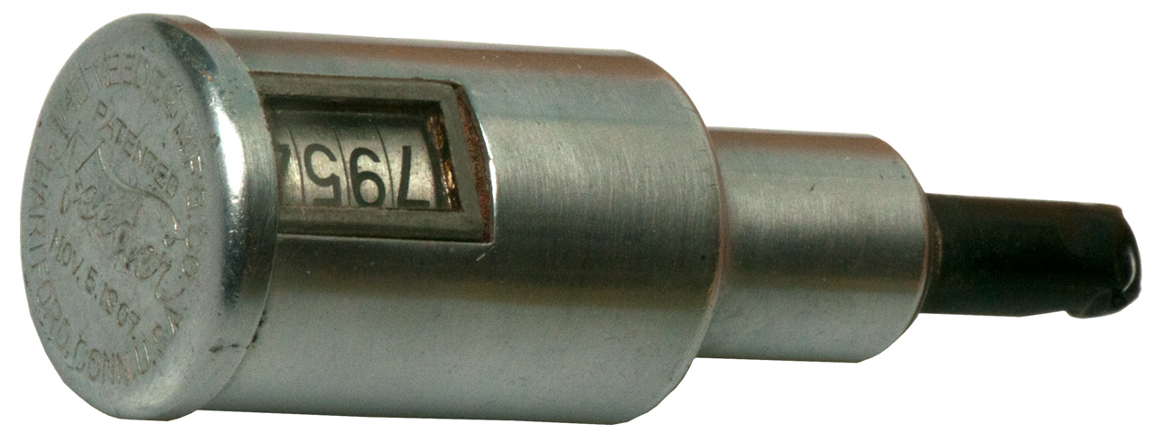
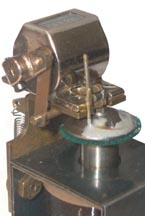
Veeder Speed Indicator
This counts shaft turns and has a quick start and quick stop
feature built-into the spring loaded input shaft. If it is
held on the shaft for 60 seconds (a long time) then the reading
would be RPM.
But if held for 6 seconds the reading can be multiplied by 10 to
get RPM.
For a chronometric tachometer see Cars \ Chronometric
Tachometer

|
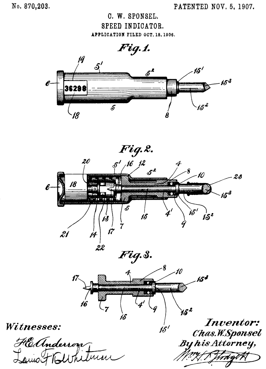
870203
Speed-indicator, Charles
W Sponsel, 1907-11-05, - 235/103 - 5 digit turns counter used with
clock, stopwatch, &Etc. |

|
The drive shaft is spring loaded and needs
to be pressed into the counter body in order for the count
to increment. The clutch (16) allows for quick
starts and stops to get a more accurate turns count.
|
937015 Measuring or indicating instrument, Curtis
Hussey Veeder, Veeder
Mfg Co, Oct 12, 1909, 73/500 -
improvement on 732975 & 733358 (see above), but still an
liquid level tachometer, but counter added as odometer.
950546 Counter, Curtis
Hussey Veeder, Veeder
Mfg Co, Mar 1, 1910, 235/144PN;
235/117R; 235/144S; 246/191 - zero set mechanism
950601
Register, Samuel
Warren Potts, Veeder Manufacturing Co, 1910-03-01, -
1000860 Register, Curtis
Hussey Veeder, Veeder
Mfg Co, Aug 15, 1911, 235/96 - cites his prior patents 548482
& 676519
1000861 Odometer, Curtis
Hussey Veeder, Veeder
Mfg Co, Aug 15, 1911, 235/95.00B - hub mounted, like used
on truck axles
1002016 Odometer, Curtis
Hussey Veeder, Veeder
Mfg Co, Aug 29, 1911, 235/95.00B - hub mounted, like
used on truck axles
1016906 Tachometer, Curtis
Hussey Veeder, Veeder
Mfg Co, Feb 6, 1912, 73/500 - liquid level tachometer,
but counter added as odometer.
1015710
Setback-counter, Samuel
Warren Potts, Bristol
Co, 1912-01-23, -
1015767 Tachometer, Curtis
Hussey Veeder, Veeder
Mfg Co, Jan 23, 1912, 73/500 - liquid level tachometer,
but counter added as odometer.
1081561 Hub-odometer, Curtis
Hussey Veeder, Dec 16, 1913, 235/95.00B,
301/108.2 -
1093580
Setting glass, Curtis Hussey Veeder, Veeder Mfg Co, Apr
14, 1914, 52/204.62, 52/482 - how to fit glass window
on his counter to make it weather tight
1125607 Hub-odometer, Curtis
Hussey Veeder, Veeder
Mfg Co, Jan 19, 1915, 235/95.00B - hub mounted, like used on truck
axles
1196495 Register, Cuetis
Hussey Veeder, The
Veeder Mfg Co., Aug 29, 1916, 235/91.00R,
235/95.00B, 235/1.00A - on pumps, like used for
gasoline
1149605 Manufacture of pawl-frames, &c., Cuetis
Hussey Veeder, The
Veeder Mfg Co., Aug 10, 1915, 72/324,
72/371, 29/893.2 - for use in his counters
2152394 Astronomical mirror, Veeder
Curtis H, Mar 28, 1939, 359/849
- a truss system rather than solid
glass for large mirrors with lower weight
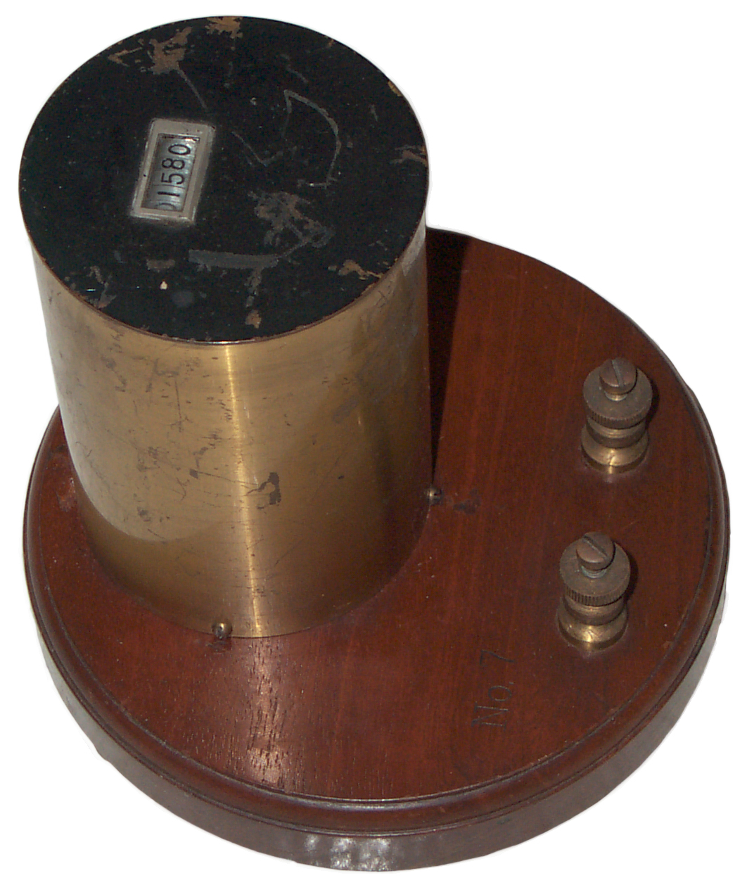
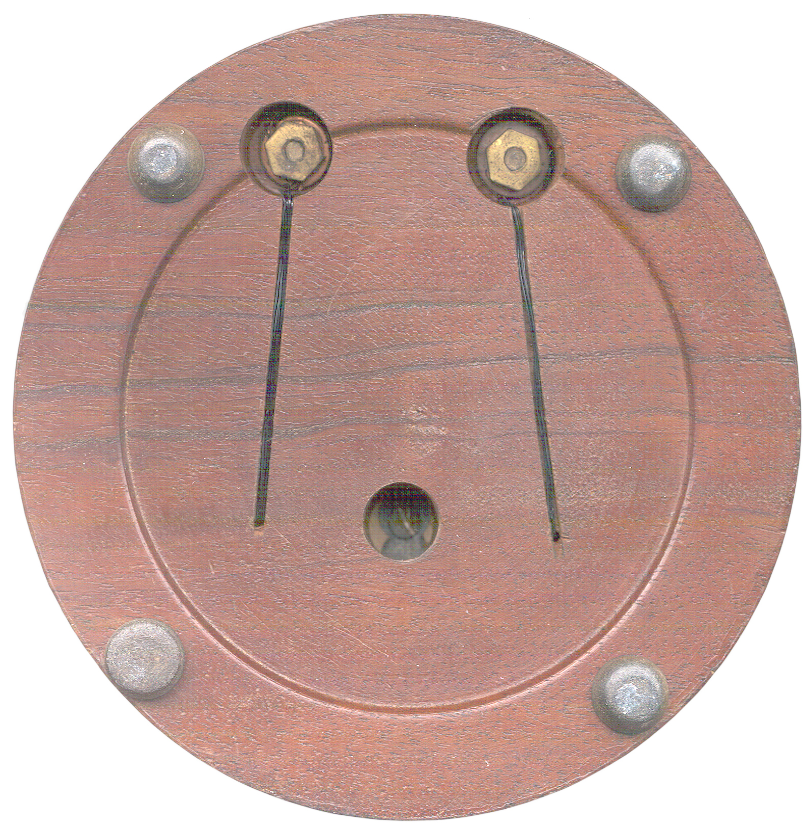
This Electro-Mechanical counter has No. 7 engraved
(stamped) into the wood just above the left binding post. Brand
name is Veeder. Patented Oct 3, 1899.
 |
634073
Registering-Counter, Cuetis
Hussey Veeder, The
Veeder Mfg Co., Filed: May 17, 1899, Pub: Oct 3,
1899,235/117R ; 235/1C; 235/139A; 235/139R - a
single general purpose counter (note filed after 676519
Register). |

|

|
|
No.
7 Electro-Mechanical counter
|
The
counter proper looks like the hand held type.
No provision to reset.
|
|
634073
Registering-Counter, Oct 3, 1899, Cuetis
Hussey Veeder, The
Veeder Mfg Co., 235/117R ; 235/1C; 235/139A; 235/139R
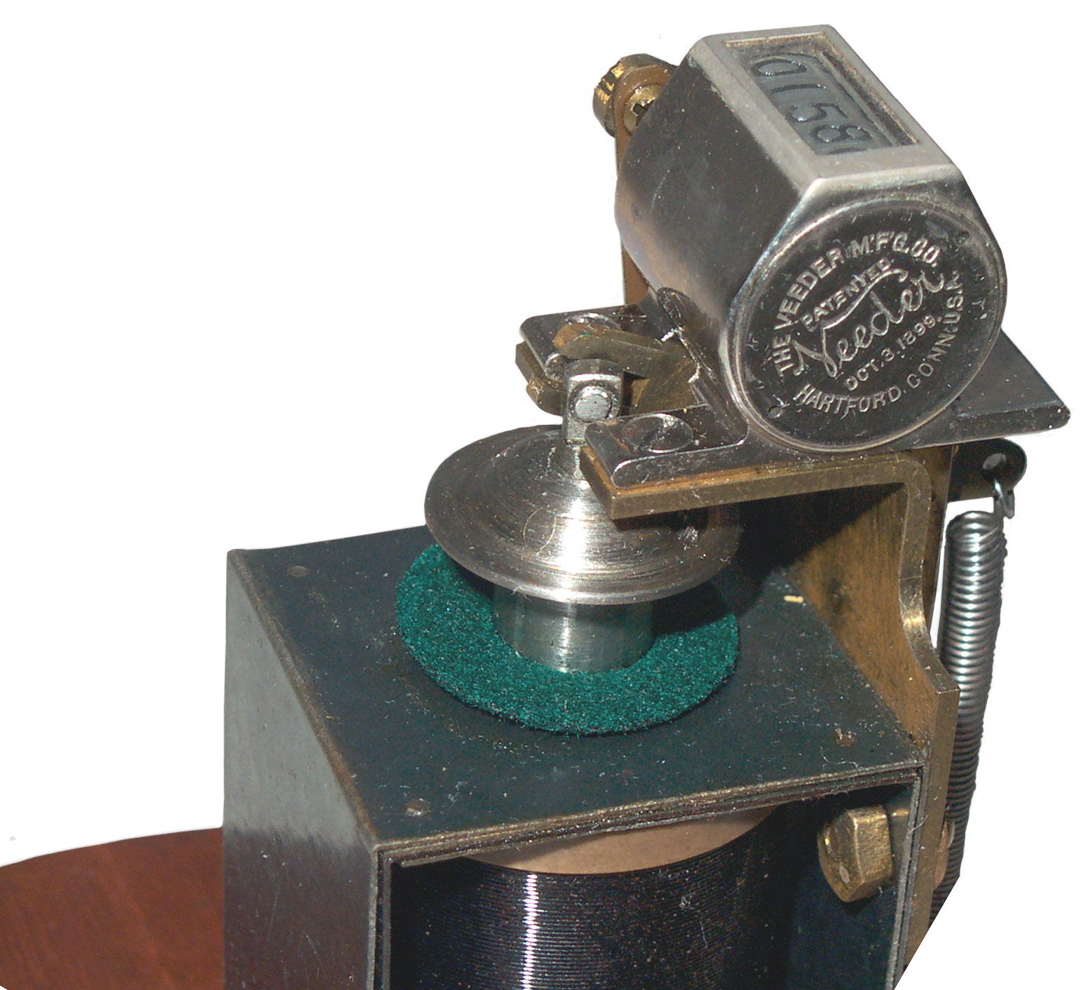
The counter is a ratchet type where the lowest digit increments ten
counts for each turn of the input shaft. This type of counter
shows up in all kinds of things. Later called Veeder-Root
counters. For this application the lever translates the
armature throw into 1/10 of a trun of the counter shaft.
Coil about 2 Ohms takes about an amp to actuate the mechanism.
There are maybe 5 wires coming from the coil all soldered toghther,
i.e. the coil consists of 5 different coils connected in
parallel. This was a way to get a lower coil resistance with a
much higher fill factor than you could get if you used a larger
diameter wire. The individual wires running under the base are
about 0.014" dia. Probably AWG 28 which is 65.1 Ohms/k', so 10
Ohms would take 154 feet for each of 5 coils or 768 feet. The
former is 1.600" long and the coil O.D. is 1.22 the I.D. might be
0.5" making for a window of 1.6 x .36 which can hold just under
3,000 turns which might amount to 600 feet of wire, so in the ball
park.
But the spring is not pulling the arm high enough to let the ratchet
pawl drop into the next notch so the count does not always
advance. This is caused by the electro-magnet core rotating
and jamming the works.
Some problems:
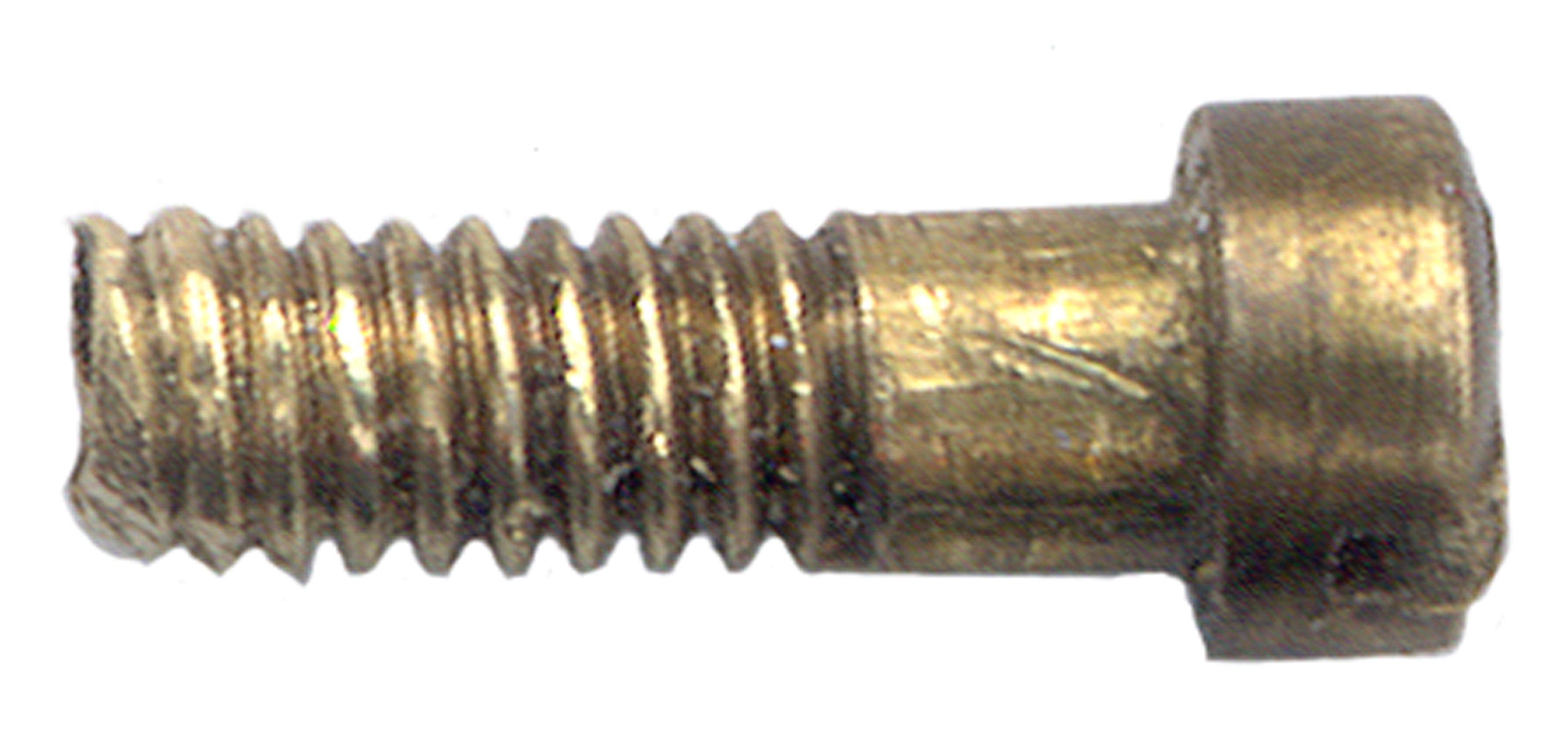
The brass lever arm is bent (marked "7")
The hinge screw has bunged up 2-56 threads at the tip -
This is because after the screw was
installed the thread end was expanded
to lock it in place. This can clearly be seen on the two
screws that hold the
bracket to the electro-magnet. No Loctite then.
The brass hinge screw has a rough
surface where the lever pivots
Both the screw and lever are brass, better if one is a different
hardness
There is nothing to keep the armature from turning and that
promotes jamming the lever. There are grooves on the
cylindrical part of the armature, but no sign of something to ride
in the groves. Also on the bottom of the wood base there is
a clearance hole that's extended up through the disk at the base
of the electro-magnet to give access to a screw that goes into the
bottom of the electro-magnet.
Why?
"I suspect that it's an adjustable stop for the solenoid core." -
David B.
7 Aug 2007 - 2-56 tap and die arrived so could clean up threads on
screw (photo above) and it's hole in the bracket.
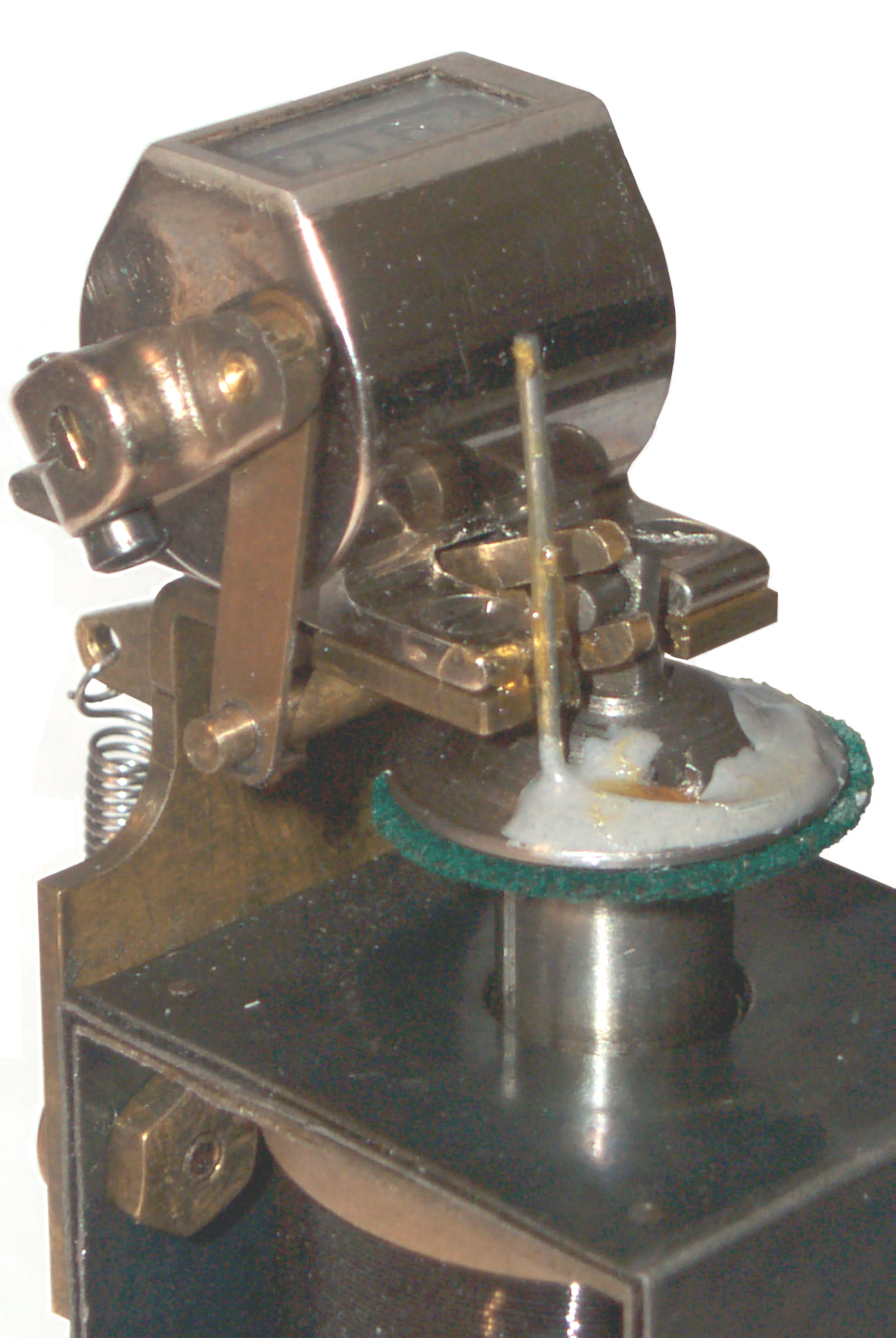
The fix was to stop the plunger from rotating. It does have
shallow grooves in two places, but I don't see anything to ride
the grooves. Maybe it was hidden from view and wore
out. The fix was to epoxy a paper clip to prevent
counterclockwise rotation, which seems to be the only direction.
Some grease on the paper clip and clock oil on the joints and a
tiny bit of weak Loctite applied in the female threads so
that only the last turn of the screw will see the Loctite.
That way the screw won't back out, but could be removed for future
work.

Still don't know what the bottom center screw is for and why it's
accessible when the unit is assembled.
Why?
A single "D" cell flashlight battery will not do anything, but two
connected in series does cause the counter to work smartly.
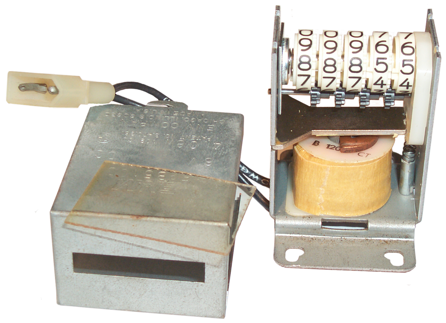
ENM Electromagnetic Counter
Engraved into the metal case:
ENM
E2B516D
6V DC
4.08W 109CJ (SA)
Patent No. 3470361
ENM Company
Chicago, Illinois 60630
Made In U.S.A.
It works smartly at 5 volts and sluggish at 3.3 volts.
3470361
Counter, B.J. Wollar (ENM), Sep 30, 1969, -
a lower cost counter (than that
above) aimed at things like photo copiers or vending machines.
in the photo above the armature is the sheet metal part just
above the coil. The plastic part on the right gets pulled
down
and has grooves facing the fast wheel that act as an
escapement. Below and between each wheel is a gear free to
turn on a shaft. As a wheel increments from 9 to 0 a
single tooth engages the gear and moves the adjacent wheel 1/10
of a turn. At all other positions of the wheel the gear is
frozen (the single tooth is more of a notch than a projection).
A copper clip holds the coil down. The copper clip has
been deformed so that it clamps the notch in the coil's central
core.
4143749
Totalizer for Vending Machine,
3580498
Electromagnetic Counting Mechanism,
3761015
Electrical Impulse Counter with Shock proofing Mechanism
4270399
Counter Drive Mechanism,
3700163
Star wheel Operating Mechanism
Connectors
439 Electrical Connectors
/623 Cable Composed of Mutually
Insulated Conductors Having Separately Carried Conductor end
Terminals
/651 With Insulation other than Conductor Sheath..Two or more
plural-contact coupling parts combined in one integral
unit...Unit includes receptacle for receiving plug having
spaced, longitudinally engaging, prong-like contacts....Combined
with plug having spaced, longitudinally engaging, prong-like
contacts
/736 With Insulation other than Conductor Sheath .Metallic
connector
or contact secured to insulation..Secured by heat-molding or
cold-deforming insulation or by casting, welding, or cementing
/805
/808 Metallic Connector or Contact having Moveable or Resilient
Securing Part.Screw-thread operated securing part..With strand
coiling or loop forming means
/828 Metallic Conductor or Contact
Having Movable or Resilient Securing Part.Spring actuated or
resilient securing part..Clamping pressure provided by
cantilevered finger resiliently urged away from opposed clamping
member ...Pivotally or rotatably mounted member locks or places
securing part into securing condition
/866 Metallic Conductor Terminal
having Conductor Sheath Engaging Means.Pin or plug type terminal
/874 Metallic Connector or Contact Having part Permantently
Secured to Conductor using Fused or Molded Material
403 Joints and Connections
/274 Member Deformed in situ
Binding Post
A binding post is an improvement on a screw and nut.
In the photos above of the Veeder
counter notice that the two binding posts are made by using a
stock screw and two thumb nuts. The top thumb nut has the
common straight knurl and the bottom thumb nut has no
knurl. So it's just a screw, two thumb nuts, a washer and
a hex nut.
137810
Connecting-Post for Electrical Apparatus, T. Wishart, Apr 15,
1873, 439/817
140618
Screw-Post for Electrical Apparatus, S.D. Field, July 8, 1873
439/810 ; 256/DIG.3 - thumb screw
279274
Binding Post, W.R. Patterson, June 12, 1883, 174/94S ; 24/127;
24/130; 411/531; 439/808
296160
Binding Post for Electrical Conductors, A.G. Goodbody, April 1,
1884, 439/729
434892
Binding-Post, G.J. Scott, Aug 19, 1890, 439/807; 24/136.00B
446871
Binding Post, C.A. Lieb, Feb 24, 1891, 439/736 ; 411/389; 429/121;
439/797
137810
Connecting-Posts for Electrical Apparatus, T. Wishart, April 15,
1873, 439/817
140618
Screw-Posts for Electrical Apparatus, S.D. Field, July 8, 1873,
439/810; 256/DIG.3
297655
Binding Post, T.R. Abernethy, Apr 29, 1884, 439/807; 24/459
358518
Binding Post, G. Westinghouse Jr., Mar 1, 1887, 439/812
416288
Binding Post, P.B. Delany, Dec 4, 1889, 439/813; 256/DIG.3
582464
Electric Contact, C.C. Dusenbury, May 11, 1897, 200/507; 256/47;
310/249; 403/218; 439/814
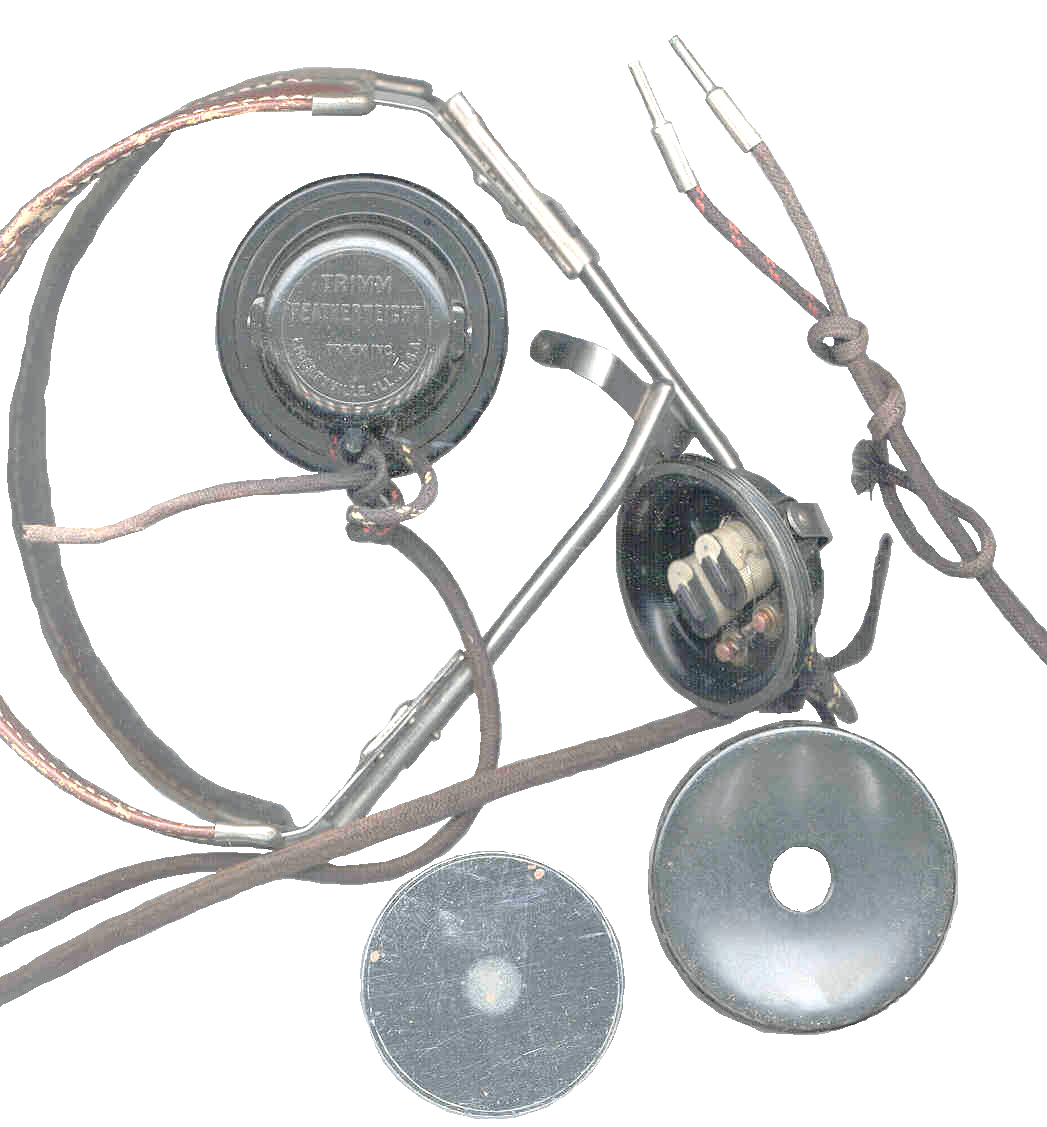
Tip

Tip pins were
the common connection used for headphones starting for the
earliest days. Later replaced by the 1/4" phone plug.
When a raw wire is connected multiple times it tends to
break. I think the first connectors were ways to have a more
durable termination on a single wire. The Tip pin was the
result.
151157
Electric Conducting Cordage, T.L. Reed, May 19, 1874, 439/888 ;
174/124R
Tip pins formed
from heavy wire and the coiled cord.
199827
Tip for Flexable Electrical Conducting Cords, L.E. Heaton,
January 29, 1878, 439/866 ; 403/274
203931
Connecting Tip for Electrical Conductors, May 21, 1878, J.A.
Nickerson - oldest patent in class 439/805
but is an improvement using threads to pinch a
wire end.
208969
Tips for Switch Cords, T.B. Doolittle, Oct 15, 1878, 439/866 ;
338/332
230090
Tips for Electric Conductors, J.H.C. Watts, Jly 13, 1880, 439/866
; 439/874
repairable - prior are used a metal forming
method and can not be repaired.
295371
Tip for Electrical Conductors, G. Doolittle, Mar 18, 1884,
439/866; 338/332
317887
Flexible Tip for Conducting Cords, G.K. Thompson, May 12, 1885,
324171
Metal Tipped Electric Cord, W.H. Sawyer, Aug 11, 1885, 439/866
738545
Cord Tip, W. Kaisling,
Kellogg
Switchboard and Supply Co, Sep 8, 1903, 439/866 ; 439/623;
439/874
757192
Tip or Terminal for Electrical Wires, S.C. Houghton, April 12,
1904, 439/866
Banana Plug
The Banana plug is a high current single conductor slip fit
connector
215917
Attaching Electrical Switch-Wires to Binding-Posts, J.E. Hamilton,
May 27, 1879, 439/805
the plug is clearly shown with a
slot so that it can be a tight fit into a hole, but no mention
is made.
the plug has a cylinder form factor, not a bullet and waist
shape. The beginning, but not there.
221074
Electric Conductor, A.A. Knudson, Oct 28, 1879, 439/866 ;
174/110R; 439/825; 439/884; 439/888
coil spring
between plug and wire. Plug is a split tapered pin.
223969
Electrical-Switch Pin, J.H.C. Watts, Jan 27, 1880, 439/822 ;
379/320; 439/825
split tip with a spring to
separate the two parts, getting close, but no cigar.
2851669
Expansion Type Connector Plug, R.C. Koch, Sep 9, 1958, 439/265 ;
439/551; 439/801
1731661
Electrical Current Tap Plug or Connector, P.A. Hauenstein, Oct 15,
1929, 439/651
2713670
Electrical Jack, Jul 19, 1955, 439/551
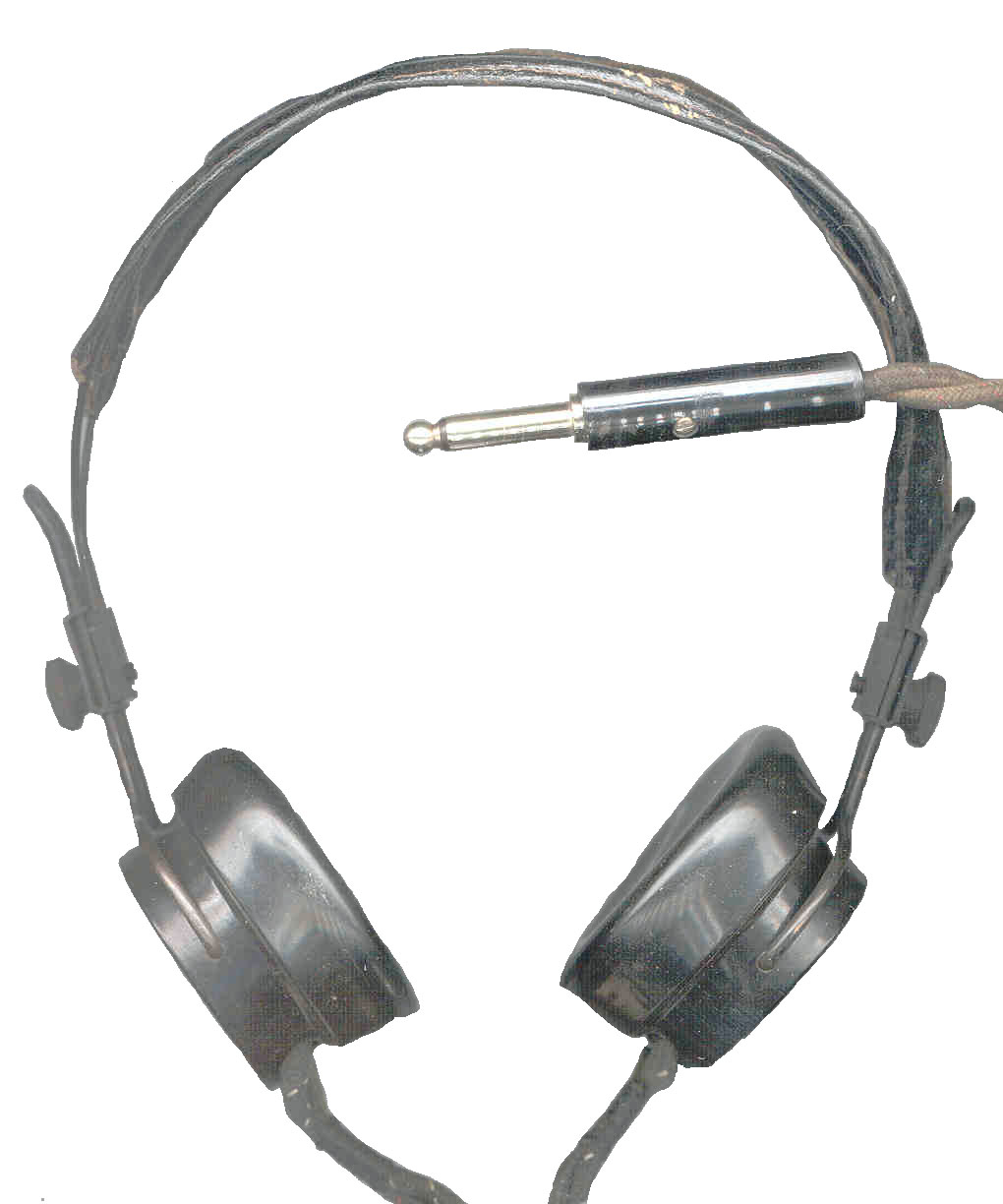
1/4" Phone Plug
Commonly available up into the 1960s were 1/4" phone jacks that
had one or more switches built into the jack. For example if
you installed a 1/4" jack on a radio that had an internal speaker
you could route the hot wire to the switched terminal and it's
associated sleeve terminal to ground. When the plug is
installed it would open the switched terminal turning off the
speaker. With the hot speaker wire to the tip the headphones
would now work. By putting a resistive divider between the
speaker hot and the tip you could make the max volume in the
headphones sort of match the speaker volume, rather than
experiencing very loud sound when first connecting.

Many of the 1/4" phone plugs were designed to accept Tip pins
which were trapped under a screw making it easy to install the
plug and not requiring a modification of the headphones.
The 1/4" phone plug was used for telephone and telegraph
connections as well as for headphones, microphones, etc.
215568
Telegraph Switch-Board, J.H. Bunnell, May 20, 1879, 361/633 ;
439/675
uses posts on
switchboard and a hollow two conductor plug very similar to the
type used on wall warts now.
219936 Coupling for Electric
Annlunciator Conductors, H.M. Green, Sep 23, 1879, 200/51.1 ;
439/819
single
conductor, but the right shape plug
310750
Combined annunciator and spring-jack, Louis Townsend,
1885-01-13, - electromagnet coil wound over jack barrel
(oldest "spring jack" in title. single conductor
Terminal Plug Attachment for Flexible Cords, Sep 17, 1889, -
single conductor, but 1/4" plug shape
279/7 ; 279/35; 279/36; 403/290; 411/433;
411/918; 439/805
jaws grab the wire end and the insulated sleeve
clamps the jaws. This is an improvement. It's a single
conductor.
528529
Plug for Establishing Electrical Connections, Charles W. Brown,
Bell Telephone Co, Nov 6, 1894, 439/750; 439/825 - Tip &
Sleeve (no ring)
563326
Contact Point for Electrical Instruments, C.E. Scribner, Jul 7,
1896, 439/887; 439/668 - jack for Tip, Ring & Sleeve
563333
Spring-jack for telephone-switchboards, Harry B. Thayer, Western
Electric, 1896-07-07, for use of switchboards. - Tip, Ring &
Sleeve.
886262
Switch Cord Plug, E.L. Smith, Apr 28, 1908, 439/8; 439/460 - with
universal joint to take strain off wire (single conductor)
1097220
Connecting-plug, Connecting-plug,
Omer
M Glunt,
Western
Electric, 1914-05-19, - Tip, Ring & Sleeve.
1126193
Spring Jack,
Omer
M Glunt,
Western
Electric, 1915-01-26, - includes switched contacts activated
by plug.
1584321 Spring Jack, L. G. Pacent,
May 11, 1926, 379/328; 439/709; 439/719 - for use on a radio.
1639858
Plug,
Earl
F Potter,
Kellogg
Switchboard and Supply Co, 1927-08-23, - Ring, Tip &
Sleeve
Fahnestock Clip

Fahnestock Clip
can be used with a raw wire or with a tip pin.
photo shows 2 yellow wires soldered to clips in the
Self Winding Clock Co. "Western Union"
clock.
845268
Spring Terminal-Clip, J. Schade Jr. Assigned to Fahnestock
Electric Co, a corp of W. VA, 26 Feg 1907, 439/828
895545
Connecting Device for Electrical Conductors, E. B. Fahnestock, Aug
11, 1908, 439/786; 24/135.00L; 439/828
RE12642
Spring Terminal-Clip, J. Schade Jr. Assigned to Fahnestock
Electric Co, a corp of W. VA, Apr 23, 1907, 439/828
Fig 1 is the classic Fahnestock
Clip.
There are about 18 other patents assigned to Fahenstock Electric
Co. for very similar clips both made from sheet metal and made
from spring wire.
104609 Picture Nail
293862 Cap or Head
Covering
1049609 Spring fastening device, John
Schade Jr, Fahnestock
Electric Company, Jan 7, 1913, 439/828
1163371 Fastening device for electrical conductors,
John
Schade Jr, Fahnestock
Electric Company, Dec 7, 1915,
439/829
1544301
Spring Terminal Clip, A.P. Fahnestock, Jun 30, 1925, 439/828
1622632
Spring Terminal Clip, A.P. Fahnestock, Mar 29, 1927, 439/828;
248/74.2
Electromagnets
In 1835 Joseph Henry (
Wiki)
invented the electromagnet, relay and a side-to-side DC motor, but
did not patent any of them since he was a gentleman.
Note
that
the
dual
coil
arrangement
on the sounders and relays above, and that on all the
stock tickers, except the
WU 5-A, district telegraphs, and on
most clock winding or synchronizing electromagnets, bell clapper
drivers are all made to the same design prior to about the mid
1930s. There must have been a huge number of these dual coil
electromagnets made. At the time the electromagnet was
common there were not many other electrical components. The
condenser came later. Resistance was understood and
resistors where not named, to add resistance to a circuit you
could wind up the length of wire needed or use a rheostat.
Vacuum tubes were not on the scene yet. So a lot of
attention was put on electromagnets and the various ways of making
and using them.
It's interesting that my latest Self Winding Clock Co "Western
Union" clock (#2) uses a single coil for the synchronizing
function where the earlier ones used the same dual coil
setup. The single coil appears larger then either of the
dual coils.
4 Jun 2007 - The answer may have come with a
Self Winding Clock Co "Western Union" (#2)
clock today. This clock uses a SINGLE coil whereas the
earlier clock uses DUAL coils for the synchronizing
function. Looking at the newer larger single coil it's clear
that the magnetic path is made up of LAMINATED metal plates, not a
single iron piece! So now searching to learn about laminated
cores. Prior to laminated cores the term used to describe
the problem was "Leakage.
1501670
Winding Machine, Henry Koch (
Dictograph),
Jul 15, 1924,
242/437.4 - Electromagnet Winding Machine
3462091
Cross Wound Coil Winding Machine,
335 Electricity:: Magnetically Operated Switches, Magnets, and
Electromagnets
/220
/229 with permanent magnet
/230 Polarized electromagnet
/296 Magnets and
Electromagnets.Magnet structure or material
/297 Laminated core
336 Inductor Devices - this class
has almost 18,000 patents.
/180 Winding Formed of Plural
Coils (Series or Parallel) - most early telegraph, stock ticker,
clock coils were actually two series conected coils that were
wired to be aiding.
/190 Coil with Crossed Turns.Bank or universal wound coils
(e.g., honeycomb, random wound)
/192 Winding with Terminals, Taps, or Coil Conductor end
Anchoring Means
/234 Laminated (including wires)
242 Winding, Tensioning, or Guiding
/125.2 Bobbin or Spool.Thread
fastener or guide..Strand end attacher...Outer end
29 Metal Working
/605 Method of Mechanical
Manfacture.Electrical device making..Electromagnet, transformer
or inductor...By winding or coiling
439 Electrical Connectors
/888 Contact Terminal.Having
provision for retaining to mating wire (e.g., wire wrap)
Looking for laminated core:
312511 electromagnet 1885 - got better
results but they did not understand why 335/220
1511075 Current Limiter - GE - vibrating
relay type laminated core oct 7, 1924
1652489 Electromagnetic
Device, Dec 1927, Western Electric
1258813 Bell "U" shaped laminated core 1918 - why
laminated, easier construction or electrical?
1756672 - Filed Oct 12, 1922
1603832 - Filed May 23, 1923
1629836 - Filed Mar 23, 1923
1550889 - Filed Sep 15, 1924
1548658 - Filed Aug 16, 1921
1546885 - Filed Dec 31, 1923
1565001 - Filed Feb 28, 1921
1607288 - Filed Jun 26, 1923
1881089 - Filed Oct 11, 1929
1644789 - Filed May 17, 1924
RE21116 - Filed Nov 10, 1931
1672193 - Filed Mar 30, 1923 ** valve actuater
2085462 - Filed Jun 13, 1934
1766665 - Filed Aug 31, 1926 ** railroad AC relay
1682364 - Filed Jan 9, 1923 **
2083395 - Filed Aug 14, 1935 **
1897040 - Filed Mar 8, 1932
1815710 - Filed Jun 29, 1929
1765715 - Filed Apr 16, 1923 ** Leakage no
2025093 - Filed Oct 26, 1932
1929787 - Filed Jan 18, 1930
1906496 - Filed May 27, 1930
1878800 - Filed Dec 14, 1931
1720943 - Filed Jul 2, 1927
1834898 - Filed May 21, 1930
1550098 - Filed Mar 15, 1923 door buzzer
1747309 - Filed May 28, 1926 relay
2090918 - Filed Sep 11, 1935
1860820 - Filed Mar 6, 1929
1753726 - Filed Nov 28, 1928
1624536 - Filed Dec 13, 1924
1585811 - Filed Dec 4, 1920 ignition coil
1727848 - Filed Apr 29, 1926
1612726 - Filed Oct 24, 1923 magneto
1631737 - Filed Apr 17, 1922
1543001 - Filed Sep 5, 1923
1768630 - Filed Feb 18, 1925 ??
1599842 - Filed Oct 16, 1924 ignition coil
1772596 - Filed Jul 16, 1923
ELECTRIC
RECIPROCATING MOTOR
2133052 - Filed May 3, 1935
ELECTRIC CLOCK
synchronous
2038059 - Filed Jan 17, 1935
INSTRUMENT
FOR TRANSMITTING ANGULAR MOVEMENT
1965772 - Filed Mar 3, 1932
ELECTRIC
CLOCK MOTOR AC synchronous
1674245 - Filed Oct 9, 1923
ELECTRIC
BELL
1878606 - Filed Jul 20, 1928
COIL
CONSTRUCTION
2063116 - Filed Oct 21, 1933
VIBRATORY
ELECTRICAL MOTOR
2048375 - Filed Jul 6, 1935 - Edlson
MAGNETO-ELECTRIC
GENERATOR
1603872 - Filed Jun 14, 1922 - MILLS NOVELTY COMPANY
SANDELL
1616180 - Filed Dec 23, 1921
ELECTBOMAGNETIC
JJEVICE
1842595 - Filed Oct 24, 1927
ELECTROMAGNETIC
DEVICE
1633912 - Filed Jan 7, 1922 - WESTON ELECTRICAL
INDICATING
OHMMETER
1557621 - Filed Feb 17, 1923
TELEPHONE
RECEIVER
1728468 - Filed Jun 18, 1928
BESSEE
ADVERTISING DEVICE F
1797912 - Filed Jun 18, 1929
CLOCK
1536279 - Filed May 27, 1920
VINCENT
G - laminations common in AC motors
1763007 - Filed Nov 14, 1927
ELECTROMAGNET
1537103 - Filed Jun 15, 1921
FOR
ARC LAMPS
32874
Electromagnet, J.S. Jenness, Jul 23, 1861, 29/609; 29/607; 336/234
- bundle of wires for core (see
Violet
Ray)
102856
Electro-Magnets, H.M. Paine, May 10, 1870, 335/296 ; 336/184;
336/212; 336/225 - laminated
130811 Telegraphic Apparatus, G. Little, August 27, 1872, 361/210
; 178/77; 335/230; 335/266; 335/276
without the use of a spring or
retrictle force - Polar signaling
142486 September 2, 1873, 361/206 ; 178/45; 310/19; 335/230;
335/237
265485 - includes permanent magnet
314041 - paper insulation
512386 Electro Magnet, F.R. McBerty (W.E.), Jan 9, 1894 - responds
to AC but not DC
737720 Electromagnet, J. Duncan, (AT&T), September 1, 1903,
336/192 ; 242/125.2; 439/889 - improvement in the terminals
865907 Coil for Electrical Purposes, E.W. Jodery, (GE),
September 10, 1907, 336/180 ; 242/125.2; 29/605; 336/190; 336/192;
439/888 - references 486756 (jewlery cleaning is typo, S.B.
486745) and talks about "cops".
Yarn
When string or yarn is wound as a
Cop the resulting cylindrical product looks very much like (if not
identical to) what's called a "universal wound coil".
486745
Cop, S.W. Wardwel, (J.R. Leeson), Nov 22, 1892
752732
Slub Detector, S.W. Wardwell, Universal Winding Machine Co., Feb
23, 1904
801941
Controlling Means for Winding-Machines, UWCo, Oct 17, 1905
881211
Winding Machine Mar 10, 1908,
D35423
Cop or Thread Package, S.W. Wardwell, Universal Winding Machine
Co., Dec 10, 1901
593756
Machine for Winding Tapering Cops, S.W. Wardwell, Universal
Winding Machine Co., Nov 16, 1897,
Telegraph Patents
1622
Electromagnetic
Telegraph,
C.
Wheatstone
&
W.
F. Cooke, June 10, 1842 340/825.36 ; 178/31; 340/319; 340/815.69;
340/815.78- keept Morse from getting UK patent.
1647
Telegraph Signs, S. F. B. Morse, June 20, 1840, 178/2R ; 178/17R;
178/70A; 178/86; 178/89; 341/66
This patent is about what signs are
used to represent letters and numbers. "District" numbers
refers to fire districts where a call box would send the district
number and the box number.
4453
Telegraph, S.F.B. Morse, Apr 11, 1846, 178/95 ; 178/74; 178/92 -
improved pen recorder
In this patent Morse envisioned a
paper tape written on by a pen. When current is in the line
the pen marks the paper and when the current stops the pen lifts
leaving a space on the paper, hence the terms Mark and
Space. Telegraph operators who knew Morse code in order to
read the paper tapes learned to recognize their station call signs
by ear and so did not need to get up and go to the printer in
order to know a message was not for their station. This lead
to using a sounder instead of the printed paper, thus simplifying
the whole system.
6420
Telegraph, S.F.B. Morse, May 1, 1849 178/62 ; 205/53; 347/163 -
printing register
32854 Electro
Acoustic Telegraph, A. Bain, 1861-07-23, 178/99.1 381/374 - sounder under glass
dome with sound tube to ear
60029 this is a wrong number, but maybe similar to a real
telegraph patent
186787
Electric Telegraphy, A.G.
Bell, 1877-01-30, 379/167.01 381/177
379/387.01 - acoustic horn out of sealed box
662021
Method of Rapidly Transmitting Telegrams, A. Pollak & J. Virag,
Nov 20 1900, 178/15 - uses paper tape with 2 rows of holes, optical
reader
73774
Repeater, J.H. Bunnell, Jan 28, 1868
653936
Page Printing Telegraph, D. Murray (Postal Telegraph Co), July 17,
1900, 178/16 ; 178/4; 335/92; 83/234; 83/575 - 2 row needle reader
794242
Tape Controlled Telegraphic Transmitting Apparatus, D. Murray, July
11, 1905, 178/17A ; 178/17R - 2 row
103924
Printing Telegraph Instrument Pope & Edison, June 7, 1873, 178/41
159894
Telegraph-Sounder 178/100 J. H. Bunnell, Feb. 16, 1875 - lever
Strike screw is directly over center of arch
161739 Transmitter
and Receiver for Electric Telegraphs, A.G. Bell, April 6, 1875 ,
178/17B ; 178/48; 178/49; 307/140 -
different tone for each circuit on
same wire
174465
Telegraphy, A.G. Bell, March 7, 1876, 379/167.01 ; 178/48 - see my Telephone Patents page
2011287
Audible signal producer, Edward
M Kelley, Saunders
C. Dillon, 1935-08-13, - Tom Mix (Wiki) Postal
Telegraph Signal Set - Could be made from D-Day Clicker (Wiki) or dog
training clicker (they cost less). You could get one of these
by sending in a Ralston cereal (Wiki) box top and 10
cents.
215568
Telegraph Switchboard, J.H. Bunnell, May 20, 1879, - Disk on plug
with radial groove fits over notch in sheetmetal (NOT 1./4" plug)
226485
Electro-Magnet, J.H. Bunnell, April 13, 1880, 335/230 - adds
permanent horseshoe magnet
237808
Telegraphic Key, J.H. Bunnell, 16 Feb, 1881, 178/101 - the lever and
trunions are all formed from a single piece of metal. This is
the key design used for all straight keys since 1881. For
example 239723
was issued in April 1881 and shows the complexity of other designs.
240006
Telegraph Sounder, Burke, Apr 12, 1881, 335/274 ; 178/100
241012
Telegraph Sounder, Herndon, May 3, 1881 - No accoustic isolation so
no where as good at making noise as the JHB Sounderes
241067
Telegraphic Realy and Repeater, Randall, May 3, 1881
241293
Telegraphic Key, J.H. Bunnell, May 10, 1881 - two pieces of metal
joined to form trunions and lever.
244035
Electromagnetic Aparatus, Crane, July 12, 1881 361/206; 178/97;
335/183- relay
245500
Telegraph Relay and Sounder, Howson, Aug 9, 1881, 335/273 ; 178/82B
246717
Telegraphic
Sounder,
Burke,
Sep
6,
1881, 178/98
248089
Telegraph Relay and Sounder, Davis, Oct 11, 1881, 335/274 ; 178/109
251177
Telegraphic Relay, Buell, DEc 20, 1881, 178/118 ; 335/270
354814 Telegraphic Instrument (Key), J. Steiner, Dec 21, 1886,
178/109 ; 178/98
354815 Telegraph Instrument (Sounder), J. Steiner, Dec 21,
1886, 178/109
538816
Telegraphic Sounder J. H. Bunnell, May 7, 1895 178/100 - more sound
from weak armature strikes than prior sounders. This patent
includes the idea of a metal resonator plate (the key idea) and the
idea of not connecting the coils to the resonator plate (does not
seem to have been used). There are 38 newer sounder patents
and 31 older sounder patents.
Telegraph Paper
Tape
2653
Jacquard Motion for Loom, E.B. Bigelow, May 30, 1842, 139/60 ;
139/65; 139/79
18149
Punching Paper for Telegraphs, J.P. Humaston, Sep 8, 1857, 234/94
; 234/117; 234/123; 83/635; 83/686
51464
Punching Paper for Telegrams, M. Lefferts, Dec 12, 1865, 234/113 ;
40/1.5
794242 Tape Controlled Telegraphic Transmitting Apparatus,
D. Murray, July 11, 1905, 178/17A ; 178/17R
122098
Improvement in Perforating Machines, F. Anderson, Dec 26, 1871,
234/99 ; 234/121
141775
Perforators for Telegraphs, T.A. Edison, Aug 12, 1873, 234/108
142485
Perforators for Automatic Telegraphs, G. Little, Sep 2, 1873,
234/97 ; 234/127
147312
Perforators for Automatic Telegrapay, T.A. Edison, Feb 10, 1874,
234/127 ; 234/106
151209
Automatic
Telegraphy
and
Perforators
Threfor,
T.A.
Edison, May 26, 1874, 234/106 ; 178/17R - 5x5 alpha numeric
characters
153025
Improvement in Machines for Perforating Paper (for Jacquard loom),
Jul 14, 1874, 234/85
158158
Perforators for Telegraph Paper, C. Weatstone, 22 Dec 1874 234/106
; 234/127 UK patents in 1867 (US filed on March 7, 1873)- three
finger keys, dot on one side, center sprocket hole, dash on other
side. Second paragraph mentions "in manner analogous to that
in the mechanism of a jacquard-loom".
1858511
Automatic Telegraph Keying Head (Wheatstone (Morse) tape reader,
F. Kunc (H.O. Boehme Inc.) May 17, 1932, 178/17A ; 234/75
The Weatstone Morse tape has sprocket holes down the center and
used two channels, one for dots and the other for dashes. So
looking at a tape you will see a hole on one side or the other
(never on both sides at the same sprocket hole) and there will be
a sprocket hole with no dot or dash between letters.
Mechanical pins read the holes.
2246655
Tape Splicer (5-level), W. M. Bacon, Jun 24, 1941, 493/381;
156/502; 178/112; 493/390
Also see
Pen Register
History &
KS-3106
on the Gamewell web page.
Boehme
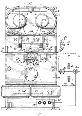
1844239 Power Transmission, H.O.
Boehme, E. Knopp, F. Kunc (H.O. Boehme Inc), Feb 9 1932,
476/48
; 476/51; 477/15; 477/19; 74/348; 74/745 - machind dwgs
1858511 Automatic Telegraph Keying Head, F. Kunc, E. Knopp (Boehme
Inc), May 17 1932,
178/17A ; 234/75 -
1939215
Photo-Electric Keying Head, F. Kunc (Boehme Inc), Dec 12, 1933,
178/17D
; 178/17R; 235/458 - works with paper tape where the holes are
seperated by less than a hole radius. (see Fig 1 above)
2006714
Tape Guide, F. Kunc (H.O. Boehme Inc), Jly 2 1935,
40/342
; 226/118.4; 226/196.1; 242/615.21 -
2672509
Teletypewriter Frequency Shift, J.H. McCoy (Army), Mar 16, 1954,
375/306
-
3440452 Timing Circuit, G.J. Boehm (ITT), Apr 22 1969,
327/276
; 327/392 -
Gill Selective Telegraph
There are three closely related product types. The lock
controlled by Morse code, the telegraph (or telephone) selective
calling system and a single railway visual signal controller.
Noticet the first 5 patents were issued on the same day.
430606
Magnetic Power Equalizer, W.W. Alexander (Gill-Alexander Electric
Mfg Co), Jun 24 1890,
430607
Electro Mechanical Combination Lock, W.W. Alexander
(Gill-Alexander Electric Mfg Co), Jun 24 1890,
430608
Electro Mechanical Combination Lock, W.W. Alexander
(Gill-Alexander Electric Mfg Co), Jun 24 1890,
430636
Electric-Circuit-Controlling Apparatus, E.R.
Gill (Gill-Alexander Electric Mfg Co), Jun 24 1890,
430637
Automatic Signal and Switch Controlling
Apparatus and Verfying Mechanism, E.R.
Gill (Gill-Alexander Electric Mfg Co), Jun 24 1890,
540620
Electric Circuit, W.W. Alexander (Gill-Alexander Electric Mfg Co),
Jun 11 1895,
548282
Electromechanical Lock, W.W. Alexander (Gill-Alexander Electric
Mfg Co), Oct 22 1895
557749
Automatic Electric Railway Signal, W.W. Alexander (Gill-Alexander
Electric Mfg Co), Apr 7 1896,
246/3 ; 246/123; 246/263 -
Known for Fire and Police alarm call boxes (Wiki)
and systems. Note that San Francisco (SF
Gate), Boston and New York still used call box systems
because they continue to work in cases where cell phones fail
(9/11).
Firefighters Hall &
Museum - Minneapolis -
The
Fire Alarm Telegraph System -
Video
Links
Tom Perera, W1TP:
How to
Build Simple Telegraph Sets -
uv201.com/Misc_Pages/telegraph_instruments.htm
Artifax Books -
Information
on Screw Threads - Whitworth
55 deg in 1860, American NC and NF in 1864
The Telegraph Museum - mostly
keys
Telegraph-History -
nice pages with key developments - Bunnell Telegraphic and
Electrical Co. Catalog
11 -
"Telegraph Lore" ! - Patents
- Telegraphic
Technology index page -
Telegraphic Instruments
of Europe by Fons Vanden Berghen his book Classics of communication is
out of print.
The Telegraph Office
-
Birthplace of the Telegraph - Telegraph
-
J.H. Bunnell & Company -
A Brief History of
the Morkrum Company - later became Teletype Co.
The Stock
Ticker Census - lists a number of different model numbers.
Stock Ticker Co.
Reproduction is like the 1875 model $35,000 each
Clauss Studios
Stock Ticker Parts Manuals Domes, Pedestals & non working full
size models
Thomas A. Edison
Papers - Chronology
-
Early Technology - Office
equipment - Telegraph
Instruments -
A Short History of Telegraphy -Part 1,
Beginnings - Part 2,
Making a Record - Part 3,
Start-stop to Date -
Telegraph
- The
Electromagnetic Telegraph - Teletypewriter
-
Paper
Tapes and Punched Cards - illustration of Wheatstones Morse
tape and 5 level TTY tape.
North American Data Communications
Museum -
Distant Writing
- A History of the Telegraph Companies in Britain between 1838 and
1868
Engines of Our
Ingenuity - transcripts of radio programs similar to the
Connection series on TV
Telegraph
Sounder clicks out RSS Feeds: - How to Almost build a sounder
- There should be an iron strap joining the bottom of the two
electromagnets. The cross section of each part of the magnetic
path should be about the same area. Also it's important to
wire the electromagnets so they aid, not buck.
Lords of Lightening - a
directory for telegraph researchers
Back to Brooke's Home, Military Information, Phones,
Telephone Patents, web pages
[an error occurred while processing this directive] page created 24 Jan
2007.