Stock tickers have been around since
the mid 1850s. It was work on stock tickers that got Thomas
A. Edison his start. Prior to inventions on stock tickers he
was broke. In a few years of work on stock tickers he
assigned his rights in many patents for about $40,000 ( 66 million
in 2007 dollars). This allowed Edison to setup his New
Jersey labs.
Stock tickers have been developed to meet the need at the
time. But whenever there's a stock market crash the ticker
system can not keep up. So after Black Friday, Sep 24, 1869
a new generation of tickers came on line based on the Edison
Universal. Ticker machines similar to the Universal (housed
in a glass dome), but faster were used through the market crash
October 29, 1929 where they could not keep up.
The Western Union (they had bought out virtually all the
independent telegraph and stock ticker companies by the start of
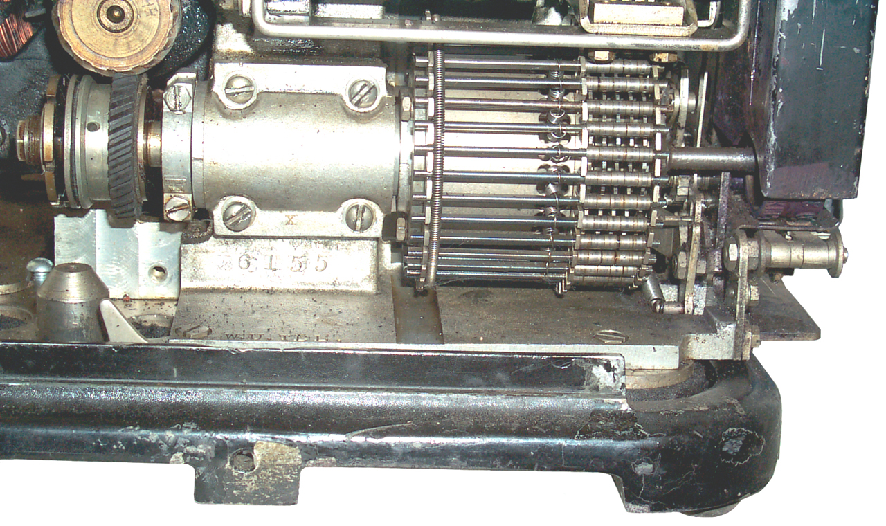
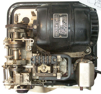
the 1900s) then came out with the Ticker 5-A. Although the
5-A prints on paper tape in a way to looks like the prior stock
tickers and the paper tape was used for "ticker tape" parades, it
does not use the step by step method of the prior tickers and so
probably should not be called a stock ticker machine, i.e. the 5-A
sounds different. The 5-A operates at 500 characters per
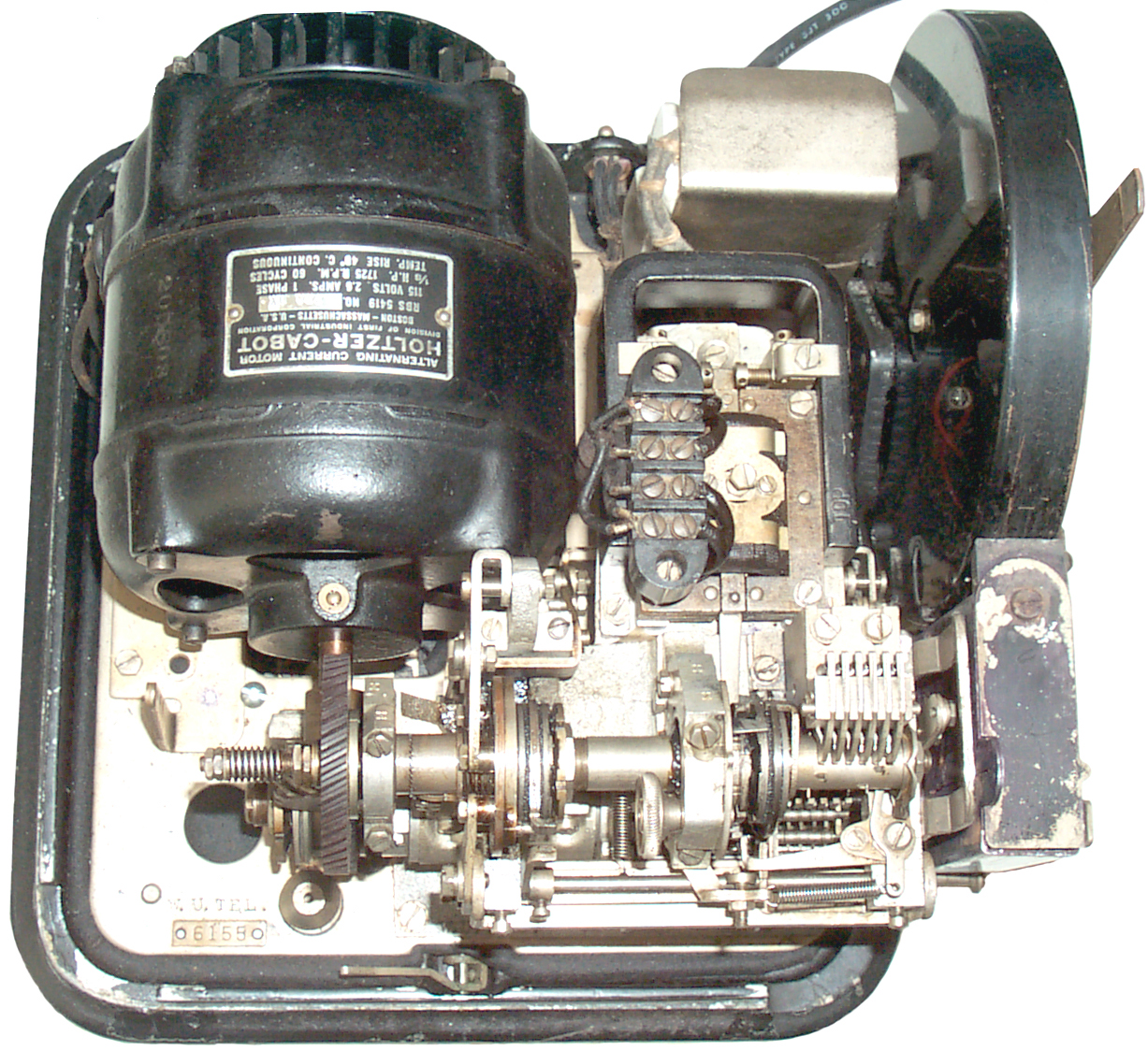
minute maybe 8 quotations each second. In Fig 1 you can see
that this particular one has louver vents, not drilled holes.
You could say that the Edison stock ticker was the father of the
5-A and the Model 26 teletype was the mother. The model 26
uses a "pineapple" selector that's very similar to the one used in
the 5-A although they are not interchangeable. The 5-A uses
a Unison device that's very similar to the one Edison invented and
was used on most if not all the Edison stock tickers. The
5-A runs at 500 C/M (83 W/M) compared to the 60 W/M for the
26. Some say that the model 26 is newer than the 5-A but the
first model 26 patent is dated 1926. Note it's common with
small arms to name them for the year of introduction. I
wonder if that's the case with Teletype machines with model
numbers like 15, 19, 26? The 5-A patents are for 1938.
The following is an excerpt from a Western Union news letter (I'm
trying to get the source info). It appears to have been
written prior to the roll out of the 5-A.
"This new ticker which will be
referred to by the name Ticker-5-A discards the step-by-step
principle on which the universal and self-winding tickers are
constructed. The ticker operates on a uniform code of 8
note 1 units per
character, using the start-stop principle after the manner of
all Simplex printing machines. One impulse of the code is
used as a start impulse and another as a stop or rest
impulse. Five units of the code are used for the selection
of the printing position on the type wheel and the sixth
selection unit is used to determine whether the character to be
printed is to be a letter or a figure. The 6 selection
units employ the same code as in use on the ticker automatics
system and on the C.N.D. channel note 2 printer system. The new Simplex
ticker will print on a tape with the same size note 3 and shape of
characters as on the present self-winding ticker. It
is a type wheel machine and the driving power and power for the
various functions such as printing, shifting from letters to
figures, and advancing the tape, are derived from a small
motor. The mechanism of the machine is very different from
any previous Simplex printer and is adapted to operate at a high
enough speed so that all of the line time possible on a single
wire may be used to operate the one machine. It is not,
therefore, necessary to channel note
4 the circuit on which these new tickers will operate.
It is difficult to present an adequate picture of the magnitude
of the work involved in making a conversion of . . missing
. .
will transmit _____ out to Other long distance circuits, and
others will work into thicker circuit panels for which, in turn
the tickers in the city will be operated. A Drawing
#34297 is included in this summary showing what the distribution
circuits will be after conversion to Tickers 5-A has been
completed.
The new ticker operates on one line wire and with a current of
from 50 to 100 milliamperes. It has only a single polar
line note 5 magnet.
The resistance note 6 and
inductance of the line magnet are considerably less than that of
the self-winding ticker so that a greater number of tickers of
the new type may be placed in series in one line. It is
expected that this ticker will handle satisfactorily, a day's
trading of between 7,000,000 and 8,000,000 note 7shares. If that
figure is reached and surpassed, the only logical step note 8 would be to duplicate
the ticker system and not attempt to design a ticker with a
greater output than the one which we are about to put into
service."
note 1 - The patents talk about a modification that would allow
the 5-A to work with regular start-stop teletype machines, but
that's not the way it was used for quotation service.
There is was used in the 5+1=6 bit isosynchronous mode.
note 2 -What is C.N.D.?
note 3 - 3/4" wide paper tape.
note 4 - multiplex
note 5 - electromagnet or polar relay
note 6 - 20 Ohms & 150 mh
note 7 - a quotation consists of the company symbol letters and
the price in numbers. The number of shares is not on the
tape. Most stocks are sold in blocks of a hundred
shares. The average trade is probably some hundreds of
shares, let's say 400. 8,000,000 shares would be 20,000
trades. If it takes 8 characters for each trade that's
160,000 characters, at 500 char/min that's 320 minutes or 5.3
hours. The market may have been open for 6 hours per day
so that's a reasonable estimate.
note 8 - Whoever wrote this article did not allow for a
completely new system, and in fact the electronic system that
replaced the 5-A has a capacity that's so much higher it's hard
to quantify.
Signaling Systems
Step by Step
The type wheel is stepped one character at a time very much like
the second hand in a quartz clock is stepped every second.
For example if you want to print BAC the type wheel needs to be
stepped from wherever it is to the B. Then it needs to be
rotated 1 position short of a full turn to print A then 2
positions to print C. Most type wheels have about 30
characters so step by step uses about 15 bits per character (half
the number of characters).
Unison
The other problem with the step by step method is there needs to
be a way to keep all the receiving printers in unison with the
transmitter. This problem plagued the step by step printers
and there's a U.S. patent class devoted to Unison Devices
(178/41).
T.A. Edison invented one of the first unison devices for his
Universal stock ticker. It uses a spiral groove on the
printing shaft with a pin riding in the groove. If the type
wheel made about 3 turns with the pin in the groove the type wheel
would lock up in a known position. So to get all the
machines in unison the sending station would send a long string of
pulses thus bringing all the machines into unison. This
could be done often, whenever there was a break. In normal
operation every time a character was printed the pin was lifted
out of the groove and brought back to the starting position.
Since in normal operation the type wheel is never turned more than
a single turn the machine would never be perturbed by the unison
device.
Teletype Machines
Permutation Coding
Teletype (the common (brand) name
for a
teleprinter)
machines
use
what's called permutation coding of the characters. This
means that unlike the stock ticker machine where you just rotate
the type wheel one character for each pulse on the line the
Teletype receiving machine needs to remember the order of the
signals that make up one character. Budot used a 5 level
binary number system to choose one of 32 characters which is
about 3 times more efficient than the step by step method.
Stop/Start Idle/Printing
On/Off Mark/Space
Teletype machines also use what's
called
asynchronous
which means that the timing of each character does not need to
be related to a common clock or other characters. This is
accomplished using two states of the line: key up no signal
(open circuit) or key down, signal being sent (current flowing).
An advantage of On Off Keying (OOK) is that when the key
is up little or no power is being used making it more economical
than Bi Polar keying.
When the line is idle a current flows that locks the selector so
that it does not turn (stop condition). As soon as the
current is broken (start bit) the selector starts rotating and
as it makes one turn the incoming data bits setup the character
that's to be printed. After the last data bit (5 data bits
on early systems and 8 data bits on later systems) the character
is printed. The last bit of each character is always the
current flowing condition which stops the selector. The
stop for mechanical printers was commonly 1.5 or 2 bits long so
that you were sure that the selector stopped. So to send a
character takes 1 start bit + 5 data bits + 2 stop bits or 8 bit
times per character (1 of 32).
If a Teletype machine is powered but there is no line current
(like if the line breaks) then the selector mechanism is
released that the machine makes a lot of noise as it receives
what's commonly called a rubout character.
For either 5 or 8 level machines during a message a large
percentage of the character time is spent in the start and stop
states.
Todays computers use this asynchronous method for the serial
(COM) ports. But today there's no mechanical inertia
problem so only 1 stop bit is used. A common serial
description is 8N1 meaning 8 data bits, No parity and 1 stop
bit.
Letters Figures Shift
The 5 level system used a Figures
Letters shift in order to be able to print all 26 upper case
letters and also the digits and a small number of punctuation
marks (no lower case letters). This system has a problem
if a shift is not properly received, then what should have been
letters is what appears to be random punctuation marks and
carriage returns and line feeds in strange places or the
opposite problem where what should be numbers is printed as
letters. A good operator can recognize the problem and
press the needed shift key or later manually annotate the
message with the correct characters, but it's added work.
The 8 level system eliminated the Letters Figures shift problems
and supported the ASCII character set that includes both upper
and lower case letters and a host of features.
Western Union 5-A
Much of the development work on
Teletype machines was done prior to the stock market crash of
1929 so when the 5-A was designed the operation of Teletype
machines was well known at Western Union since they developed
them. The 5-A includes many improvements on the Start Stop
Teletype.
Permutation Coding
The 5-A uses a 6 bit permutation
code. The 5 bits are not probably the standard ITA 5 level Baudot
code used with regular teleprinters and the 6th bit is used for
Numbers or Letters shifting. This way there are no
separate characters (keys) for Shift to Letters and Shift
to Numbers. So the locked in the wrong shift problem goes
away.
Bi Polar Signaling
Early on in telegraph history it
was discovered that on long circuits when the key was up there
was likely to be false signaling because of coupling from other
telegraph lines. There are ways around this problem.
One is to keep a small current always flowing (place a rheostat
across the key terminals) and that tends to lower the
noise. A much better way is to use bipolar
signaling. This can be done by using a key with a common
terminal, a normally open terminal and a normally closed
terminal. With the key up a battery with it's positive
terminal connected to the N.C. terminal feeds the line and when
the key is down the the N.O. terminal feeds the line from the
negative terminal of another battery. Thus there is always
a current flowing. Bi polar operation was commonly done by
using special relays at both the sending end and receiving end
of long lines. At the receiving end the Bi polar relay
output would be the OOK signal to the Teletype machine in a
local loop.
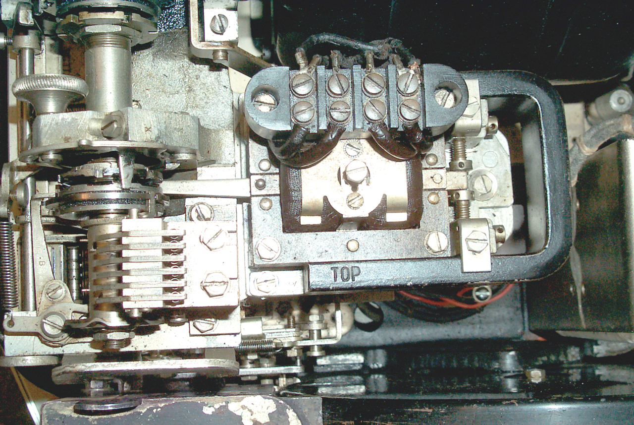
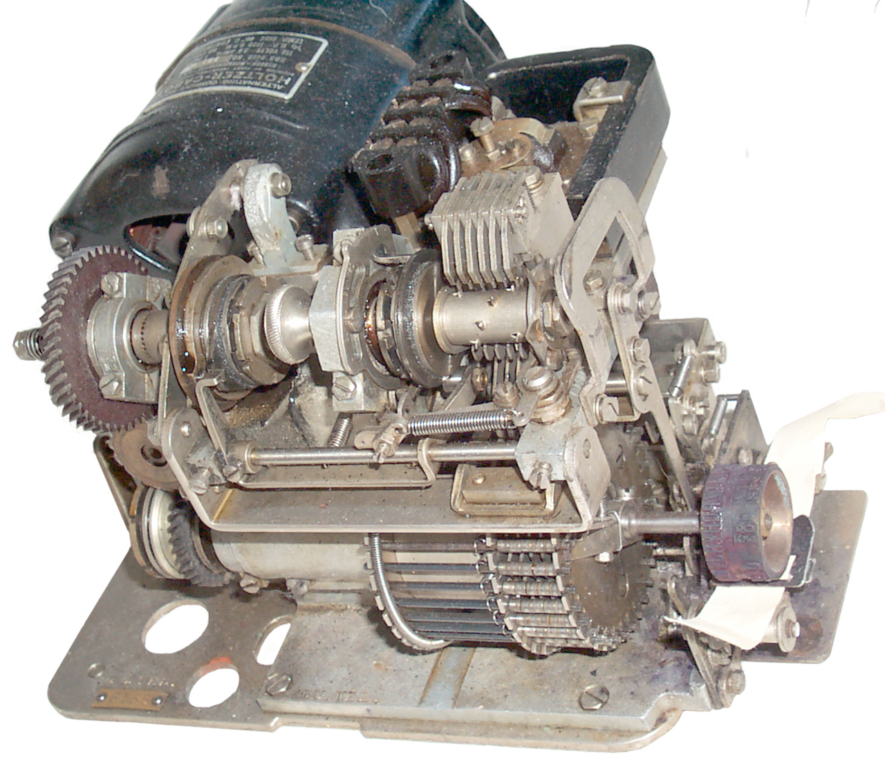
Instead of using OOK the 5-A has
a built-in polarized electromagnet that responds to polarity
reversals. In Fig 6 above you can see a "U" shaped magnet
marked on one end "TOP" that surrounds the electromagnet
changing it from a common type that actuates with either
polarity to one where the direction of actuation depends on the
polarity of the input current.
Coil Data
12 Apr 2007 - The Polar Relay has a resistance of 20 Ohms.
The nice thing about it is that when 1.1 Volts is applied in
either polarity the relay actuates. This was surprising
since Teletype machines typically work with loop voltages of 80
to 160 and currents of 20 or 60 ma.
In order to drive the Polar Relay using a PIC micro controller I
think a simple 3-terminal linear voltage regulator connected as
a current source of maybe 80 ma from a 5 volt supply. An H
Bridge will supply the polarity reversal and in addition give
the option of either an open circuit between reversals or a
short (they call it motor braking) between reversals.
Modern cameras use an H Bridge controller for focus that is both
small and has the needed specs.
17 Apr 2007 - the Polar relay has an inductance of 150 mH.
You would like the rise time to be less than 1% of the bit time
so the bits have good fidelity. A bit time is 20 ms and 1%
of that is 200 uS.
For a single time constant rise time it takes 3 to 5 time
constants to get to almost 100% so the needed time constant is
about 40 us.
The needed R = L / 40 us = 3750 Ohms or 3730 Ohms resistor + 20
ohms in the coil. To get 100 ma through 3750 ohms says the
loop voltage needs to be 187 to 375 volts. But that's if
using a voltage source. The actual voltage across the coil
in a steady state condition would be 375 V * 20 /3750 = 2
volts. At the instant the loop is closed the current
in the coil will be zero and will exponentially rise with the
time constant L/R, so in 200 us (5 time constants) will be
very close to steady state, i.e. very close to 2 volts.
So instead of using a
high voltage powers supply and a big series resistor why not
just use a 5 volt power supply and a current source?
This is not the way teletype machines are normally driven so
maybe there's something I'm missing.
18 Apr 2007 - On the
Greenkeys
mailing
list I learned how to figure out the answer. The
problem occurs when the circuit is opened and the coil contains
energy that needs to be dumped as fast as possible. If a
diode or Transil is placed across the coil then the time
constant is long (R is low t.c. = L/R). So you want to
operate the coil in as high a voltage circuit as needed to get
the desired off time. The needed voltage is given
as:
V = L * dI /dT which in the case of an older RTTY machine
running at 100 baud with 10% distortion might be V = 4 H * 60 ma
/ 1 ms = 240 Volts. But for the 5-A running at 50 baud it
works out to V = 150 mH * 60 ma / 2 ms = 4.5 Volts. If a
higher voltage is used the off time gets shorter.
The loop is still
best implemented as a current source to keep the loop
resistance as high as possible for the turn on condition.
A
current source becomes a low resistance if it's saturated.
For example an analog current source set for 100 ma from a
voltage source of 20 volts is trying to drive a coil that at
t=0- has no current. At t=0+ the coil current is zero and
the current source can only become a short to try and supply the
needed 100 ma. Once the actual coil current gets near 100
ma then the current source starts backing off and then looks
like a high impedance. But during the critical transition
time it was a low impedance that slowed down the turn on time
constant to Lcoil / Rcoil, which in this case is 150 mH / 20 Ohm
or 7.5 ms, way too slow.
Loop Voltage
|
R
100 ma
|
TC
ms
|
5*TC
|
200
|
2k
|
.075
|
0.37
|
100
|
1k
|
0.15
|
0.75
|
75
|
750
|
0.2
|
1.00
|
50
|
500
|
0.30
|
1.50
too slow
|
With a loop voltage of 75 and a 750 Ohm resistor the coil
charging time constant will be 0.2 ms for (5 * tc) turn on time
of 1 ms.
75 v * .1 amp = 7.5 watts which since this is a bi polar system
is on all the time.
25 May 2007 - I've found a couple of ways of driving the
selector electromagnet.
Full H-Bridge - This
uses two half bridges where a half bridge consists of two
electrical switches stacked one on top of the other. The
top switch is connected to the 80 volt power supply and the
bottom switch to ground. The common point of the switch is
connected to one of the selector electromagnet inputs.
Another half bridge is connected to the other input. Now
when the left half bridge has the top switch on and the bottom
switch off and the right bridge has the bottom switch on and the
top switch off the polarity is in one direction. When all
the switches are flipped the polarity is flipped. The
forbidden condition is that you do NOT want the top and bottom
switches in a half bridge both on at the same time since this
would short the power supply to ground. When N channel
MOSFETs are uses as the switching elements the gate bias for the
top switch needs to be higher in voltage than the source of the
device, i.e, it needs to be higher than the HV power supply
voltage. IR and others make half bridge drive ICs that
have a small switching power supply to do this and in addition
have circuitry to prevent the shoot through that can short out
the power supply.
2T2R - I made up the
name for Two Transistors and Two Resistors almost full
bridge. Here the two bottom switches are MJE340 high
voltage power NPN transistors but the two top switches have been
replaced with power resistors one of which sets the loop
current. See
RTTY
the
Easy Way (BARTG). When a transistor is turned on
that line wire is at ground. When a transistor is turned
off that line wire goes through the resistor to the HV power
supply. But notice that for the transistor that's turned
on the resistor above it has the full power supply voltage
across the resistor. So this circuit requires a
transformer (
Triad
N-68x) that can deliver a little more than twice the loop
current.
Good information about the HV supply is on the
TTY Connect
Teletype Interface System web page, but unfortunately this
is a Neutral or On Off Keying type of interface that's common in
the U.S. the RTTY the easy Way design is from Britain where
polar drive is the standard.
Unison
The 5-A does NOT use
a start and stop pulse. (the first patent below
says this, but I've heard the 5-A tickers are run using the option
in the second patent with start and stop pulses) Every line
polarity change is considered a clock edge. Thus the 5-A can
operate like a synchronous data protocol saving the time needed
for the start and stop bits. One of the patents calls it
"self synchronous". But the 5-A is not what's today called a
synchronous system since it can stop, pause and restart at any
time between characters. Since there are no start or stop
bits it's easy to combine signals using a multiplexer so that they
all can be sent on one channel.
The unison device is very much like the Edison unison. It
consists of a worm gear on a shaft with a pin riding the
groove. If for example the machine is plugged in and turned
on with no connection to the bi polar magnet the the pin will
continue moving the the groove and after a few turns will lock up
the selector. At this point the motor is turning but the
selector mechanism is quiet. The preferred method of
obtaining unison is to supply marking current polarity to the line
when no characters are being sent for maybe 5 character times thus
bringing the machine into unison. Then when character bits
are sent the 5A keeps in unison.
The second patent mentions that it's desirable to not stop sending
thus allowing the unison device to activate, but better to keep
the line active with data so that the cams stay
synchronized. How that's done without printing anything is
not specified. There are no non printing characters on
the type wheel that could be used. You wold not want to
print a blank character because that would feed the paper
tape. What's needed is to have the line current reverse in
such a way that the printer keeps in sync yet does not trigger
printing. Maybe flipping the polarity once every word time, i.e.
once every 300 ms? Not an issue since the 5-A does use the start
stop method.
Pipe lined Printing
The Teletype machine has the time from the last data bit plus the
stop bit(s) plus the start bit to complete printing a
character. But the 5-A has no stop or start bits and so
would have difficulty printing characters at a rate of 500 per
minute if it all had to be done in less than a bit time.
This problem is solved by printing the character during the
incoming bits of the following character. This way there's
about 5.5 (110 ms) bit times available to print the character
before the next character needs to get latched.
It turns out that the 5-A knows the type wheel position after 5
bits. The sixth bit either chooses column 1 or column 1 on
the type wheel by shifting the wheel or not shifting. The
sixth bit can therefore be used as a signal to transfer the 5 bits
from the input selector bars to the memory bars thus pipelining
the character. Now the input selector bars are ready to read
the next input character and the type wheel has a full character
time to move to the next position.
Timing
A comparable teletype machine would use the same bit time of 20
ms. The computation goes like this:
20 ms per data or start bit and 28.4 ms for a stop bit so a
character length is 20 ms + (5 * 20 ms) + 28.4 ms = 148.4 ms /
character or 6.7 characters per second, which times 60 seconds in
a minute is 404.3 characters per minute. In Morse code when
looking at timing the 6 letter word PARIS is used. So to get
from characters per minute to words per minute we divide 404.3 by
6 which comes out 67 WPM called 66 WPM.
For the 5-A using the same bit time of 20 ms * 6 data
bits = 120 ms / character or 8.33 characters per second times 60
is "500 Characters per Minute" and is the number often mentioned
about the speed of the 5-A. Dividing the CPM by 6 characters
(letters) per word gives 83 Words per Minute. But the 5-A is
not run in the isosyncrhonous mode.
I'm not sure if my 5-A has the optional parts to make it into a
start stop machine as is described in patent 2135375 or if it's an
isosynchronous type like in patent 2117241. 18 Apr 2007 -
It's looking more and more like this machine, and most of the 5-A
machines, were configured for start stop operation and used the
USTTY aka ITA2 alphabet for letters, but the figures may be
unique? There are a number of different type wheels that can
be used on the 5-A. The one called financial or business has
all the fractions in 1/8 steps to do stock ticker work.
There are other versions for weather that have the circles with
different patterns inside to represent different cloud types,
there is also a wheel for sports reporting.
Line Connection
The cable to the line has three wires:
White - ???
Red and Black to polar coil.
The Bi Polar relay appears to be 20 Ohms resistance. Red to
Black is 20 Ohms, but none of the wires connects to the chassis.
The second patent shows a circuit (2135375 Fig 22) that describes
how the output of a 6 level tape reader can be fed through some
relays and a rotating selector to drive a single wire with a bi
polar signal.
Type Wheel
It's very important that the type wheel print the letters at the
top of the tape and the numbers at the bottom. This is to
allow quick eye scanning of a tape to separate or find a stock
symbol. Later machines tried to use two different colors of
ink and print in a straight line, but the separation works the
best. Today the electronic scrolling stock ticker displays
still use the offset letters and numbers for the same reason.
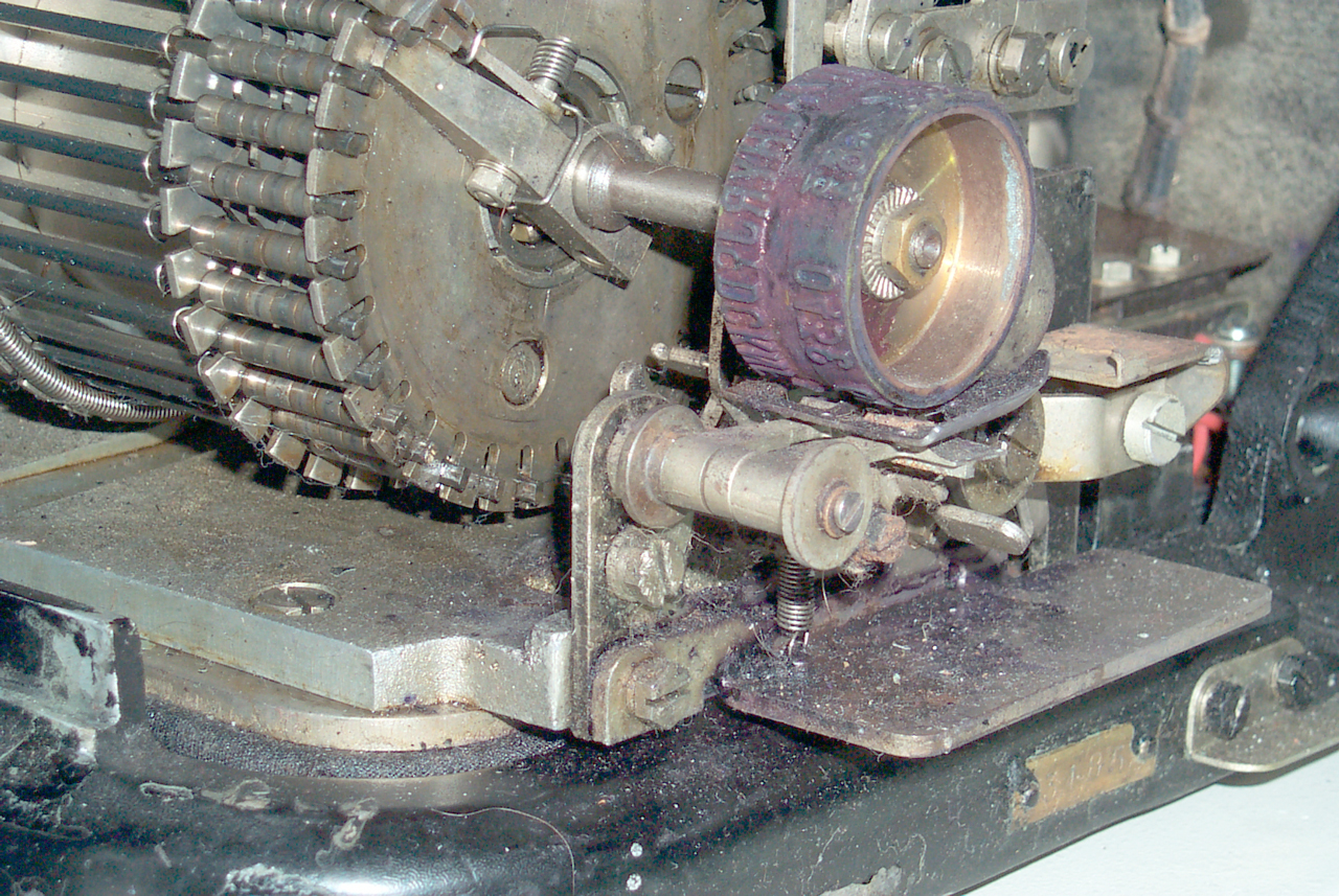
After the combined paper tape canister and ink roller box is
removed (take out three screws) you can see the type wheel.
The type wheel is connected to the selector cage "pineapple" which
determines where the type wheel will be when it's time to print a
character. The selector cage has a notch in it that takes up
2 of the 34 index positions that are possible so only 32 index
positions are used and 2 are always skipped.

|
|
Type
wheel photo 1
|
Type
wheel photo 2
|
The type wheel is a smooth surfaced aluminum turning that has a
rubber strip of characters attached to it's circumference.
On either side of the of seam are the characters "." in both the
letters top row and the figures bottom row. I'm guessing
that the characters on either side of the seam fall into the notch
on the selector drum and so are never printed. That leaves
32 rotational positions that can be used times a letters or
figures shift for a total of 64 possible characters. They
are arranged in a strange way as follows:
the top row is numbered 0 to 31
the second row is numbered 31 to 0
the third row are the "letters" characters
the forth row are the "figures" characters
s
e
|
0
0
|
0
1
|
0
2
|
0
3
|
0
4
|
0
5
|
0
6
|
0
7
|
0
8
|
0
9
|
1
0
|
1
1
|
1
2
|
1
3
|
1
4
|
1
5
|
1
6
|
1
7
|
1
8
|
1
9
|
2
0
|
2
1
|
2
2
|
2
3
|
2
4
|
2
5
|
2
6
|
2
7
|
2
8
|
2
9
|
3
0
|
3
1
|
s
e
|
a
m
|
3
1
|
3
0
|
2
9
|
2
8
|
2
7
|
2
6
|
2
5
|
2
4
|
2
3
|
2
2
|
2
1
|
2
0
|
1
9
|
1
8
|
1
7
|
1
6
|
1
5
|
1
4
|
1
3
|
1
2
|
1
1
|
1
0
|
0
9
|
0
8
|
0
7
|
0
6
|
0
5
|
0
4
|
0
3
|
0
2
|
0
1
|
0
0
|
a
m
|
.
|
S
|
n1
|
U
|
I
|
E
|
.
|
A
|
.
|
F
|
N
|
K
|
C
|
D
|
n2
|
J
|
R
|
Y
|
H
|
Q
|
P
|
Z
|
T
|
W
|
L
|
X
|
M
|
.
|
V
|
B
|
O
|
&
|
G
|
.
|
.
|
s
|
.
|
1
4
|
9
|
5
|
.
|
1
|
c
|
6
|
_
|
n
3
|
3
|
4
|
0
|
_
|
_
|
3
4
|
8
|
*
|
_
|
7
8
|
1
8
|
1
2
|
_
|
5
8
|
$
|
_
|
3
8
|
2
|
-
|
B
|
7
|
.
|
Notes: I have numbered both ways so that when I'm trying to
figure out the coding one of them should be correct.
WRONG - Baudot was a hand
entry code so is not in binary order.
n1 is a symbol that looks like a capital letter "P" with a small
letter "r" underneath.
n2 is a symbol that looks like a letter "c" sitting on top of a
vertical stroke "|". (cents?)
n3 is a symbol that looks like an upside-down "5". (English Pound
Sterling?)
Rearranging in alphabetical order gives:
A
|
B
|
C
|
D
|
E
|
F
|
G
|
H
|
I
|
J
|
K
|
L
|
M
|
N
|
O
|
P
|
Q
|
R
|
S
|
T
|
U
|
V
|
W
|
X
|
Y
|
Z
|
1 |
2 |
3
|
4
|
5
|
6
|
7
|
8
|
9
|
_
|
N
3
|
_
|
$
|
_
|
-
|
7
8
|
*
|
3
4
|
s
|
1
8
|
1
4
|
3
8
|
1
2
|
5
8
|
3
4
|
7
8
|
The first 5 bits of the code for a vertical pair in either table
above will be the same. This does not match any of the TTY
codes where Figures 1 is paired with letter Q.
That's because it's
ITA2. This code was developed by Baudot for input
using two
fingers of
the left hand and three fingers of the right hand and so the
letters are NOT in binary order.
5-bit ITA2 Code with most significant bit on the left
The bottom row is the "figure" that's paired with the Letter row
on the 5A.
ITA2
|
0
|
1
|
2
|
3
|
4
|
5
|
6
|
7
|
8
|
9
|
1
0
|
1
1
|
1
2
|
1
3
|
1
4
|
1
5
|
1
6
|
1
7
|
1
8
|
1
9
|
2
0
|
2
1
|
2
2
|
2
3
|
2
4
|
2
5
|
2
6
|
2
7
|
2
8
|
2
9
|
3
0
|
3
1
|
Let
|
Nul
|
E
|
LF
|
A
|
Sp
|
S
|
I
n1
|
U
|
CR
|
D
|
R
n2
|
J
|
N
|
F
|
C
|
K
|
T
|
Z
|
L
|
W
|
H
|
Y
|
P
|
Q
|
O
|
B
|
G
|
STF
|
M
|
X
|
V
|
|
Num
|
Nul
|
3
|
LF
|
-
|
Sp
|
Bel
|
8
|
7
|
CR
|
WRU?
|
4
|
'
|
.
|
|
|
:
|
(
|
5
|
"
|
)
|
2
|
#
|
6
|
0
|
1
|
9
|
?
|
&
|
|
.
|
/
|
;
|
STL
|
5Afig
|
|
5
|
|
1
|
|
s
|
9
|
1/4
|
|
4
|
_
|
_
|
_
|
6
|
3
|
n3
|
1/8
|
7/8
|
|
1/2
|
8
|
3/4
|
_
|
* |
_
|
2
|
7
|
|
|
5/8
|
3/8
|
|
The 5A uses a 6 level code and so has 64 possible characters and
does not make use of neither Shift To Letters (STL) nor Shift To
Figures (STF).
The special symbols n1 and n2 appear in the Letters row. So
it looks like the 5A code has little if any relation to the ITA2
code.
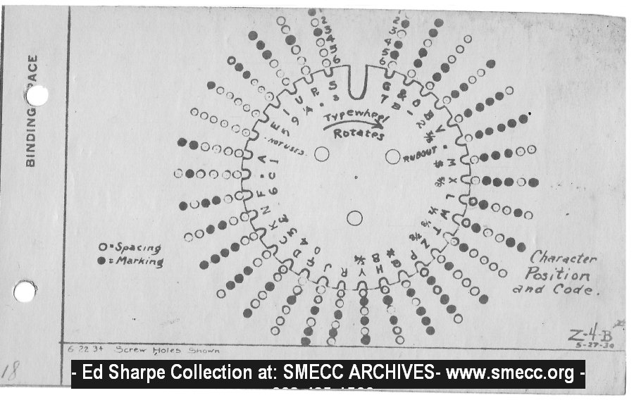
Selector Lever Code and Order of Characters on the Typewheel
of High Speed Ticker 3-2-29
Image from SMECC.org
Note that the levere code chart only shows a table of 32
characters (5 bits), but the 32 character sample tape
shows the relationship between the letters and figures. An
actual tape can not show both the letters and figures characters
at the same time, but this composite shows the relationship
between the two. What is the order of the sample tape?
Notice that the first column has one marking (shaded) bit, the
next column 2 marking bits, the 3 & 4 marking bits all
together, then various arrangements of the marking bits where
there's a spacing bit between them. Why that
arrangement? Let me know.

Type Wheel Position & Code diagram
Image from SMECC.org
Starting with Notch
bit order 1 to 6
Code
|
Let
|
Fig
|
101000
|
S
|
s
|
001000
|
R
|
.
|
111000
|
U
|
A
|
011000
|
I
|
9
|
100000
|
E
|
5
|
000000
|
na
|
na
|
110000
|
A
|
1
|
010000
|
.
|
c
|
101100
|
F
|
6
|
001100
|
N
|
_
|
111100
|
K
|
n3 |
011100
|
C
|
3
|
100100
|
D
|
4
|
000100
|
n2
|
0
|
110100
|
J
|
|
010100
|
Y
|
3/4
|
001010
|
H
|
8
|
111010
|
Q
|
*
|
011010
|
P
|
|
100010
|
Z
|
7/8
|
000010
|
T
|
1/8
|
110010
|
W
|
1/2
|
010010
|
L
|
|
101110
|
X
|
5/8
|
001110
|
M
|
$
|
111110
|
.
|
RO
|
011110
|
V
|
3/8
|
100110
|
B
|
2
|
000110
|
O
|
-
|
110110
|
&
|
B
|
010110
|
G
|
7
|
Notch
|
|
|
na not applicable
n1 is a symbol that looks like a capital letter "P" with a small
letter "r" underneath.
n2 is a symbol that looks like a letter "c" sitting on top of a
vertical stroke "|". (cents?)
n3 is a symbol that looks like an upside-down "5". (English
Pound Sterling?)
RO Rub Out (not all holes on tape because the sixth level is not
a hole)
Ticker Paper Tape
Probably: 3/4" wide suitable for printing (not oiled like
for punching). Max outside diameter for a new spool
7". Core center hole about 7/16". Paper tape is
available from
Claus Studios
he uses a band saw to cut a slice off a longer roll.
Patents
| Patent
1821110 |
|

|
WU 5-A
1821110 (pdf) Selecting and Printing
Mechanism, Sterline Morton, Howard L. Krum, Edward E. Kleinschmidt
(Teletype), Sep 1 1931,
178/33R ; 101/93.19; 235/429
This patent looks like a much
better fit than 2117241 & 2135375 and is much earlier.
Has two selector mechanisms, the first is set by the code and
the second is set by the first. This way a character can
be printing while the next character is being decoded.
1884754 (pdf) Printing Telegraph, H.L. Krum (Teletype), Oct 25
1932,
178/28 ; 400/186; 400/257; 400/62 - stock or news
broad printer - moving type wheel
has a strong similarity to the 5A
stock tape printer
2117241
Telegraph Printer, R.F. Dirkes, E.R. Wheeler, V.R. Kemball
(WU), May 10, 1938 178/34 ; 178/38 (18 pages)
This is not a step-by-step printer
but instead a Start-6 unit bi-polar code-Stop type printer.
Since stock quotes are almost continuous instead of actually start
- stop type operation this printer can keep running and only
correct the speed as needed. Eliminating all the stop-start
cycles makes operation quieter and is easier on the mechanical
parts.
A type wheel is used in the 5A that similar to the type wheel used
in the prior stock tickers and not a drum like in the Teletype
machine. But instead of pulsing the type wheel one step at a
time it's spun by a motor until it hits a stop that selects which
character gets printed.
Although this patent is for a tape printer many of the features
are specified for either a tape or page printer.
178/34 = Telegraph - Printing - Page - With Type Wheel Recorder
178/38 = Telegraph - Printing - Page - With Type Wheel Recorder -
with Type Wheel
2135375
Telegraph Printer, V.R. Kimball, R.F. Dirkes, E.R. Wheeler,
(WU), Nov 1, 1938, 178/34 ; 178/38; 370/305
Included in this patent are a couple
of alternate cams that can be used so that this printer will
properly respond to start stop type telegraph signals, although
that would mean running a a slower speed. Also that instead
of letting the unison device activate by not sending anything for
a few character times it's preferable to keep the line active to
keep the cams turning.
178/34 = Telegraph - Printing - Page - With Type Wheel Recorder
178/38 = Telegraph - Printing - Page - With Type Wheel Recorder -
with Type Wheel
370/305 = Multiplex Communications - Low Speed Asynchronous Data
System (e.g., Teletypewriter Service) - Synchronizer - Start-Stop
Model 26
1595472
Telegraph Apparatus, H.L. Krum (Morkrum), August 10, 1926, 178/27
1632297
Printing Telegraphy, E.E. Klindschmidt (Morkrum), June 14, 1927,
178/17B ; 199/18
1635129
Telegraph Transmitter, C.L. Krum (Morkrum), July 5, 1927, 178/33R
; 400/478; 400/479
D112119
Printing Telegraph Apparatus Cover, G.R. Lum (Bell Telephone &
Teletype), November 8, 1938, D14/472 ; D18/12
1766713
Transmitter, E.E. Klindschmidt (Teletype), June 24, 1930, 178/27
2180360
Printing Telegraph Apparatus, H.L. Krum (Teletype) , November 21,
1939, 400/141.1 ; 400/156.1; 400/164.2; 400/164.4; 400/70
2193970
Printing Telegraph Apparatus, H.L. Krum (Teletype), March 19,
1940, 400/141.1 ; 400/70
2224546
Printing Telegraph Apparatus, H. Lottermann (Teletype), December
10, 1940, 400/142 ; 400/175
2230463
Printing Telegraph Apparatus, C.A. Levin (Teletype), February 4,
1941, 178/27
2247408
Printing Telegraph Apparatus, A.H. Reiber (Teletype), July 1,
1941, 178/29
2250012
Web Guide, W.H. Eddy (Teletype), July 22, 1941, 400/615 ; 226/23
Ticket Printer
2309688
Ticket printer, Walter
J Zenner, Teletype
Corp, App: 1941-03-08, Pub: 1943-02-02, - general purpose
for accounting?
Can be used in conjunction with:
2502837
Position indicating system, Ferdinand
S Entz, George
A Pullis, George
R Stibitz, Bell Labs, App: 1943-11-24, TOP SECRET, Pub:
1950-04-04, - What was this used for? Let me know.
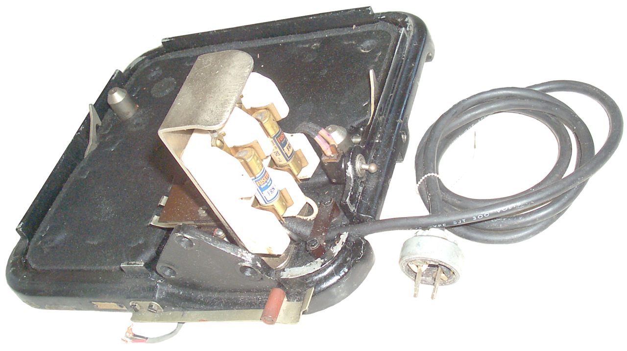
Loop Supply
Label:
TELETYPE
Input A.C. Volts: 115, Cycles: 50-60, Watts: 35
Rectifier: REC 45
Output D.C. Volts: 120/75 Amps. Cont: 0.2, Amps Int: (blank)
Supplied by
TELETYPE CORPORATION
Chicago, Illinois, U.S.A.
Manufactured by
North Electric Co., Galion, Ohio, U.S.A.

|
This has REC 45 fitted, not
the REC43 2 terminal socket.
|
|
Uses a strange AC 2 prong
plug.
The DC output is on a 3 socket cable.
Dwg No. WG-1606-8
|
TM-2215 Teletypewriters TT-5/FG and
TT-6/FG (Teletype Model 15 Maintenance) June 1951, 423 pages has
information on the power supply and on the
255A polar relays.
Links