Self Winding Clock Co.
© Brooke Clarke, 2007 - 2023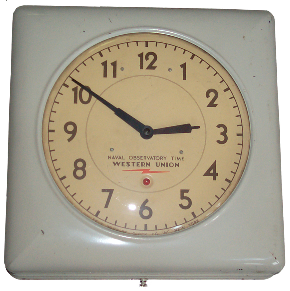 Fig 1 Fig 1 |
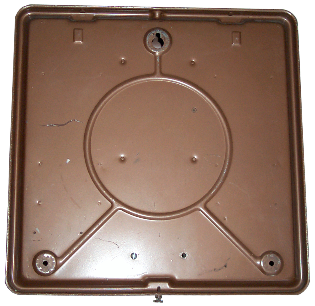 Fig 2 Fig 2 |
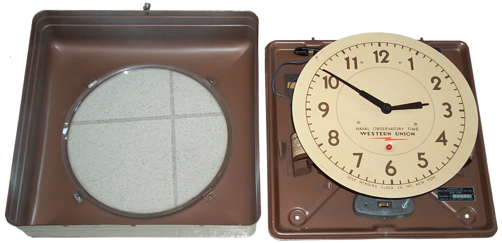 Fig 3 Fig 3 |
|
 Fig
4 Fig
4
|
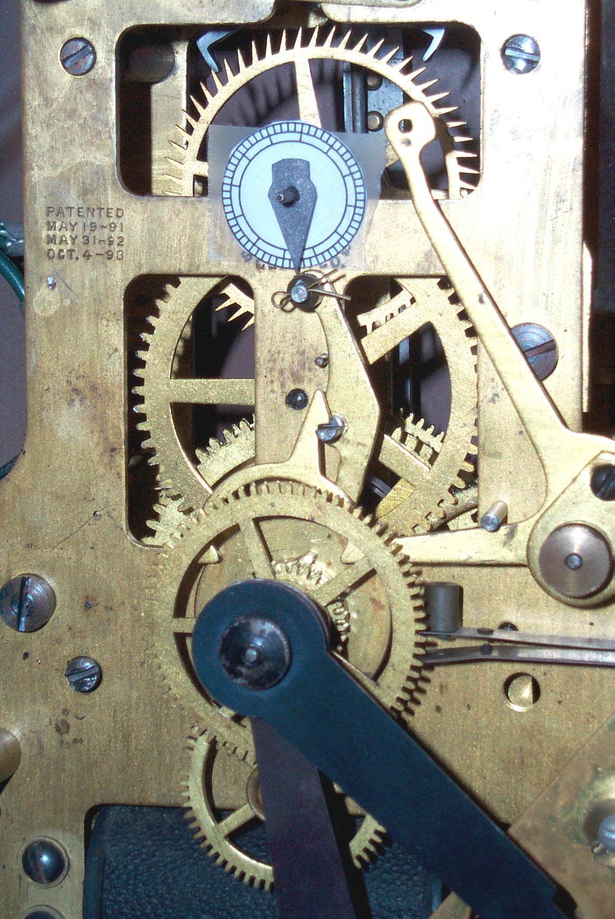 Fig 5 Fig 5 |
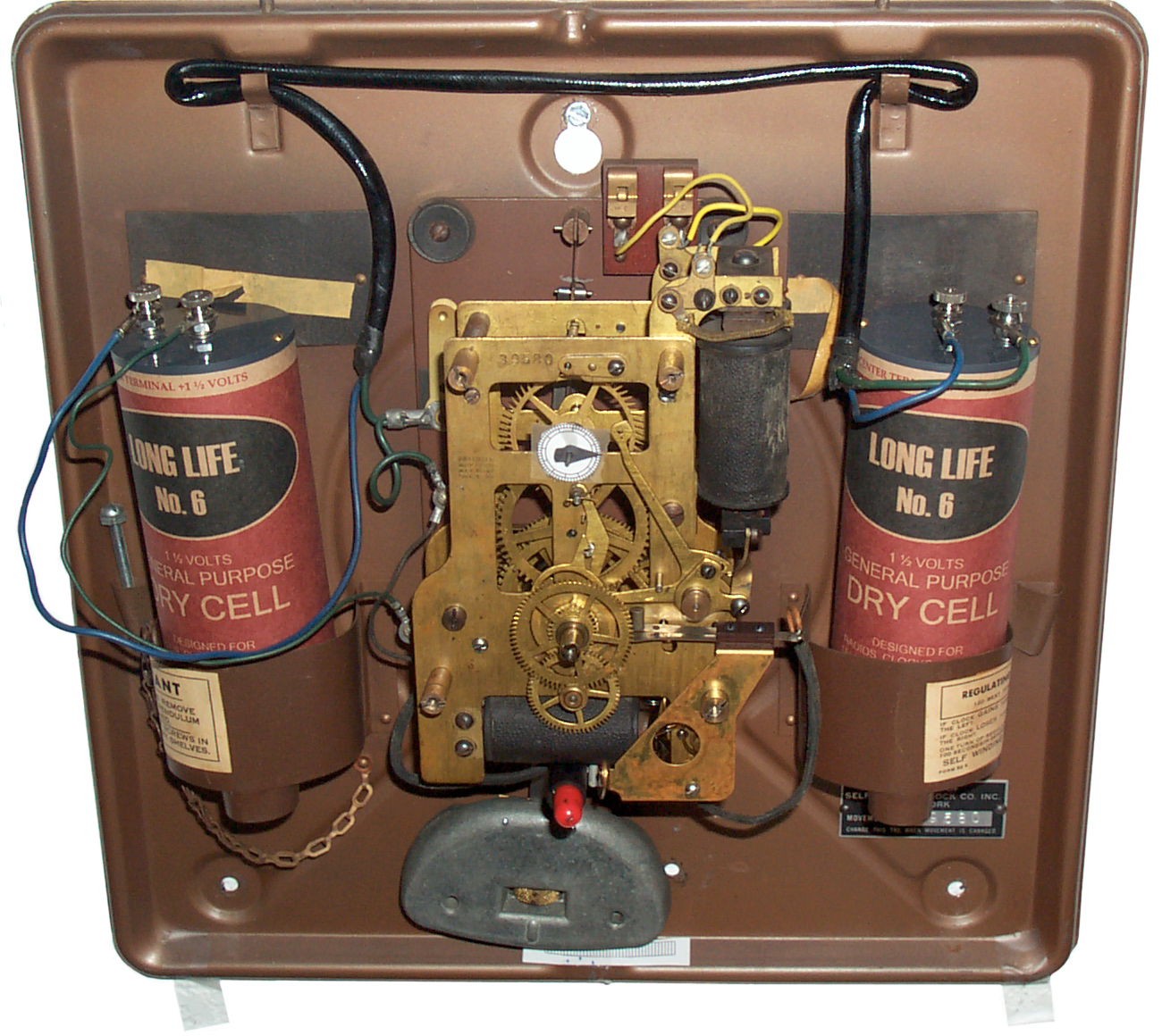 Fig 6 Fig 6 |
|
Opening
Operating
Dial
Movement
Escapement
Electrical
Winding Coils
Synchronizing Coils
Experiments Feb 2014
DC Power
Do NOT do this
New Winding Motor Contacts
Problem with Winding Motor Coil Insulating Washeres Rubbing on Rollers
Hourly Wind Switch
Syncronizing Problem with 19" Clock
How Stiff do the Batteries Need to Be?
Clock Stopped
Self Winding
Pendulum
Calculations
Barometric Compensation
Temperature Compensation
Synchronizing
Lubrication
Adjusting Rate
Mounting
Set the Beat
Set the Time
Adjust the Bob
Patents
Books
Product Ideas
YouTube
Links
Background
The earliest clocks used mechanical methods to power the movement. Weights that need to be periodically lifted or a spring that needs winding. If you forgot to wind a clock it would stop. This is as true today as is was then. So a clock that winds itself would sure be convenient.
The first figures show the clock as it arrived. Although there are some minor scratches on the outside paint the rest looks very good. The movement number is 39580. Marybeth Grisham has told me that the movement was made around 1900 - 1910 and later taken out of storage after 1938 when the red synchronizing light came out to make a clock. The synchronizer was available back in the 1900 time era, it's just the red bulb that was added in 1938. The white outer paint was commonly used in hospitals. The metal bob was designed to provide both temperature and atmosphere pressure compensation. The best clock of this type she has seen lost 15 seconds after 70 of running (without synchronization).
These clocks are still (2007) in use for the London underground and/or transportation locations.
Around 1932, 1933 the Self Winding Clock Co was about to go bankrupt and Western Union bought them and started making the Western Union clocks based on the "F" movement that had been in production for at least 24 years prior to that. So the movement 39580 was made long before the Western Union involvement.
The USNO started using the Photographic Zenith Tube about 1934 (article in Popular Astronomy Feb 1942).
If either batteries or mains derived DC power is used for the winding, if either fails for up to an hour or more, the clock just keeps on ticking powered by the internal spring. So, unlike most clocks, is very tolerant of power failures.
List of S.W.C.C. "Western Union" clocks
| # |
Case |
C # |
Mvement |
M # |
Comment |
| 1 |
15"
Square white |
39580 |
F -
dual sync coil |
39580 | reconditioned |
| 2 |
19"
Round 37SS |
402449 | F -
single sync coil + Relay |
402449 102898 |
missing
parts replacement movement |
| 3 |
19"
Square |
79008 |
F -
single sync coil |
42967 |
contacts
burned
by 6 V |
| 4 |
19"
Round 37SS |
59132 |
F -
singly sync coil |
59132 |
extreamly
bad
pkg broken glass |
Also see my page for the Sweep Second Hand Self Winding Clocks.
Opening
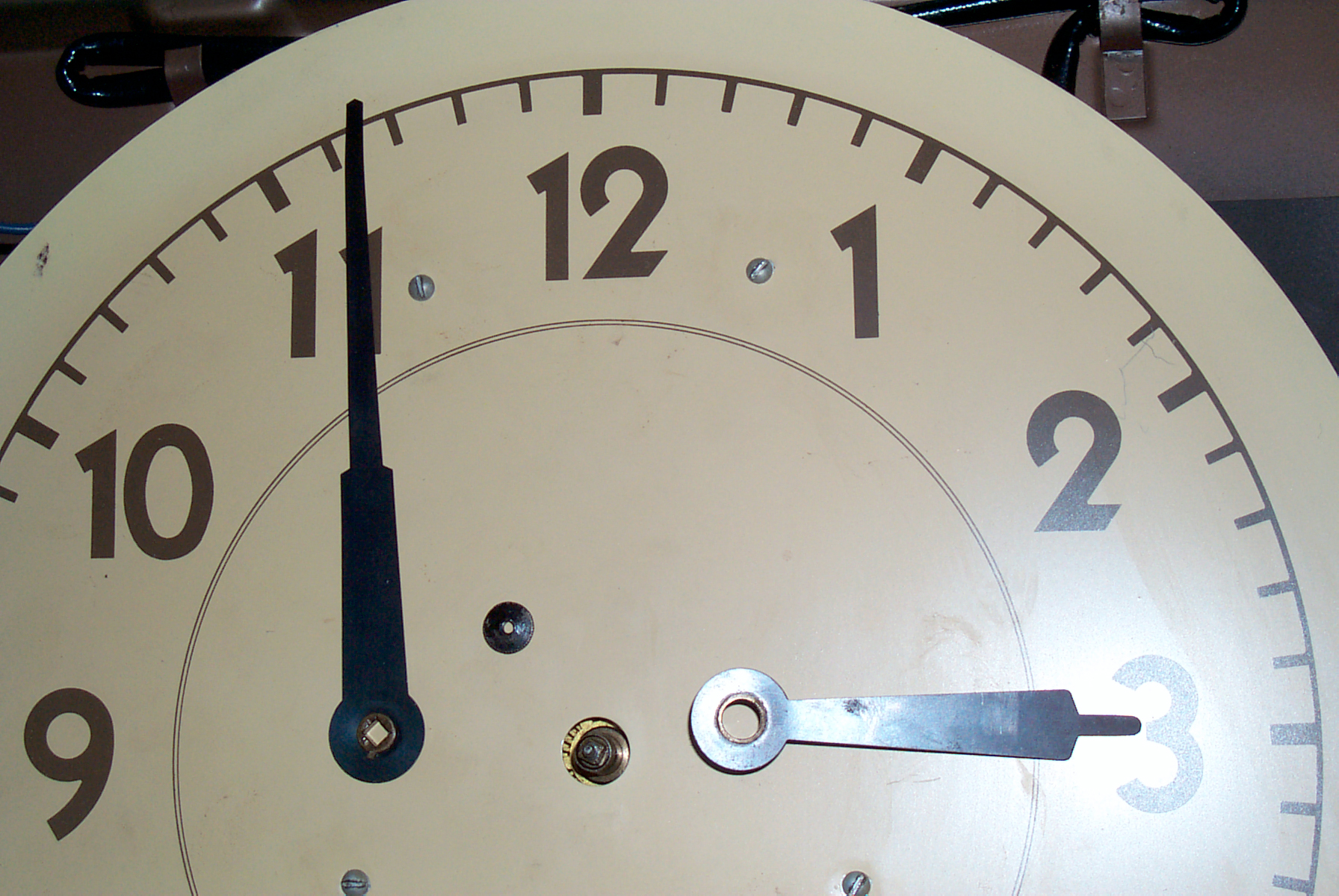
Fig 4 shows the knurled thumb nut removed and both hands lifted off. I've heard that the hole in the minute hand is not square. But my minute hand will set down on the square shaft in 4 positions without any binding. Also in Fig 4 you can see the 4 slotted round head screws that hold the dial. Although the minute hand might fit in any of four positions, only one will be correct for the synchronizing pulse. This was done so that lightning induced pulses that arrived for most of the hour would not reset the clock incorectly. So pay attention. If you loosen the knurled nut holding the hands when the clock is mounted on a wall the minute hand has a tendency to fall to 6:00. It's only when the knurled nut is finger tight that the friction clutch is working.
Fig 5 shows the clock now with dial removed and hanging on a peg nearby and the clock running. First while holding the clock on the table I wound the mainspring by turning the wheel that the bottom coil turns when it vibrates. I turned it until it hit the stop mechanism. Unbolting the pendulum and giving it a push would allow the clock to run for about 4 minutes. So I put a screw into a wall stud and hung the clock on it. Just the movement involved started the clock. The hands were at about 4:00 when it started and at 5:25 there was a noise that I think were the contacts closing asking for the electric wind, but now there's no batteries connected. I'm writing this with the clock showing 5:45 and I expect it to stop shortly. Stopped at 6:40 , run time about 2 hr 40 min. Set to 7:00, manually wound spring, started.
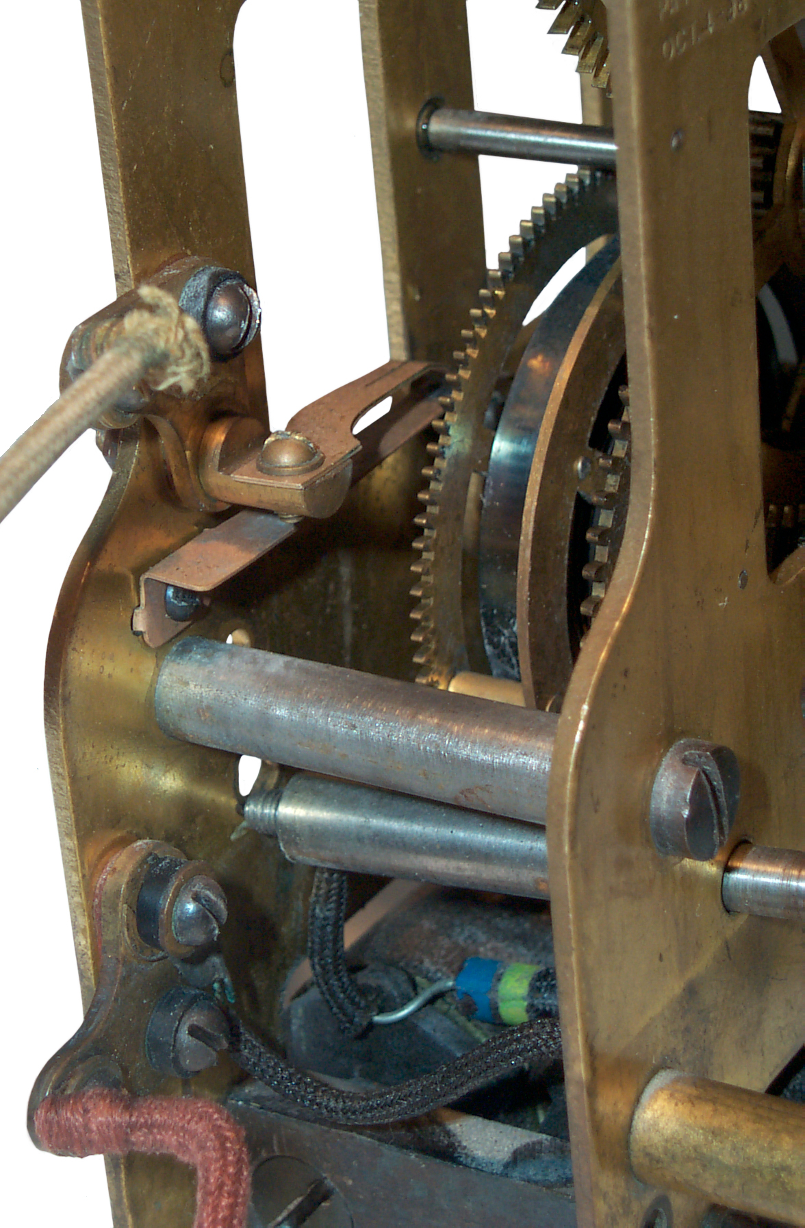
The escapement shaft sticks out in front, probably so those clocks that have the hole between the center and 12:00 can mount a second hand. I made up a paper dial 0.8" diameter and made the center hole slightly larger than the 0.076" dia shaft so that the shaft would not rub on it. Then made a second hand from 3x5 card stock with a center hole slightly smaller than the shaft and just pressed it on the shaft.
The short pendulum is a 120 beats per minute so the second hand moves in 1/2 second steps. The top of the pendulum is connected to the clock's rear frame with a short flexible metal band. Below the band there's a hinge that allows the pendulum to move forward and backward. So that when it's held solid against the frame with the shipping bolt installed it can move to the rear slightly. The clock movement connects to the pendulum by means of a stiff wire that's forged into a hole in the escapement shaft then goes behind the clock movement and down about 5" then has a horizontal projection that fits a slot in the pendulum support arm. This way when the movement is removed from the frame the pendulum stays with the frame. I expect that once adjusted the timing ability of a pendulum would not change if a new movement was installed.
Some simple wire tracing shows the a blue wire connects to both batteries and so must connect to + on one and - on the other to get a series connection. So 3 volts (two "D" cells in series) goes to the two free Green wires. Making this connection causes the winding electromagnet to hum and in maybe 10 seconds wind the clock. showing about 8:35. Goes about 30 minutes between windings.
The GE 43 red painted lamp did not light but it may not have been fully seated. Checks at 1.2 Ohms so looks good. Cleaned tip with eraser and reinstalled. It does light during Synchronization rather than winding. Powered by the local batteries, not the sync signal.
At the bottom of Fig 3 and Fig 4 you can see a raided section at the center that's just over an inch long. It may be that on earlier clocks a degree scale was attached here, but on all the metal cases clocks I've seen on eBay, none has a scale here. Nevertheless this hump can be used with the pendulum to level the frame. The center of the pendulum should move equally about this center marker for the frame. If the frame is out of plumb by some small amount the clock will stop.
Operating
Early January 2014 I installed a couple of printers and needed to move a clock like Fig 3 above. Also added the Ken's Clock 1900GS synchronizer and 2 "D" cell battery holder.
The battery holder includes some super caps to provide higher current pulses to the clock for winding and synchronization than you would get from a real No. 6 battery.
The synchronizer has a button at the top that you press briefly at the top of the hour to tell it the current top of the hour.
Then every hour thereafter it pulses the synchronizer coil in the clock.
Mounted the clock on wall and leveled it using a digital level good to a fraction of a degree. And pressed the synchronizer button.
But in a few days the clock was off by a couple of minutes. That's because the miinute hand had been manually turned to set the time and there was no longer a relationship between the top of the hour and the notch in the "heart" that the synchronizer needs to work. That's to say that the minute hand needs to be in a specific place on the shaft for the synchronizer to work.
To fix that I stopped the clock and manually rotated the minute hand a little and manually activated the synchronizer arm and keep moving the hour a little until I found the notch in the "heart" and while holding the synchronizer in moved the minute hand to the top of the hour. Then aligned the hour hard to the exact hour mark. Then at the top of the next hour started the pendulum.
To fix that I stopped the clock and manually rotated the minute hand a little and manually activated the synchronizer arm and keep moving the hour a little until I found the notch in the "heart" and while holding the synchronizer in moved the minute hand to the top of the hour.
The hour hand has not yet been moved to be right on the hour.
Clock is stopped here waiting to restart the pendulum.
The wind button has been pressed to wind the spring.
PS the top screw is in a stud and has a large flat head and is tight. It is tight enough that the case does not swing.
I might put a couple of push pins in the lower mounting holes just to be sure the case does not move, but it will be gilding the Lilly.
Also at this time I manually held the wind button until it stopped winding to be sure the spring was wound.
Then after an hour passed pressed the white synchronize button and put the cover back on.
Now to watch and see if it keeps good time.
Idea For Improvement
Instead of using 4.5 volts (3 each AA batteries in the synchronizer) it would be much better to use a high voltage (like in a throwaway flash camera) in series with a carbon resistor to get a much more lively and snappy synchronization that would also be able to synchronize a number of clocks connected in series.
I have a circuit coming from the UK that may be able to do this. More to come . . .

Dial
Movement
The "F" movement was used on many different SWCC clocks. All that's needed to work with different beat pendulums is to change the escapment gear to match the beat of the pendulum. There are two styles of second hand, one is a small hand placed on the shaft of the excapment wheel that's between the center and 12 o'clock on the dial. Some with a hole in the dial and some without the hole (Why?). The other uses a gear on the escapment shaft to drive a regular seconds hand that rotates about the center of the dial.
When used as a master or submaster clock switch contacts are fitted so that once per turn of the escapment when the switch closes, thus providing a 1 minute signal. This can be used via external relays to drive slave clocks or a combined day of the week and hour of the day bell program.
For an hour of the day only program the "F" movement can be fitted with a 24 hour wheel holding a disk with notches for the bell hours that works in conjunction with the minute hand to ring the bell at any minute in the day, but with at least 10 minutes between bells.
The pivot point for the escape wheel is on a short arm held by a screw thus allowing adjustment of the distance between the anchor and escape wheel. I'm sure there are a number of things that can be adjusted, some of which are not as obvious as this one.
Escapement
 See
my Self Winding Clock #2 Escapement
web page for a more detailed description of this method of
measuring the anchor.
See
my Self Winding Clock #2 Escapement
web page for a more detailed description of this method of
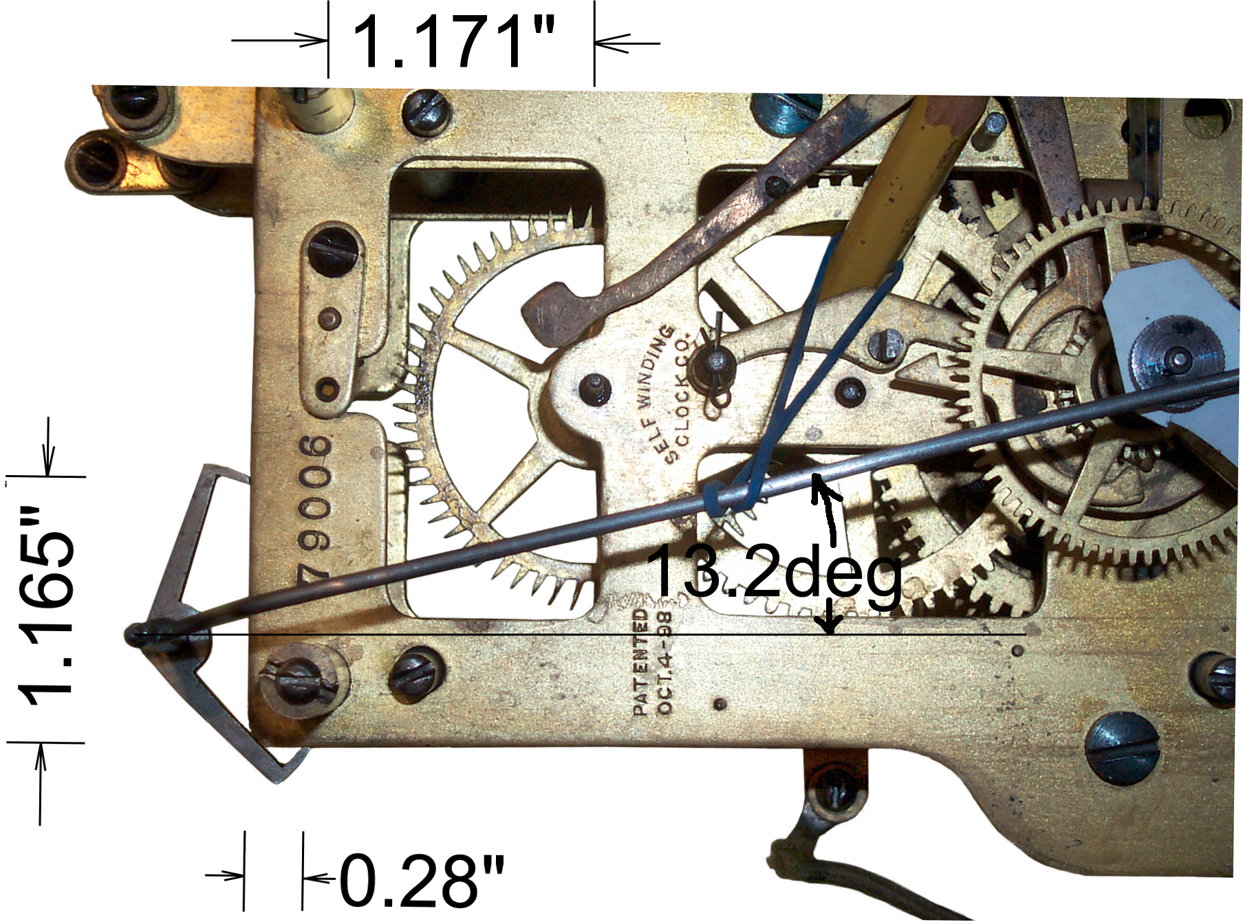
measuring the anchor.The distance between the pallet faces is 1.198".
The angle of the pallet faces is arc tangent (0.28/1.165) = 13.5 deg. The crutch angle shown in the photo was measured on the photo and agrees pretty well with the computed angle of 13.5 degrees.
In the photo the front of the clock is facing the camera but the back of the pendulum is facing the camera. So you can see that if the anchor was mirrored about the clock center line the left pallet face would then be horizontal and the right pallet would be vertical, which is correct for the Graham escapement.
The animated figure at http://www.abbeyclock.com/bbigrhm.html shows the anchor with the pallet faces moving away from horizontal and vertical by the swing of the pendulum. But in the W.U. clocks the pallet facts are much further away. Why is that?
Electrical
Winding Coils
(Blue Gray Black Silver = 68 ohms) soldered across the coil to reduce arcing of the switch contacts.
Inductance:
Synchronizing
578976 Electric Clock Setting Mechanism, C.M. Crook, himself, Mar 16, 1897,584128 Synchronizing Clock, J.H. Gerry, SWCC, Jun 8, 1897, .
954714 Synchronizing Attachment for Clocks, P.E. Burns, Dey Time Register Co., April 12, 1910, 368/52 ; 368/181
Manual_Sync.avi - manually activating synchronizing electromagnet when minute hand is near the hour.
SWCC39580b.avi - WU clock ticking, and to it's right Standard Electric Time Slave Clock ticking a minute.
Synchronizing Coils
These dual coils use a solid iron core.
DC resistance: 12.6 Ohms
Inductance: not stable?
3 volts @ 230 ma will operate the synchronizer.
Must be done within a few seconds (minutes?) of top of the hour.
The newer Self Winding Clocks use a single coil that has a laminated core.
Experiments Feb 2014
In order to make a high voltage drive for a number of WU
Self Winding clocks testing what size HV capacitor with
what voltage to get snappy synchronizing action.
When using a DC power supply set to 1.5 volts (120
mA, 12.5 Ohms) the action is very slow.
Try 187 Ohm series resistor because that's the value of
the first high power one seen in the 100 to 999 Ohm bag.
At 20.8 V using the 187 Ohm series resistor directly on
the power supply it takes a few seconds to pull in (104
mA)
This is way too weak for reliable operation, but does give
some idea about the coil: 1.35 Volts, 13 Ohms.
Voltage drop = .12 A * 187 Ohms = 22.4 V plus 1.5 V drop
across coil = 24 Volts capacitor charge.
120 uF 330 V photo flash cap - fast charge - just works
220 uF 100 V - very weak (long charge time -poor quality
cap)
2200 uF 50 V - fast charge to 0 current - snappy sync 1
second hold w/187 Ohm res
60 Volts through 187 Ohms is a strong
sync.
50 Volts through 187 Ohms will synchronize plus or minus 2
minutes from top of the hour reliably.
40 V through 187 Ohms works
30 Volts through 187 Ohms is too weak to sync.
Video of the sync
-------
______
The above video shows the sync working 2 minutes prior to
and 2 minutes past the top of the hour. But then it
appears to not work. I think this was caused by my
moving the clock hands relative to the heart shaped cam to
the point where they were out of sync.
DC Power
Synchronizing
I have a factory drawing that shows how to add a door bell button to a clock so that it can be manually synchronized. One of the two wires going to the button is connected to the left battery positive terminal and the other to the left Fahnestock clip. The Normally Open push button (doorbell button) is connected at the far end of the pair of wires. A short wire is connected from the right Fahnestock clip to the right battery negative terminal.The button is pressed one second before the top of the hour and released on the hour.
Ideas for a Modern Synchronizer
Dec 2008 - The modern radio synchronized "atomic" clocks are very convenient not only in terms of showing the correct time but also handling the switch to and from daylight saving time. It would be nice of the WU clocks could also do that. Note that you can turn the minute hand forward while the clock is running because there's a clutch in the drive train. So an electromagnet, like the pair of coils used in the winding mechanism or a more modern solenoid could be used to pull a pawl over the minute hand gear that would advance the hand one or more minutes for each actuation. Also a photo sensor could be arranged to sense when the minute hand was just prior to the top of the hour by more minutes than the pawl can feed. i.e. sense when to stop advancing the minute hand and get ready to use the normal hand synchronization method.Just like the "atomic" clocks you set the clock back one hour be advancing it 23 hours.
Instead of using a low drive voltage it would be much better to use a high voltage with a dropping resistor. A possible source of HV is the power supply used in throw away flash cameras. It's about 350 Volts which will work well. But it may be more energy efficient to lower the voltage to around 200 like was used when the clocks were in service.
A good source for the time and the DST information is the same radio broadcast used by the "atomic" clocks, i.e. in the U.S. WWVB.
This is really two different functions. The hourly synchronization can be done by one device and that can drive many clocks. The current limiting resistor needs to be set for the total series string of clocks. The DST advance and retard function needs to be a device that's added to each clock.
Once the optical sensor is in the clock it can be used to monitor the rate of the clock and give advice on setting the pendulum adjusting nut. It can also detect if the battery is low. This could be done by connecting a couple of wires from the clock battery to the DST circuit. This would both power the circuit and allow directly measuring the battery voltage.
2824218 Automatic Control for Clocks, T. R. Gilliland, Feb 18 1959, 455/204 ; 368/47; 968/511 -
2512462 Diversity System, Walter Lyons (RCA), Jun 20, 1950, -
2661091 Apparatus for Weight Classification, N. G. MALONEY,
2695491 Clock Correcting Means Controlled by Radio Signals, W.A. Kropp (IBM), Nov 30 1954, 368/47 ; 968/511 - WWV corrects a spring wound pendulum clock
2695492 Radio Time Signal Clock Correcting Means, Carl T. Young (IBM), Nov 30, 1954, 368/47 ; 968/511 - WWV corrects a spring wound pendulum clock
2699504 Automatic Tuning Device, Horace G. Miller (ITT), Jan 11, 1955, 334/24 ; 318/606; 331/177R; 331/35; 334/22; 455/162.1 - tunes RF transmitter
2734133 Electronic Control Circuit, J.J. Riley, - for resistance welder
2745015 Automatic Tuner, J. Stillman (ITT), - RF amp tank tuning
Called By:
3063233 SECONDARY STANDARD TIMER, Donald A. Bly (Hamilton Watch), Nov 13, 1962, 368/47 ; 368/187; 968/466; 968/520 -
3520128 AUTOMATIC TIME DISTRIBUTION SYSTEM, Novikov et al.- for correcting a system of clocks
5572488 Wristwatch paging receiver having analog message display, (Seiko) - watch had disks that revolve to show message through window
Clock Operation
I've heard from someone else that's running these clocks using a couple of "D" batteries and they need to be changed after 2 years. Not bad at all.
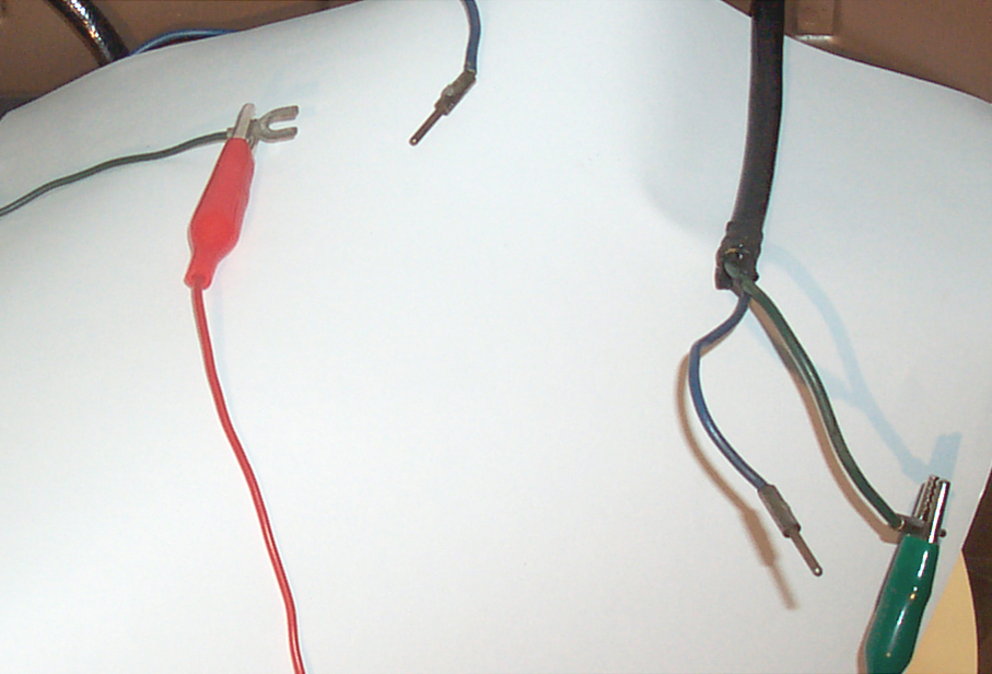 [This is my guess] So at some
point a new cable was run to each clock from a central power
supply. Then the clocks built after central power was
common changed from open end terminals that would fit under
the thumb screws on the No. 6 battery to pin tip plugs, like
were common on headphones, to plug into a connector on the
end of the cable. That may explain why this clock has
two tip pin plugs on the right side and one on the
left. The other left connector is the open ended
terminal on the green wire which is also connected to the
frame ground. That would be correct to connect to a
ground screw on the cable connector. Since the Blue
wire goes between the two batteries, when connecting an
external 2 battery pack just connect to the two green
wires. Using tip plugs would make it easy for a man on
a tall ladder to connect or disconnect the wire, much better
than screw connections. But the electrical code
probably requires a screw on the safety ground (green) wire.
[This is my guess] So at some
point a new cable was run to each clock from a central power
supply. Then the clocks built after central power was
common changed from open end terminals that would fit under
the thumb screws on the No. 6 battery to pin tip plugs, like
were common on headphones, to plug into a connector on the
end of the cable. That may explain why this clock has
two tip pin plugs on the right side and one on the
left. The other left connector is the open ended
terminal on the green wire which is also connected to the
frame ground. That would be correct to connect to a
ground screw on the cable connector. Since the Blue
wire goes between the two batteries, when connecting an
external 2 battery pack just connect to the two green
wires. Using tip plugs would make it easy for a man on
a tall ladder to connect or disconnect the wire, much better
than screw connections. But the electrical code
probably requires a screw on the safety ground (green) wire.Fahnestock clips (Telegraph Connectors) were supplied with the clock. The hole in the clip is the correct size to fit the threaded stud on a No. 6 battery. This would be a very good thing if you were the guy that got to climb a tall ladder to replace the batteries. Thanks to Larry K2JIA for clearing that mystery.
Also above each battery pocket there's a rectangular piece of insulation material attached to the frame and it's bowed out a little so there's a small gap from top to bottom at the center. What is this? my answer - If Fahnestock clips are used on the two No, 6 batteries, then it would be very easy for the clip on the negative terminal (the one connected to the outer Zinc can) to scratch through the frame paint and short out. Since the batteries are wired in series the potential from a negative terminal to ground might be 1.5 or 3.0 volts.
Do NOT do this

Whoever did this used two 6 Volt batteries for a total of 12 Volts! instead of using two No. 6 batteries (1.5 volts each) for the correct 3 volts! A 400% overload is too much.
The eBay ad says "The rewinding function is not now working".
I doubt the seller will get their asking price after burning up the motor coils.
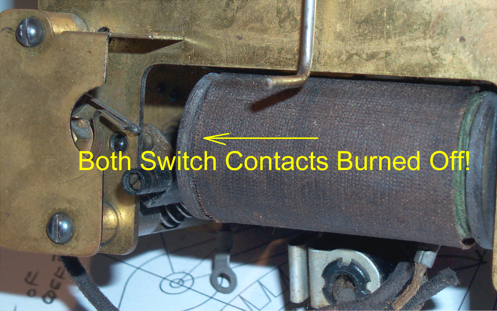
I got this clock expecting the coils to be burned out, but instead both winding switch springs have burned completely through so there's no longer anything for the armature to turn off. When powered from 3 volts the armature jumps up and stays there.
New Winding Motor Contacts
5 July 2007 - New motor contacts arrived.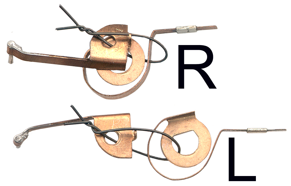 The new
contacts are marked L and R and as you can see in the photo
at left they are mirror images of each
other. Made By:
The new
contacts are marked L and R and as you can see in the photo
at left they are mirror images of each
other. Made By:Edward Stomner
P.O. Box 297
St. Germain, WI 54558.
The contacts marked "R" go on the front. It's easier to see that the spiral contact marked "L" goes on the back in close to the position shown at left with the flat in the washer hole level and at the top. When looking at the back of the movement the armature is on the Left and the spiral points to the right.
Problem with Winding Motor Coil Insulating Washers Rubbing on Rollers
 After
removing
the
old
contacts
to
remove
the
non
operating switch and installing only one new contact pair
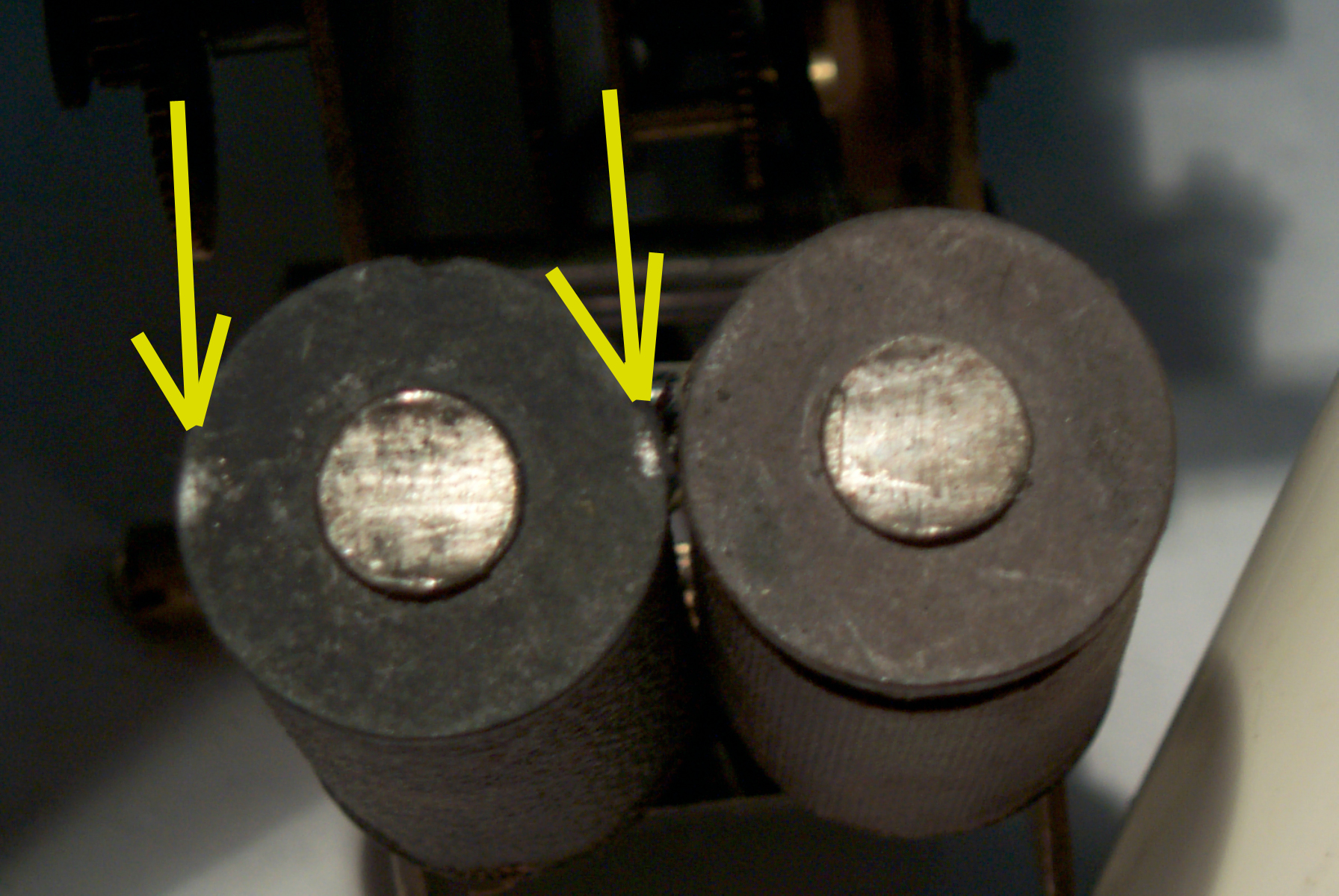
the motor did not work. After properly setting the
coil position the armature stuck when it was closest to the
coil. Running a piece of paper through the gap between
the armature and pole pieces on the coils confirmed they
were not hitting. But the roller was hitting the
insulating washer on the end of one of the coils. You
can see the shiny spots in the photo at the left where the
insulation is rubbing the roller. I've seen this same
problem on another Self Winding Clock and think the
insulation must be puffing up as it ages, maybe due to
moisture absorption?
After
removing
the
old
contacts
to
remove
the
non
operating switch and installing only one new contact pair
the motor did not work. After properly setting the
coil position the armature stuck when it was closest to the
coil. Running a piece of paper through the gap between
the armature and pole pieces on the coils confirmed they
were not hitting. But the roller was hitting the
insulating washer on the end of one of the coils. You
can see the shiny spots in the photo at the left where the
insulation is rubbing the roller. I've seen this same
problem on another Self Winding Clock and think the
insulation must be puffing up as it ages, maybe due to
moisture absorption?A few light strokes with a Mototool grinder almost fixed it. Still needed a little touch up with a file after installing and adjusting the coils. Now the motor runs fine on a single set of contacts.
To test the motor I remove the anchor so that the crutch rod is out of the way, but more important there is no spring tension. Then to check the strength of the motor stop the escape wheel and watch the winding cam side of the mainspring barrel. You can see that prior to stopping the escape when the mainspring barrel rear pointing pin is locked to the idler bar and the forward pointing pin on the hourly winding cam. After two turns the pins are on the opposite sides of the idler are indicating an almost fully wound mainspring. In about 3/4 of a turn the fixed stop causes the armature to stop in the up position drawing current.
Video1.avi
Video2.avi
These tests were run using a couple of "D" batteries with positive to the lower terminal with a red wire attached and negative connected to the movement frame, bypassing the hourly winding switch.
Hourly Winding Switch Problem
 The top
contact leaf is attached to a round post that is fixed to
it's base. To change the gap the leaf can be
bent. It's now working properly. This is
very different from the stack of 4 leaves uses on the sweep second "F" clock.
The top
contact leaf is attached to a round post that is fixed to
it's base. To change the gap the leaf can be
bent. It's now working properly. This is
very different from the stack of 4 leaves uses on the sweep second "F" clock.The red wire goes to the lower or positive terminal. The upper wire goes to the winding contact.
When the battery is connected to a fully unwound mainspring it does not wind since the winding cam is not being driven. Grounding the negative battery wire to the frame is the same a pressing the manual wind lever switch. Let it wind until it stops then release the manual wind power. Now as the clock runs down the mainspring the winding cam is being positively driven and when the high lobe comes up the winding motor will start. During winding the mainspring cage will rotate about one turn then the cam will be picked up and start to turn which will shut off the winding.
How Stiff do the Batteries Need to Be?
 Starting about 11 June the rate changed
from about 1 second slow per day to slower and slower rates
on each successive day. Indicating some type of
problem. I'm guessing the two "D" cell batteries in
battery holders are not strong enough.
Starting about 11 June the rate changed
from about 1 second slow per day to slower and slower rates
on each successive day. Indicating some type of
problem. I'm guessing the two "D" cell batteries in
battery holders are not strong enough. The minutes past the hour when winding occurs is controlled by the cam and seems to be constant at :08 and :32. I haven't come up with a simple solution to measure how long it takes to wind, but manually timing is prone to a second or two of error out of say 12 seconds.
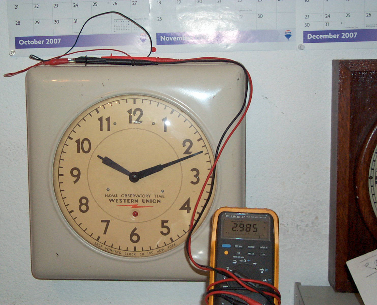
I'm not yet sure of how weak batteries may effect accuracy. So the first thing is to check on the batteries. The setup shown has a Fluke 87 Digital Multi Meter measuring the voltage across both batteries (nominally 3 volts) and the MAX/MIN function is turned on so each time the clock winds a new low is recorded. The Open Circuit Voltage is now 2.985 and at the last wind the minimum was 2.548 volts.
Have now changed the setup so that the winding current can be recorded using the MAX/MIN function. The clock would not self wind with the clip leads and series connected amp meter. But when I press the manual wind button it does wind. After that the peak recorded current was 296 ma although the average value I was seeing was around 150 ma.
The vibrating motor coil in my second S.W.C.C. Western Union clock is about 5 Ohms which would draw 500 ma from 2.5 volts or 600 ma from a fresh 3 Volt battery.
I thought about connecting a lab power supply to replace the batteries, but on second thought don't want to take a chance that the coil back EMF voltage spikes might blow out the power supply.
After disconnecting and reconnecting some of the wires, 15 Jun 2007, to do these tests the winding sounds stronger. Maybe a poor electrical connection is causing a problem? Need to get some Fahnestock clips.
Circuit Diagram
After tracing out the circuit diagram it's clear that the 3 terminals on the left of the movement (looking at it on the wall) are from top to bottom:- Battery Negative
- Frame Ground
- Battery Positive
- Battery Positive
- Frame Ground
- Battery Negative
Clock Stopped
8 Oct 2007 - The clock has been sounding weak and intermittent in it's winding and finally stopped because it did not wind. I replaced the two 1900L battery adapters with my home brew dual "D" No. 6 adapter that has both "D" cells in one housing supplying 3 volts in the left pocket.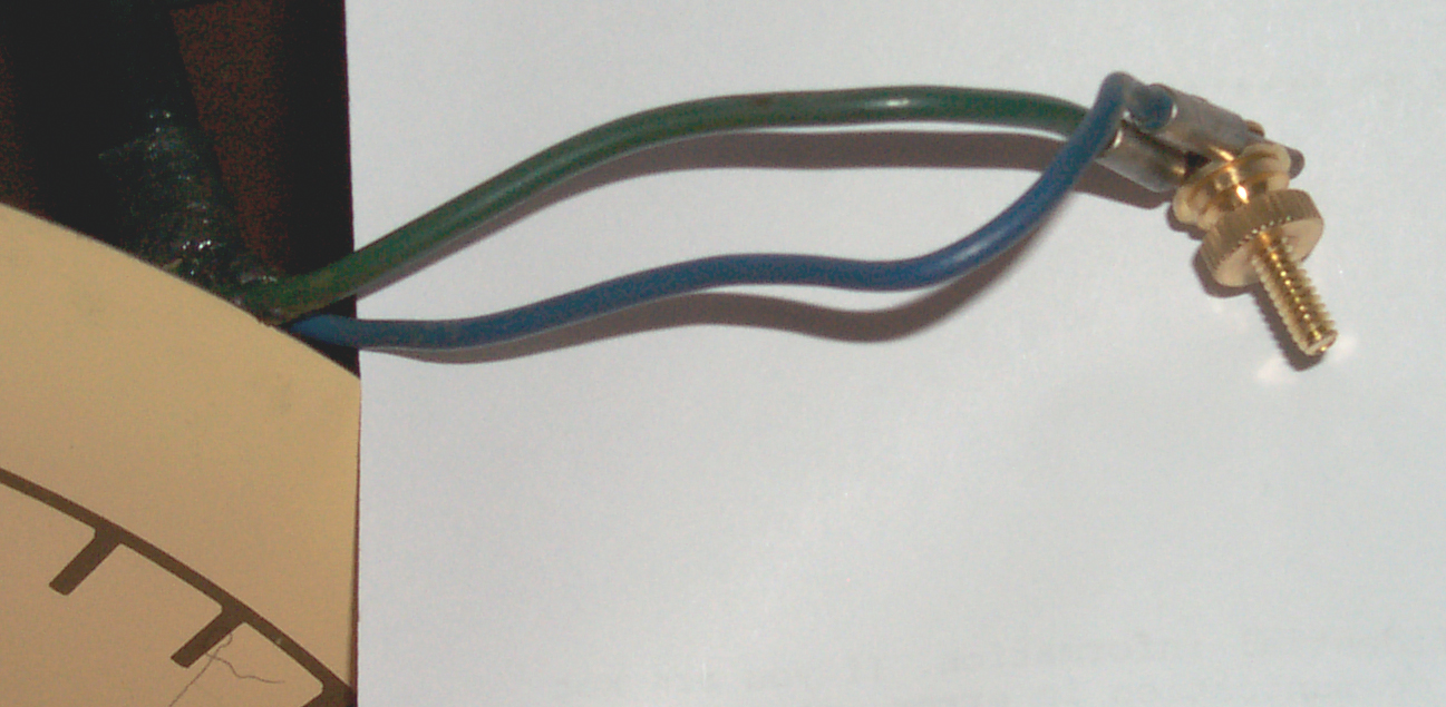 I shorted the right side battery tip
plugs by pinching them using a brass #6 screw, a couple of
flat washers and a brass #6 thumb nut.
I shorted the right side battery tip
plugs by pinching them using a brass #6 screw, a couple of
flat washers and a brass #6 thumb nut.The winding sound is now much stronger than with the 1900L battery adapters.
Note that a single cell 1900L has about 0.22 ohms resistance and a double "D" 1900L has about 0.12 Ohms. So when you put one of each in series you have 0.34 Ohms or the more common thing is to use two of the single "D" cell adapters the total resistance is 0.44 Ohms.
But the home made double "D" adapter has only 0.15 Ohms supplying the 3 volts. I think this is why it sounds stronger.
I don't know why the clock stopped winding. Both 1900L adapters show good on a battery tester and their internal resistance is the same as when I installed them.
One of the left battery wires has a "C" type terminal that fits well under a thumb nut. The other three wire ends all have tip plugs. Maybe I need to add some Fahnestock Clips?
Self Winding
5 June 2007 - checking winding times.
at 8 minutes past the hour the winding lasts about 8.2 seconds.
at 44 minutes past the hour the winding lasts about
Pendulum
It used to be that there was a physical "1 meter" bar that was the "standard" for length. In a similar manner there was a chemical cell used to define the Volt. But these have been replaced with definitions based on the second. The reason is that time can be measured much much much much much much much much much much much much much much much more accurately than anything else.
For a pendulum clock "g" is changed by the position of the Sun and Moon on the order of 1E-7 or 0.1 ppm and so that's about the best a pendulum clock can get.
From the pivot to the tip the length is about 11". The total swing is about 3/4" so the semi angle is about ATAN(0.375 / 11) = 2 degrees.
I've been told that the pendulum in this clock is compensated for both temperature and barometric pressure. I'm trying to see how that's done. After some searching I'm convinced that there's no barometric compensation and for use in the U.S. probably unnecessary.
I've been told the rod is Invar (Wiki) which is a metal designed for low thermal expansion. On the right side battery support is a notice about adjusting the bob that says this is a Type B pendulum. What is a Type A pendulum, if you know please tell me.
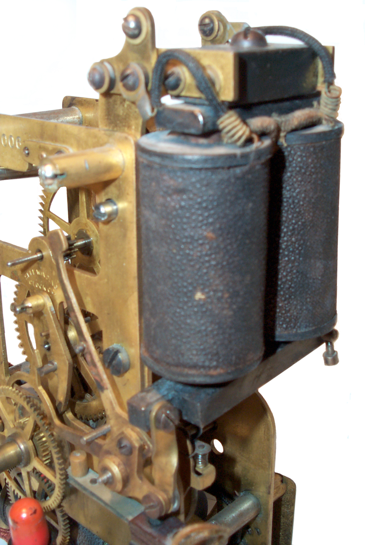
 Suspension
spring is maybe 0.003" thick. You can see it just
to the left of the two Fahnestock Clips.
Suspension
spring is maybe 0.003" thick. You can see it just
to the left of the two Fahnestock Clips.The hook at the very top of the pendulum that has a slit to clear the spring and it's brass plates can also be seen.
Below the left rubber washer holding the clock mounting plate to the frame is the switch for manually controlling winding. The mounting "D" hole is at top center. A small part of the anchor arbor (shaft) is visible in front of the top center of the rear brass plate. The crutch is attached to this shaft.
The weight of bob & rod about 1.5 pounds. Removed bob to make drawing. Adjusting nut is 4-40 thread
Jan 8, 2009 - There is a limit to how accurately you can adjust the pendulum nut. Maybe 1/4 or a little less of a turn. Since stopping the pendulum and restarting it changes the rate of the clock, i.e. you need to wait maybe a few hours after starting the clock before making any measurements on it's rate.
|
The Trick to making
fine adjustments to the rate
Set the pendulum nut so that the clock runs close to
the correct rate BUT is on the fast side. Then
use a candle to put a drop of wax on the pendulum
while it's moving. The added wax moves the
center of gravity down and slows the clock.Tried this but the candle wax did not make enough difference. |
Pendulum Shipping Bolt Down
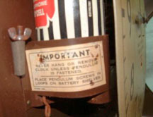 A very important feature of the
pendulum is that it's designed for shipping. First there
are a couple of holes front to back near the center of mass of
the bob and matching holes in the metal frame so that a screw
and wing nut can be used to bolt the bob to the frame.
There are also small long pockets next to each battery cup
designed to hold the screw and nut when the clock is
hung on a wall. At the top of the pendulum rod (see
photo immediately above) there is a "2 finger hook" that
attaches the pendulum to the suspension spring. The pins
at the top of the suspension spring run left to right and
since there's two of them the spring acts like the link in a
chain so that when the bob is bolted down the link allows the
rod to sit parallel to the frame.
A very important feature of the
pendulum is that it's designed for shipping. First there
are a couple of holes front to back near the center of mass of
the bob and matching holes in the metal frame so that a screw
and wing nut can be used to bolt the bob to the frame.
There are also small long pockets next to each battery cup
designed to hold the screw and nut when the clock is
hung on a wall. At the top of the pendulum rod (see
photo immediately above) there is a "2 finger hook" that
attaches the pendulum to the suspension spring. The pins
at the top of the suspension spring run left to right and
since there's two of them the spring acts like the link in a
chain so that when the bob is bolted down the link allows the
rod to sit parallel to the frame. I've read of many sad stories of people shipping pendulum clocks where the bob became a wrecking ball. That won't happen to this clock if the bolts are used! When they are not, it's a mess.
I think it's a ¼-20 bolt and wing nut.
Calculations
T = 2 * PI * SQRT(L/g)120 beats per minute means 2 beats per second or a period of 1 second.
On line gravity calculator for the U.S. gives Predicted gravity: 980003 +/- 3 milligals
On line Pendulum calculator (input: T=1.0 sec, g= 9.80003 m/s*s)
pendulum length (L) = 9.773109287977" or 0.24823697591462 meters.
enter T=2.0 sec, g= 9.80003 m/s*s and get 0.99295063933042 meter or 3.257712071294
If the clock was running perfectly the length would be as given above.
If the clock was running 100 seconds slow per day then:
entering T=1.001157 sec and g= 9.80003 m/s*s gives a length of 9.7957373456323"
or a change in length of 0.022628" or 44.19 TPI which seems strange. standard thread pitches might be 32 or 40.
 Start with 40 TPI and g = 9.8 m/s*s for
100 seconds/day change.
Start with 40 TPI and g = 9.8 m/s*s for
100 seconds/day change.nominal pendulum length (T=1, g=9.8) is 9.7731062962097" or 248.23689992373 mm
adding 1/40" to length gives 9.7981062962097" gives a new period of 1.0012782032604 sec
times 86400 seconds per day = 86510.4 or an increase of 110.4 seconds. Which is probably close enough.
The threads on a Brunell telegraph sounder are 8-40, i.e. a #8 diameter but with 40 TPI. It has a standard 4-40 thread for adjusting the height of the bob. The spring at the top is about 0.003" thick.
A line drawn 9.773" below the top pin supporting the pendulum goes through the center of the bob. The bob and rod up to and including the hook that hangs from the bottom of the spring weight about 1.5 pounds (+/- 0.5 pounds).
At the top of the rod there's a hook attached by a couple of rivets. At the bottom of the rod there is a short 4-40 threaded part attached to the rod by a couple of rivets. The brass bob adjusting nut supports the bob on it's top surface which is a little below the 9.773" radius. The use of rivets makes sense since Invar is hard to machine. Invar doesn't expand with heat, but cutting tools do so to drill you need a slow speed tool and plenty of coolant.
Using: T = 1 sec, M = 1.5 #, g = 9.80003 m/s*s, L = 9.773109287977"
gives: inertia moment or mass center (I) = 0.041926744315037 kilogram-meter^2
Barometric Compensation
1023140 Escapement Regulator, F. Ecaubert, April 16, 1912, 368/171 ; 368/170; 368/202; 968/130 - vanes projecting from wheel or bob.Class Numbers: these are watch balance wheel class numbers, not really for pendulum clocks, so 1023140 appears to have a wrong classification.
368 Horology: Time Measuring Systems or Devices/
368/170 - Oscillation or Reciprocating Means.Balance Wheel Type..With Regulation
368/171 - Oscillation or Reciprocating Means.Balance Wheel Type..With Regulation...by Compensation
368/202 - Regulation Means.for Compensation
968 Horology:
968/130 - Compensation of Mechanism for Stablizing Frequency..for the effect of atmoshpere pressure
Searching first 968/130: only 3 patents
1350035 Compensating Balance Wheel, I. Povelsen, August 17, 1920, 368/171 ; 368/170; 368/202; 968/127; 968/130 - non magnetic, extreme temperatures, low air resistance (marine chronometers).
1683648 Escapement Controlling Mechanism, C.H. Beasley, (Parkinson & W. & B. Cowan, Ltd.) September 11, 1928, 368/134 ; 368/182; 368/202; 968/130 - T = 2 * PI * SQRT(L/G) basic pendulum formula. R = D/L: Resistance, Distance over which the brake acts, pendulum Length. Used for a gas regulator that compensates for pressure and temperature.
Searching 368/171 there are 106 patents.
203976 Compensation Balance, C.V. Woerd, (Waltham) May 21, 1878, 368/171 - geometry involved in placing a number of weights around a balance wheel. Instead of the classic two temperature compensation this is an all temperature compensation.
617852 Balance Escapement, A.R. Colburn, January 17, 1899 368/127 ; 368/170; 368/171; 968/105 - all older patents in this class are for balance wheels, most like 203976 have a number of weights on the outside diameter in the form of screws.
895172 Compensating Controller for Timepieces, F. Ecaubert, August 4, 1908, 368/171 ; 368/202 - same inventor as 1023140 above
965503 Compensating Escapement Regulator, F. Ecaubert, July 26, 1910, 368/171 ; 368/170 - the strap spring that supports a pendulum is deflected by an mechanism to change the effective length for temperature compensation.
965504 Compensating Escapement Regulator, F. Ecaubert, July 26, 1910, 368/171 ; 368/170; 368/202 - for use on 400-day clock where the pendulum acts in torsion, i.e. rotates.
965505 Compensating Balance Wheel, F. Ecaubert, July 26, 1910, 368/171 ; 368/202 -
965506 Compensating Balance for Timepieces, F. Ecaubert, July 26, 1910, 368/171 ; 368/202
***965507 Escapement Regulator, F. Ecaubert, July 26, 1910, 368/182 - Both Temperature & Atmospheric compensation of pendulum
965508 Balance Wheel for Timepieces, F. Ecaubert, July 26, 1910, 368/171 ; 368/202
1048072 Balance for Clocks and the Like, W.P. Hinkleman, December 24, 1912, 368/171 ; 368/170; 968/103; 968/99 -claims to replace hair spring speed regulator and pendulum.
books.google.com link:
<http://books.google.com/books?id=2FUKAAAAIAAJ&pg=PA366&lpg=PA366&dq=clock+pendulum+atmospheric+pressure+compensation&source=web&ots=hB2VVqo5Da&sig=G6a-IWDmH16iDyMfd9Cp76nO3tg#PPA1,M1>
Part 1 is in The Observatory # 103 pg 384 and part 2 in The Observatory #104 pg 435. This is the publication of the Royal Astronomy Society and the Liverpool Astronomical Society. Volume VIII is for 1885.
The Sidereal Clock at the Greenwich observatory when GMT time started was made by Dent who made the Meridian Instrument. They were planning on using a Mercury bob, but Dent's Zinc and Steel bob worked so well the mercury bob was not used. The bob in the SWCC clock appears to be a zinc alloy? But the barometric compensation used in this clock was based on floating one end of a lever arm in the mercury pool at the base of a barometer and the other end of the lever arm moved a magnet up and down just below the bottom of the pendulum which has a couple of bar magnets mounted on either side. Thus when the air density is higher making the pendulum lighter an added downward force causes the pendulum to maintain it's weight. GMT started 1 Jan 1885. It causes the astronomers to set their clocks forward by 12 hours.
John Harrison of "Finding the Longitude" fame invented the Gridiron pendulum (Wiki) which uses the differences in thermal expansion of steel and brass (didn't have zinc then) to get temperature compensation.
The Wiki on pendulum clocks says the errors come from: temperature, atmospheric drag and local gravity.
But I've also read the the effect of atmospheric pressure is to change the air density, which changes the weight of the bob since the bob is floating in the air. In a vacuum the bob is significantly heavier than it is when the air is dense.
This plot showing the atmospheric pressure and running rate of a Synchronome clock clearly shows that the clock runs fast at low pressures and slower at higher pressures. This supports the idea that no air reduces air friction to zero allowing the clock to run faster. And also supports the idea that no air provides no buoyancy so the bob is heavier, just as if gravity was increased. From the formula for the period you can see that more gravity causes the period to decrease, or the clock runs faster in a vacuum.
If the drive power to the pendulum is near constant then less friction or more gravity will cause the swing to get larger. But as the semi angle gets larger so does the cycloid error (Wiki). So one way of getting barometric compensation is to have a drive mechanism that gives the pendulum the same drive power and somehow get the cycloid error to balance the barometric error. Testing this would require a way to measure the semi angle along with the barometric pressure in a controlled way and plotting rate vs. semi angle as the pressure is changed.
The Dent Astronomical Regulator Clock at the UK National Maritime Museum has "concentric tubular zinc and steel temperature compensated pendulum with cylindrical , matt-black painted brass cased bob" 1885 used till 1937.
508530 Mercurial compensation Pendulum, S. Riefler, November 14, 1893, 368/182
508760 Pendulum Escapement, S. Riefler, November 14, 1893, 368/134 ; 368/179; 968/98
Class 368/182 = Horology/Oscillating or Reciprocating Means.Pendulum type..With regulation...By thermal compensation
so for barometric pressure it should be 368/181 = Horology/Oscillating or Reciprocating Means.Pendulum type..With regulation
since it's regulation but not temperature.
In the book Watch & Clockmakers Handbook (1881) it suggests that by proper design Pendulum error (circle vs. cycloid) can be used to correct barometric error.
I've received two opinions that I respect and both have said that this clock does NOT have barometric correction. Also that in the U.S. there almost no need for it since barometers in most places don't change that much.
Temperature Compensation
The book suggests type metal (lead 70, tin 18, antimony 10 & copper 2%) is harder. Cast iron is very stable. The 3rd edition of the book has added information on the instability of some different Invar blends. Other possible rod materials are Zerodur by Schotts, ULE, etc.
Pendulum Table
This was the SWCC offering around 1908| Style |
b/min |
Description |
bob # |
| 1 |
60 |
Mercury
Compensated |
15,
30 |
| 2 |
120 |
Wood
Rod |
2 |
| 3 |
60 |
Wood Rod | 6,
10 |
| 4 |
140 |
Wood Rod | 0.75 |
| 5 |
84 |
Wood Rod | 10 |
| 6 |
72 |
Wood Rod | 2 |
| 7 |
80 |
Wood Rod | 2,
4 |
| 8 |
140 |
Wood Rod | 2 |
There must be more pendulums
| Style | b/min | Description | bob # |
| A |
? |
? |
? |
| B* |
60 |
Invar
Rod 9.77" length to c.g. |
1.5#
lead or type metal |
Synchronizing
954714 Synchronizing Attachment for Clocks, P.E. Burns, Dey Time Register Co., April 12, 1910, 368/52 ; 368/181
Manual_Sync.avi - manually activating synchronizing electromagnet when minute hand is near the hour.
SWCC39580b.avi - WU clock ticking, and to it's right Standard Electric Time Slave Clock ticking a minute.
The regulator nut on these 120 beat clocks is one turn for 100 seconds per day. I haven't yet figured out the knurling pitch to see what one knurl of change is in time. But it's hard to make a fractional turn of a know amount since there's no calibration. If you got the nut to within 1/10 turn then the clock might be off by 10 seconds per day. So an hourly synchronization would keep on within a second.
An error of 100 seconds in a day translates to an error of 4 seconds in an hour so the regulating nut only needs to be set to a quarter turn if the clock has hourly synchronization to be accurate to 1 second..
Lubrication
Adjusting Rate
Step 0 Mounting
Figure 2. On the back of the frame at the top center there's a big hole with a slot pointing upwards. The idea is you install a screw with a large head into a stud. Then the clock can be hung on the screw without any tools. After it's plumbed, or better after the beats are set equal, you use the lower left and right mounting holes to anchor the clock to the wall. On the back of the frame these three mounting locations protrude slightly from the plane of the square frame edge. The idea is that the frame is only fixed at three points. That's way my frame is not flat against the wall.If you look down at the top center when the clock's mounted on the wall with the cover installed there's a hole about 1/4" diameter. This is composed of a groove in the front of the frame and a notch in the cover. This is where the synchronizing and/or DC power cable enters the clock.
Step 1 Set the Beat
The older instructions say to just have the pendulum swinging over the center of the frame. But that's really not as good as tilting the frame so the the time between beats is equal. If a photo detector is placed so that it's interrupted by the pendulum you can get a very good measure of the period, but not the length of each beat. A microphone would hear each beat, as does your ear, but even when properly adjusted the beats may sound different so I don't think a microphone is a good way. The best way is probably some type of sensor (or sensors) activated by the anchor or escapement wheel. (contact mike that's part of an alligator clip.)Methods
- I taped a strip of paper to the frame, but a piece of
3x5 card stock would have been better so that the top edge
could be just below the bob when it's at dead
center. Taped a narrow pointer made of paper to
approximately the center of the bob. Manually move
the bob slowly back and forth listening for the click as
the pallets strike the escapement wheel. Mark the
left and right points. Make a new mark half way
between these (in my case this was less than a half
inch). Note the total swing is much greater than
these two points.
Now rotate the frame to bring the pointer to the center position. - This method depends on looking at each of the pallets in relation to the teeth on the escapement wheel. Something my eyes are not up to.
- The Microset by Bryan Mumford has a Beat Error Mode that works by measuring the time between beats. Just rotate the frame until the error is zero. Since the Microset is a small hand held device it's easy to bring it to the clock.
I've also installed a couple of Radio Shack 270-403A single "D" battery holders and wired up the clock so that the cover can be installed. I needed to change the minute hand since it was off 90 degrees. And have manually synchronized to clock by squeezing between the top and bottom of the electromagnet at 1 second to the hour and releasing at exactly the hour.
Then installed the cover. Now we'll see how it's running. With the cover off and before setting the beat it was running about 1 to 1.5 minutes slow per day.
3 Oct 2007 - In The Science of Clocks & Watches by Rawlings, he says an off beat clock will keep the time as well as one on beat. But an off beat clock will stop sooner. So it may take more power to run the off beat clock. If you have data let me know.
Set the Time
The minute hand can be moved forward to set the time, but on my clock after doing that the minute hand does not seem to advance. So I used the lever switch to manually wind the clock and the shaft made a little over one turn. After that the minute hand is moving normally. So maybe if you're going to stop the clock you do it just prior to a wind so that it can be would after setting the minute hand when you're done.Another possibility is that this is a problem related to why my clock winds twice per hour?
Step 2 Adjust the bob
To adjust this clock you need to stop the clock, turn the
adjusting wheel in the pendulum ( Left = slower, R = faster)
and restart the clock. After adjusting let the
clock run for at least a day, maybe longer before making
another adjustment. Note it can take a few hours for a
pendulum to stabilize so you can not check the rate until
that's happened.Since it can take hours for the pendulum to stabilize after being restarted it would be advantageous to allow for adjusting the period while the clock was running. The stabilization time would be much shorter. Self Winding Clock Co. has a patent to do just that.
393638 Pendulum Regulator for Clocks, J.H. Gerry, 27, Nov 1888, 368/181, 368/271 - but so far I've never seen one. It works at the top of the pendulum suspension by moving it up or down changing the length of the pendulum.
I wonder if tilting the clock can be used for fine adjustment? ans. No. The frame should be adjusted so that the time between beats is equal.
Also, since this clock does not have an official second hand, how do you reset the seconds? Ans: No need since as accurately as it can be read is some fraction of a minute.
19 May 2007 7:43 am - In order to check the rate the dial is back on. Like the Standard Electric Time Slave Clock, you can turn the minute hand (forward only) to set the time. The minute hand moves in 1/120 minute steps which for all practical purposes is an analog movement. But to be technical it's really a digital movement. With the dial installed I can't see the second hand so it will take longer to check the rate. Well maybe not. The minute hand is the same width as the wide minute mark used at each 5 minutes of time (the hour marks), so by watching for good alignment you can recognize to at least a couple of seconds, maybe better, when it's the top of a 5 minute minute interval. At the top of the 8:00 hour it was spot on.
21 May 2007 - 9 pm Using two "D" cells for power, one in each battery pcoket, have synchronization at 9 pm. and outer cover installed.
22 May 2007 - 7 am about 1 minute slow in 10 hours, or 2.4 min/day. But this may be part of the setteling process, need more time.
23 May 2007 - 8 am slow about 3 minutes, which is a rate of 2 minutes/day. waiting for literature that has the cal factor for the pendulum adjusting nut.
24 May 2007 - 7am slow about 6:20 in 58 hrs or -2:37/day
24 May 2007 - 9 pm slow 8:00 in 62 hrs or -3:06 /day <- ? accuracy of delta
25 May 2007 - 8:30 pm slow 9.5 min @ 95.5 hrs or 2:23 per day The Clock on the right is a slave that was just set and the 19" wide box on the bottom is a Cesium standard running 3E-14 slow. 3 Clocks photo.
On the right side battery can it says:
120 Beat Type B Pendulum
If clock gains turn regulating nut to the left.
If clock looses turn regulating nut to the right.
One turn of regulating nut changes rate 100 seconds in 24 hours either fast or slow.
So one and a half turns to the right minus a little. Done 9:15 pm. Both batteries check good. Cover back on.
26 May 2007 7:15 am - Clock was stopped. The jiggling caused by taking the cover off triggered the self winding. There may be a problem with the switch that activates self winding. It winds in a pattern of 24, 36, 24 minutes between winds but the cam only has one lobe so it should wind once per hour. When the hands are manually turned (clockwise only) the relation with when winding occurs is changed.
27 May 2007 7:45am - Clock is about 45 seconds slow, but that's about where it was last night. Hard to tell the rate this soon. It's winding at 10 and 45 minutes past the hour.
27 May 2007 9:45 pm about 1 minute slow in 38 hours or 38 sec/day slow
28 May 2007 8:45 am about 1:15 slow in 49 hr or 37 sec/day slow
28 May 2007 4:30 pm about 1:30 slow in 56.75 hr or about 38 sec/day slow or 0.38 turn to Right.
28 May 2007 7:30 pm restarted after making some measurements
29 May 2007 6:40 am - too close to right on to tell anything. (winding at :08 and :44 minutes past the hour)
30 May 2007 7:30 am too close to right on to tell. 36 hrs <10 sec so less than 6 sec/day
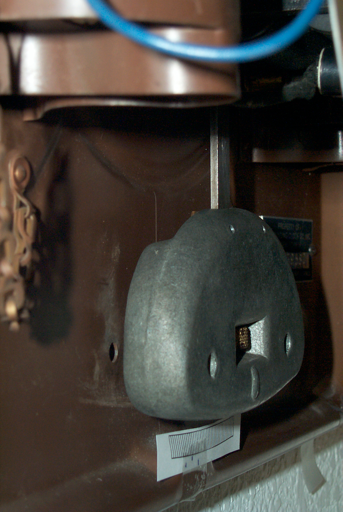
30 May 2007 3:00 pm - restarted clock w/manual sync). For some unknown reason it stopped while having it's picture taken (see above bob photos).
31 May 2007 6:00 am - maybe 10 seconds fast in 15 hrs. The winding is now at :08 and :32 minutes past the hour. Before it was at :08 and :44, so it looks like the :08 past the hour is the real hourly cam and the :32 or :44 minutes past the hour is a bug.
2 Jun 2007 7:00 am - within a few seconds after 64 hours < 1.1 sec/day
4 Jun 2007 7:00 pm - Looks to be right on the money<3 sec in 124 hrs or <.5 sec/day
9 Jun 2007 9:00 pm - Within 5 seconds in 246 hours or better than 0.5 sec/day - It's a lot easier to set this clock than to set the quartz clock driver for the Standard Electric Time Co. slave clock which is now overe 1 minute fast.
10 Jun 2007 9:00 pm - running 11 seconds slow in 270 hours or 0.97 sec/day slow. - new measurement method. First look at the reference clock seconds count and listen to this cock's beat. While continuing to count the time of the reference clock, keep counting until this clock has the minute hand pointing straight up. In this case the count was past the hour so this clock is slow by the count. If the minute hand was straight up before the count of 60 the clock would have been fast. This method is much more accurate than trying to guess the seconds by "reading" the minute hand.
11 Jun 2007 9:00 pm - 22 seconds slow in 294 hrs 1.8 sec/day
12 Jun 2007 10:00pm - 29 seconds slow in 319 hours or 2.2 sec/day - appears to be slowing down?
14 Jun 2007 10:10 pm exactly 1 minute slow in 367 hrs or 3.9 sec per day - is slowing down & accelerating, battery or the warm weather?
18 Jun 2007 6:00 pm - clock reads 6:00:00 actual time is 6:01:38, clock is slow by 1:38 in 459 hrs, or 5.1 sec/day. Still slowing down. I was expecting the rate to remain constant. It's been hot the last week or so, maybe that's related.
19 Jun 2007 11:30 pm clock reads 11:30 , actual time is 11:31:52 1:52 slow in 489.5 hr, or 5.5 sec/day slow.
20 Jun 2007 3:00 pm clock is 2:00 min slow in 505 hrs, or 5.7 sec/day
28 Jun 2007 3:00 pm - slow 3.00 minutes in 673 hrs or 6.42 sec/day (IMP2 driving the SET slave clock is 3:44 min fast, poorer than the pendulum)
15 July 2007 9:00 am - slow 4 minutes in 1075 hrs or 5 sec/day.
30 Jly 2006 - 34 sec slow - I forget if it was changed between 15 & 30 July?, don't think so. Wonder if there's coupling to the 37SS across the room?
10 Sep 2007 16:45 - 27 sec slow measuring from 30 July it's been 42 days and the time has advanced 7 seconds, or 0.16 seconds/day. Pretty good.
Stability
- Bent winding contacts up slightly so point does not
cause winding.
- Installed Ken's battery adapters
- moved adj nut right 0.1"
- manual synchronized at 10:00am - non effective, minute
hand wrong 1/4 hour, reset minute hand.
- See Fig 6 at top of page
Synchronization only sets Minute hand, not seconds
Minute hand square shaft
Now winding at 37 minutes past the hour.
The two "D" cells that were installed a couple of months ago test in the middle of the green, i.e. like a new battery.
Regulating large square metal case clock
29 sep 2007 sync at 3:00 pm
1 Oct 2007 - clock slow by 4-1/2 min or 135 seconds per day. one turn on nut right -
12 Jan 2010 - will try the candle wax method on this clock. It's been running for a couple (+) of years on the same home made two "D" cell battery adapter.
12 Jan 2010 set at 6:40 am
19 Jan 2010 clock 4:52 actual time 4:45 so 7 minutes fast in 7 days 10 hrs 5 min 6.55E-4 rate
22 Jan 2010 - reset clock to 10 am and added a couple of drops of red candle wax to pendulum while it was running. Done from the left side.
23 Jan 2010 - actual time: 12:43, clock time 12:44, i.e. 1 minute fast after 1 day + 2h43m, 6.24E-4 rate (added much more wax)
24 Jan 2010 - acutal time 5:42 pm, clock time 5:44 pm, i.e. 2 min fast, still gaining? Wait another day or so.
31 Jan 2010 - acutal time 8:30 pm, clock time 8:40, i.e. 10 min fast since 23 Jan 12:43 pm
when it was 1 minute fast, gained 9 minutes in 8d 7h 47m (11987m) for a rate of +7.5E4 - bummer it's not getting slower.
Patents
274324 Circuit For Electric Clocks, V Himmer, TTC, Mar 20 1883, 368/184
274325 Electric Clock, V Himmer, TTC, Mar 20 1883, 368/160 ; 235/131R
305632 Secondary Electric Tower Clock, C.H. Pond, TTC, Sep 23, 1884, 368/59 ; 235/131R
Pond Self Wind - the early patents above were prior to the founding of the Self Winding Clock Co.
Self Winding Clock Co. patents:
362902 Circuit Controller for Self Winding Clocks, C.H. Pond, May 10, 1877, 368/149
411168 Gong striking mechanism for synchronized clocks, C.H. Pond, Self Winding Clock Co, Sept 17, 1889 -
584128 Synchronizing Clock, 8-Jun-1897, 368/60 ; 368/187 -
611822 Electric Time Switch, 4 Oct 1898, - 307/141 ; 185/40B; 200/38DA; 368/149
966038 Clock, Frank W Moore, Aug 2, 1910, 368/150; 368/124 - This is a self winding clock, but long after the 611038 patent, why was this one granted?
I found it because of a patent citation on 2531121, Mechanical time fuses.
Books
The Science of Clocks & Watches, 1993, A.L. Rawlings, 3rd Ed, ISBN10 0950962139 - Third edition has new comments by a number of B.H.I. members. General book about precision pendulums like used in observatories. Not directly related to SWCC clocks. Aimed at precision clock design. The first edition was done in 1944 and the second in 1948 were both all the work of Rawlings so the comment of page 56 was his thinking around 1948
Accurate Clock Pendulums, 2004, R.J. Matthys, ISBN 0198529716 - a close experimental look at what effects the stability of the pendulum. A huge amount of work has gone into looking at various questions experimentally. But the key questions may not have been asked. For example when looking at the bob many shapes were considered based on had been proposed by others, but when looking at the rod only circular was considered. A rectangular rod was not mentioned, yet the SWCC clock uses a rectangular Invar rod. A good thing about the book is that it puts a number on the various errors so that you can go after the larger ones first instead of wasting time fixing a small error to no advantage. No mention of composite carbon fiber for rods.
The Modern Clock - A study of Time Keeping Mechanism; It's Construction, Regulation and Repair by Ward L. Goodrich, 1984, ISBN 0-930 163-23-0 - Some details on escapment design.
- Information on the "A", "C" and "F" Self Winding Clock Co. movements and their adjustment. The wording and methods are different from those in the "F" manual, haven't figured out which is newer. First ed. of Modern Clock was 1905, second ed. was1950, so this info may be more up to date than that of the "F" manual. Recommended.
- Also a comment about slave clocks not working in general and how they keep track of their own errors. The main error is either failing to advance or advancing too far during the instant when the advance is supposed to occur. The only way around the problem was patented by Standard Electric Time for their tower clock and uses a worm gear that can not be turned backwards.
- 2242654 Inpulse Timepiece, W.E. Maxwell, Standard Electric Time Co, May 20, 1941 368/60; 368/185; 968/549 -
- 2242655
Inpulse Timepiece, W.E.
Maxwell, Standard
Electric Time Co, May 20, 1941 368/58;
968/551 -
Product Ideas
- Low cost Battery Adapter
- Hourly Time Synchronizer that's "Atomic" accurate - the watch crystal units are far from accurate.
- Operation monitor
- Help for equalizing the beat when installing
- monitor some key clock parameters
- Help for setting the bob height
- Precision pendulum position sensor - Instead of just getting an on/off signal once per period, get the pendulum position in real time.
- A slave driver that has a fast time constant.
That's to say uses high voltage and series resistor to
lower L/R.
YouTube
Connections Museum: Self Winding Master Clocks in Central Offices, 12:07 -
J. Alan Bloore: SWCC Play List -
Serial #'s - Self Winding Clock Company "F" movement - What they reveal, 7:15 -
<=63132: up to 1908
s/n
Year
<=63132 <=1908
112956
1917
196212
1929
Links
Standard Electric Time Co Slave Clock
Henry Weiland docs & photos - an ftp site with some great information.
Ken's Clock Clinic - SWC Restorations & Battery Holder/Synchronizer (looks like two No. 6 dry cells)
Mumford Horology - Microset
Mark Headrick -Western Union Clock - Graham Escapement (animated)
Self Winding Clock Co Hairspring Mvmt -
American Clocks Vol. 2, Including Self-Winding Clocks -
Self Winding Clock Company Model "F" Movement Technical Manual
Universal Impulse Driver for Slave Clocks - one of the intervals is 60 minutes between pulses just for this clock. TCXO is an option.
Western Union Clock - assembly photos
New York Times - A Clock Moves in Grand Central, and Memories Stir - asked how they do the hourly sync