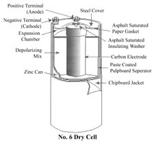
No. 6 Dry Cell
Brooke Clarke 2007 - 2024
Background
Third Prototype
Second Prototype
Post Mercury Ban Alkaline
Modern No. 6 Battery
"F" Dry Cell
Comparing Modern No. 6 Dry Cell and a 6 Volt
Lantern Battery
Inside the 6 Volt Lantern Battery
Testing on the Electro-magnetic Toy Engine
The Build it Yourself! a Real Electric Motor kit
Low Cost Battery Adapter
Hardware
Teeth on Pliers
Internal Resistance Measurements
Eveready W.W. II ad for the No. 6 Dry Cell
Flash Amps
Measured Flash Amps
Calculations
Two D Cells Series or Parallel
Seagull R40 Batteries
Joseph Henry
Applications
Patents
Eveready Pocket Amp Meter
Sterling Manufacturing Co
Conn Tel & Elec Flash Amp
Meter
Dual Range Pocket Voltmeter
Yankee Volt_Ammeter
Links
Background
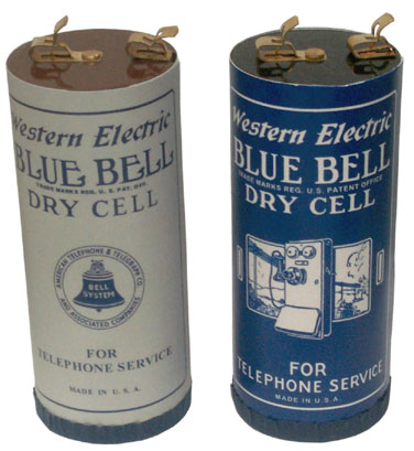
The
wet
battery gave way to the dry cell opening up many portable
applications that were not possible with a glass jar full of
liquid chemicals. These first generation Zinc Carbon cells
were the common type through the
Korean
Conflict. They consisted of a Zinc cup which is
the negative terminal just like the Zinc in a wet battery is the
negative electrode. The metal cap on the carbon rod is the
positive terminal. Some type of insulating material was
poured between the cup and rod at the positive end to seal the
battery. The label was a cylinder of single layer cardboard
on
flashlight
batteries and there was a bottom cap on the No. 6 Dry
Cell. Modern designation is LR40 for the size or ALR40 for
Alkaline. The body of a No. 6 Dry Cell is 2½" diameter and 6"
tall. The terminals are #8 Thumb nuts or optionally
Fahnestock Clips.
The Zinc gets consumed in this chemistry so if a battery is left
connected to a load or just left on the shelf, after some time the
Zinc will have holes that allow the liquid electrolyte to leak
out.
Maybe the No. 6 came after No. 1 through No. 5? The No. 6
replaced glass batteries on a one for one basis in clocks,
telephones and many other applications. In the 1950s these
were available in almost any hardware store. In 2007 they
are only available from specialist internet or mail order houses.
I think this drawing is from the 1980s so may be the last
incarnation of a real No. 6 Dry Cell.
In TM 5-234 Topographic Surveying 1953, wiring diagrams are shown
for No. 6 batteries where the voltage is 1.5 Volts per cell and
the current is 24 Amps per cell. Paragraph 243 Power Supply, page
138, Fig 31 Methods of Connecting Batteries.
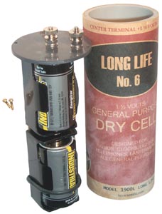
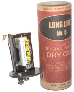
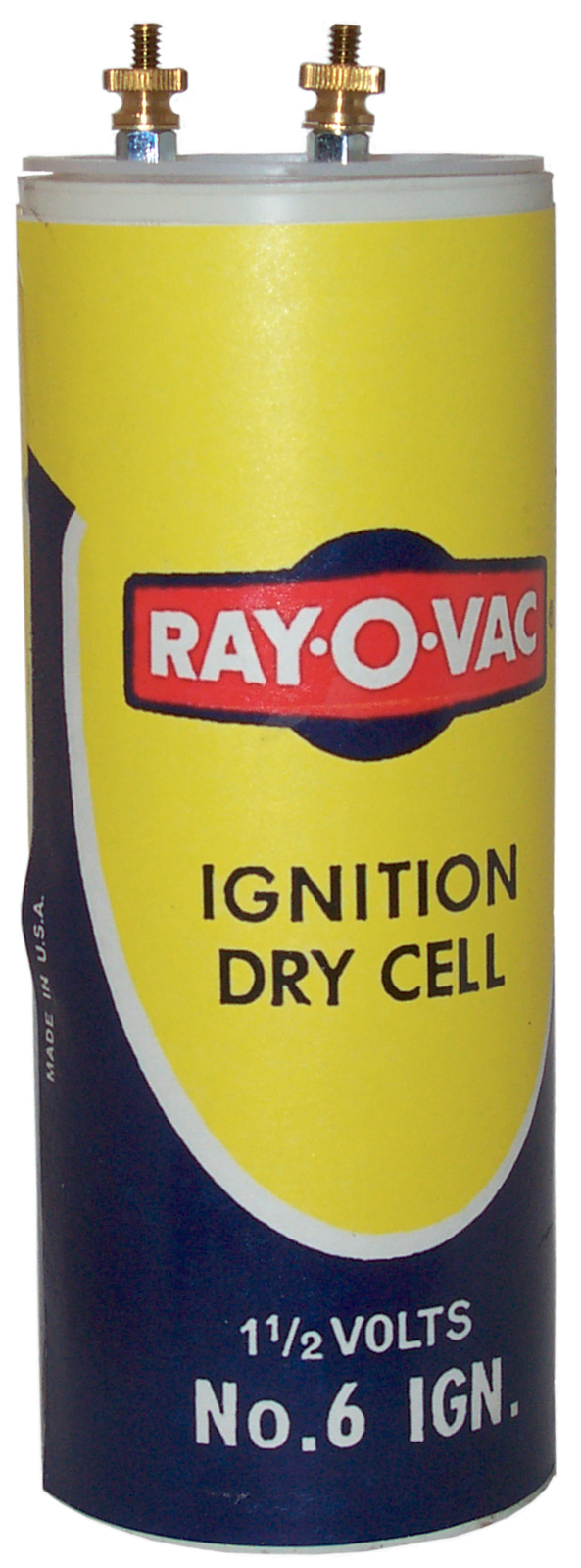
Third Prototype
The simplest (lowest cost) version that retains excellent flash
amps uses a single "D" cell battery holder. Top hardware is
# 6 so the optional #6 Fahnestock Clip will fit. Internal
heavy wiring is soldered to the battery holder and crimp to # 6
ring tongue terminal.
Instead of putting a terminal in the center, it's offset a little
to provide a 1 inch center to center distance between the two
terminals. This is the unit shown above with the Ray-V-vac
label.
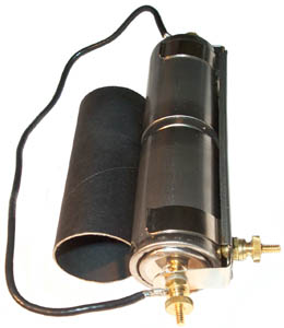
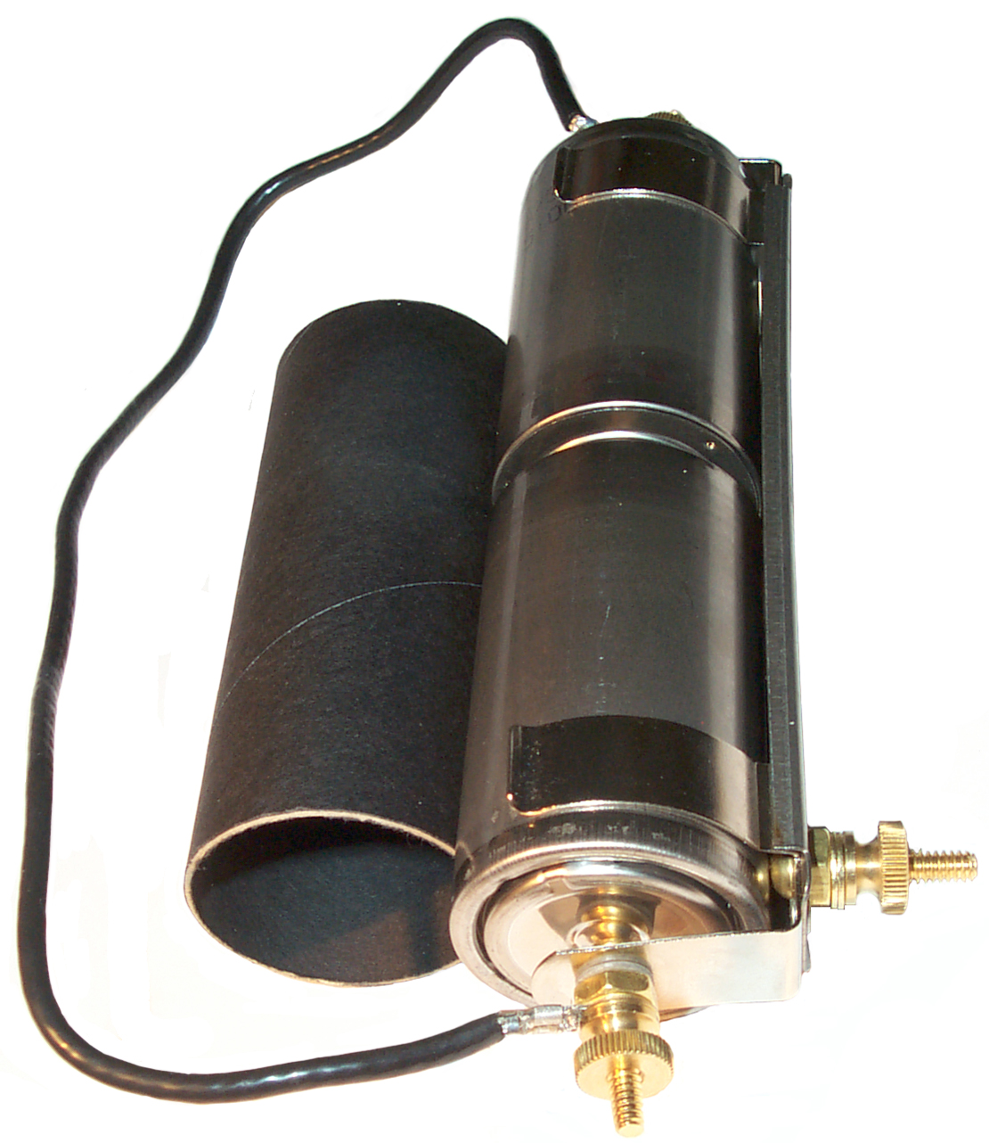
Second Prototype
 This is
based on the same concept of using test caps for the ends and PVC
pipe for the tube. I've found a combination of fittings that
allows the user to choose either Fahnestock Clips or thumb screws
(maybe also an option for Wing Nuts which were commonly used in
Europe then you don't need pliers to tighten the thumb nuts.
Ever wonder what those "teeth" on pliers were
for?). Note if you add Fahnestock Clips under the thumb nuts
then you can not depress the clip far enough to insert a tip
pin. Notice there's a tip pin installed in prototype 2.
This is
based on the same concept of using test caps for the ends and PVC
pipe for the tube. I've found a combination of fittings that
allows the user to choose either Fahnestock Clips or thumb screws
(maybe also an option for Wing Nuts which were commonly used in
Europe then you don't need pliers to tighten the thumb nuts.
Ever wonder what those "teeth" on pliers were
for?). Note if you add Fahnestock Clips under the thumb nuts
then you can not depress the clip far enough to insert a tip
pin. Notice there's a tip pin installed in prototype 2.
The electrical design is aimed at minimal resistance and low cost.
There are a number of possible electrical configurations:
- Single "D" cell for 1.5 Volts
- Two series connected "D" cells for 3.0 Volts. This
is what's been powering my 19" square Self Winding
Clock Co. "Western Union" clock for a number of
months and it still sounds like an air compressor when it
winds. Using a single battery adapter and bypassing
the wires and connections that would be needed to connect
two adapters makes for lower resistance.
- Two "D" cells in parallel for 1.5 Volts and even lower
resistance.
- Single "F" cell for very low resistance.
- Two parallel "F" cells for performance about the same as
a real No. 6 Dry Cell.
I have workable low resistance designs for all but the two "F" cell
version.
If you are interested in purchasing one of these let me know your
application.
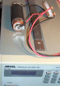
This test was done on the EL1132
Electronic load. It's specified to work down to 2.5 Volts so
the No. 6 Battery Adapter was configured with two series connected
Duracell copper top "D" cells for a nominal 3 volt output.
Fitting a straight line to the measured Volts vs load current over a
range of 0.1 to 3 Amps gives the following equation:
V = -0.3428*I + 2.9734 and R2 = 0.912 where R is a measure of
the fit.
This says the internal battery voltage is 2.9734 and the resistance
of everything in the test setup including the internal resistance of
the battery is 0.3438 Ohms. If all of that resistance was
inside the battery adapter then the Flash Amps (see
below) would be about 8.6. If 1/3 of the resistance was
the battery adapter, 1/3 the wires to the Power Pole connector on
EL1132test wires and 1/3 the test wires from the power pole to
the EL1132 bus bars then the flash amps would be about three time
more or just short of 26 Amps.
The ESR meter shows 0.16 Ohms at the top of the 6-32 terminal screws
and essentially the same reading across the two D cells, so the
resistance of the wiring and connectors is minimal.
The HP 34401 in 4-wire Ohms shows 13 milli ohms for black and 17
milli Ohms for red or a total of 30 milli ohms for all the wires
from the battery holder to the power pole connectors.
Testing just the ring terminal wires to the Power Pole connector
shows 8 milli ohms for the red and 8 milli ohms for the black.
Summary of milli Ohms
EL1132
|
342.8
|
ESR meter
- wires & batt
|
160
|
ESR meter
- just 2 D batt
|
160
|
ESR
- just all wires
|
30
|
HP 34401
- just all wires
|
30
|
HP 34401
- just test wires
|
16
|
So all the wires look like 30 milli Ohms and the two Duracell D
batteries are probably about 130 milli ohms. There's probably
some resistance in the battery holder terminal to battery joint.
Post Mercury Ban Alkaline
The
current version of the No. 6 is no longer a Carbon Zinc, but a
post Mercury ban Alkaline. This type of alkaline cell is the
common type on the shelves of all kinds of stores that sell the
common AAA, AA, C, D and 6 Volt lantern and 9 Volt transistor
radio batteries.
The Zinc Carbon cell uses Amalgamated Zinc which means Zinc that's
been treated with Mercury. The first generation Alkaline
cells also used Amalgamated metal (I forget but it may have been
Zinc). So when Zinc could no longer be used in batteries a
whole new generation of Alkaline batteries was developed.
The bulk of the
patents you see on
any Energizer battery package are related to making a Mercury free
alkaline cell.
The top button, top surface and cylindrical surface is the
positive contact. The center of the bottom is the negative
contact. This is very different than the old Zinc Carbon
where only the button was the positive contact.
This can cause shorts in some applications that were designed for
Zinc Carbon cells, like the
PSR-1 Seismic
Intrusion Detector where the battery clips can cut through
the thin plastic label on a modern battery and short the positive
battery terminal to chassis ground which is the negative terminal.
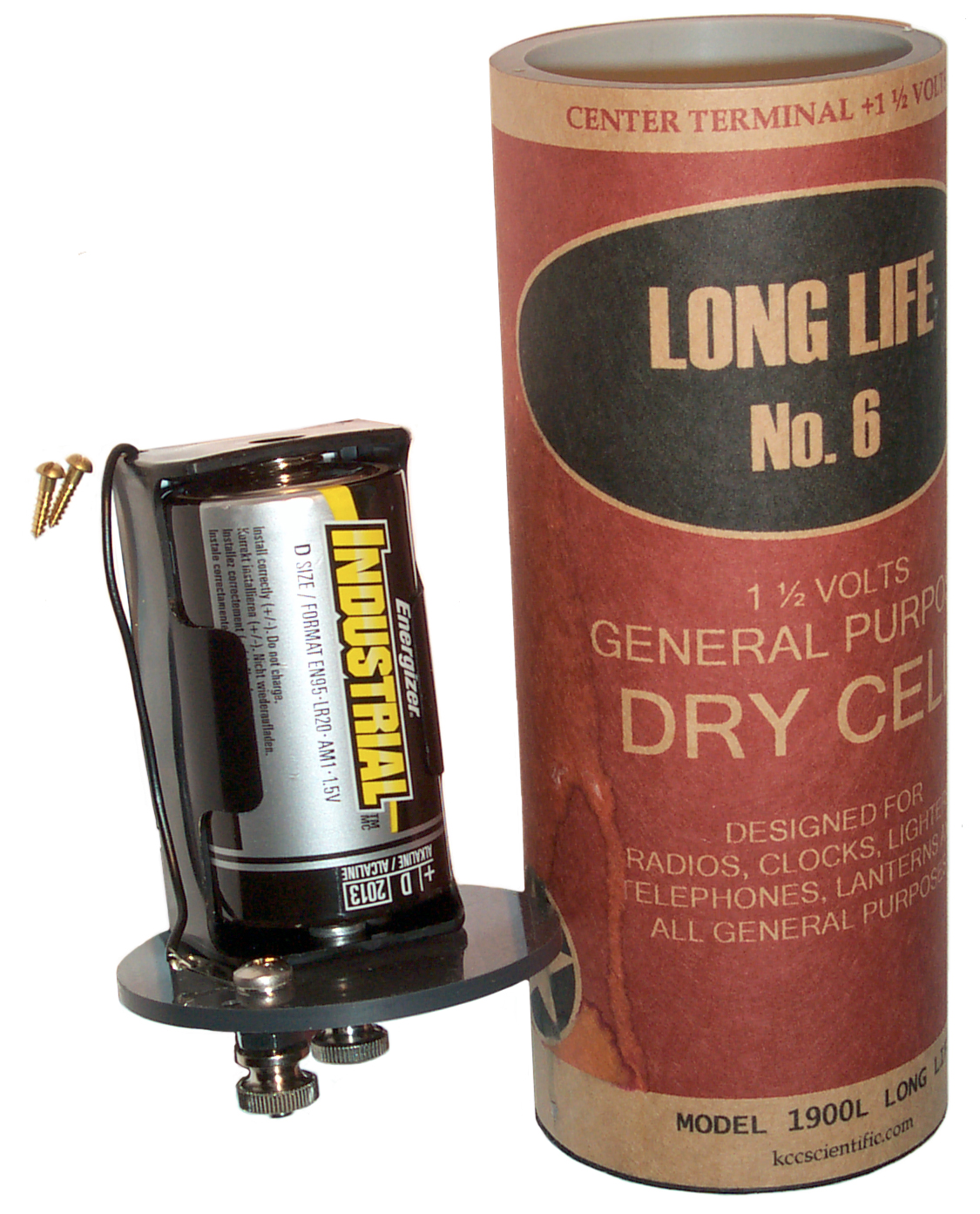
Modern No. 6 Battery
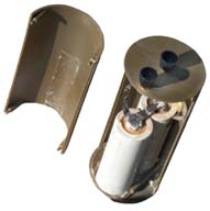
The No. 6 battery
that's being sold today is no longer a single cell that's the same
size as the old No. 6, but instead is a plastic shell that holds a
couple of "F" size modern Alkaline cells connected in
parallel. The reason for connecting them in parallel is two
fold.
First by paralleling a couple of "F" cells the capacity of the
modern No. 6 probably approaches that of the original Zinc Carbon
No. 6.
Second by paralleling a couple of "F" cells the internal
resistance of the modern battery probably approaches that of the
original Zinc Carbon No. 6.
I've been studying a number of products based on electromagnets
like the
Self Winding Clock which was
designed originally (1884 - 1930) for a couple of wet batteries,
and the later clocks (1930 to 1960) were designed to be powered
from two each No. 6 Dry Cells. The Build it Yourself! a Real
Electric
Motor kit was designed to
run from a single No. 6 Dry Cell and I think the
Electro-Magnetic Toy Engine was
designed to run from a couple of No. 6 Dry Cells.
The interesting thing is that the coil resistance for the two
motors is a small fraction of an Ohm. The modern No. 6 has
an internal resistance of 0.1 Ohm and so will power these motors.
Note that the actual motor current is being set by the
battery's resistance and so it's the key specification. But
a "D" cell has 2 to 3 times the internal resistance and so will
not do a very good job. In this case the problem is
not the amp hour capacity but rather the high internal resistance
of the "D" battery.
Notice the plastic shell on the left has an indentation for the
battery. That's because the outside diameter of two "F"
cells side by side is less than 0.1" less than the maximum
diameter of a No. 6 dry cell. So by thinning the plastic on
both sides right next to the cells the overall diameter will meet
specifications. I can not close this unit maybe because it's
old the the batteries are starting to swell? Two "F"
cells side be side are wider than the outside of a 2" PVC pipe.
There are two metal ribbons spot welded to the "F" cells and an
eyelet or tubular rivet type connection to the bottom of the screw
terminal posts. They are 0.005" thick by 1/4" wide and 2
3/4" long, probably nickel. These are probably 6 milli-ohms
each or 12 milli-ohms for both of them.
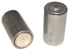
"F" Dry Cell
This cell is the same diameter as the common "D" cell but is 1
inch longer. The "F" dry cell must have been one of the very
early dry cell sizes since a pair of them fit and properly power a
railroad lantern from
prior to 1937. If you know what these were called back in
the early 1900s please
let me know.
This is a modern post Mercury ban
"F" Alkaline dry cell. It has a single layer cardboard
sleeve slipped on to act as insulation between adjacent cells.
The "F" cell has an internal resistance in the 150 to 200 milli
Ohm range, so two in parallel will be about 75 to 100 milli Ohms (
< 0.1 Ohms).
The can is the positive terminal on an F cell and the cap shown at
left on the top is the negative terminal.
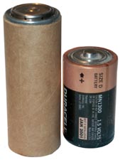
Comparing Modern No. 6 Dry Cell and a 6 Volt
Lantern Battery
This photo gives you the idea that the "F" cells used in the
modern No. 6 Dry Cell are that same as the cells used in a 6 volt
lantern battery.
It would make sense that by combining 4 "F" dry cells in series
you would get a 6 volt battery.
Note "Cell" or "Battery"
A Cell is a single package consisting of the anode and cathode
terminals plus the necessary chemicals to make electricity.
A Battery is made up of a number of cells. This is the
same usage that's applied to an artillery battery made up of a
number of guns or cannons.
So "Cell" is the correct word when talking about "AA" or
"D" or No. 6 and "Battery" when talking about the 6 volt
lantern battery.
Inside the 6 Volt Lantern Battery
After bending back the metal on
the bottom of this Energizer 6 Volt Lantern Battery (model 529)
the following parts are found:
Going clockwise. 4 each "F" cells in cardboard insulating
sleeves. Energizer sells the "F" cell with or without the
cardboard sleeve.
The plastic top with two terminals and one battery to battery
jumper strip.
A cardboard square with two battery to battery jumper strips.
A metal plate with the four corners bent up that pushes on the
plain side of the double jumper strip cardboard.
The bottom square cardboard.
The sheet metal outer case.
Note that there are no welded straps, all the electrical joints
are pressure contacts. Also there is what appears to be
Silicon grease on both ends of all the batteries and on the jumper
strips and terminals. This is an insulator, but would act to
keep air away from the joints thus preventing oxidation.
This may be the same patented
5037566
type that Radio Shack sells as Lube-Gel where there is no
entrapped oxygen.
23 Feb 2008 - needed a 6 volt lantern battery to work on an
Adams-Westlake Railroad lantern
and the above unit is no longer useful that way so got the other
one. It's an Eveready 1209. The 1209 weighs 1 pound
3.7 ounces 19.7 oz). Most of the parts of the 529 weigh 1
pound 15 ounces, probably over 2 pounds (32+ oz) with the
missing parts included. The price and energy content
probably are about proportional to the weight.
My Agilent E3617A bench power supply
rated for 0 to 80 volts at up to 1 Amp will not power the Toy
Engine. The stock 6 volt Lantern battery does power the
engine. The resistance of the two series connected
electro-magnets is about 0.2 Ohms. So connecting a 6 volt
battery might cause a current of 30 Amps to flow, but that can't
happen because the current is limited by the battery. It
turns out the same Energizer battery that I took apart above
demonstrated a resistance of 0.4 Ohms when powering this Toy
engine which along with the resistance of the clip leads limited
the current to about 8.5 Amps (way more than my bench supply can
deliver).
"D" Cell
If the negative end of a "D" cell is held directly on one of the
Toy Engine terminals (to eliminate one clip lead's resistance) and
a clip lead is connected to the other Engine terminal and it's end
held to the "D" cell the engine barley turns over.
Connecting two "D" cells in series runs the Engine at a
respectable rate.
"F" Cell
If the same setup as above is used with an "F" cell the motor is
running at a respectable rate. By holding a couple of "F"
cells in parallel (no cardboard) and using a clip lead to touch
each positive terminal there is not a noticeable
improvement. When two "F" cells are held in series the motor
runs at a faster rate. The spark at the comutator is
brighter and stronger with the "F" cells as compared to the "D"
cells.
The Build it Yourself! a Real Electric Motor kit
The wire that comes with this kit
has a total resistance (for motor electro-magnets and all the hook
up to the No. 6 Dry Cell) of 0.08 Ohms. The instructions for
the motor say it will develop 6,000 RPM from a single No. 6 Dry
Cell. A 1.5 Volt cell with no internal resistance would
deliver just under 19 Amps and a No. 6 with 0.1 Ohms internal
resistance would deliver 8.3 Amps! About the same as the Toy
Engine is drawing. Seeing this is what got me looking hard
at the No. 6 specifications. It's the only Dry battery I've
seen that has specifications on internal resistance (0.1 Ohms at
room temp).
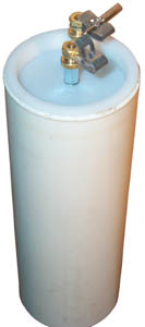
Low Cost Battery Adapter
At the top of this page is shown a
low cost No. 6 Battery Adapter. It's made from 2" PVC pipe.
Construction
of Western Union Clock Battery Packs by
N7CFO.
If you're interested in getting a kit to build this
adapter let me know
I have way more 2" PVC than I need and also have the Rigid
cutter for it.
See it in a
Sweep Second Hand Self
Winding Clock.
Hardware
This is some
terminal hardware consisting of:
* 6-32 Brass screw that will be in the low cost No. 6 Dry Cell
Battery Adapter. They can also be used for Do It Yourself
electrical circuit terminals.
* #6 Brass Nut that can be used to pinch the top of the battery
adapter or for making electrical connections.
* #6 Brass Thumb Nut for making electrical connections. An
option to the thumb nut is the wing nut which allows applying more
torque without resorting to pliers.
* #6 Fahnestock Clip for connecting to wire ends, or better as
shown
* Tip Pin wire termination. These were a very common way of
terminating wires in a way that's much more rugged than just using
the wire itself. Headphones commonly used tip pins.
Western Union clocks (
Self Winding Clock Co,
#2) use these to make it easy for a man
on a ladder to change the No. 6 Dry Cells.
Not shown but also in stock are 8-32 Screws, Nuts, Thumb Nuts and
Brass Washers for both #6 and #8 hardware.
 Teeth
on Pliers
Teeth
on Pliers
On most ordinary pliers there are teeth behind the jaws, i.e.
closer to the hinge pin. For a long time I wondered why they
were included. For example if you use them on pipe or any
smooth round object they do more damage and typically don't grasp
well enough to actually do any good. The answer may be they
are for tightening thumb screws.
The No. 6 Dry Cell is capable of very high currents, (See
Flash Amps below) and a
number of applications use these high currents so good electrical
joints are needed. Finger tightening may not be good enough.
The original Leatherman Tool shown at left has the teeth that look
about like what I remember on everyday pliers. Note that a
homeowner in the late 1800 through the mid 1900s might have a
number of devices that used the No. 6 Dry Cell and so a tool to
tighten them would be a common requirement.
I've read that in Europe Wing Nuts were more popular than Thumb
Nuts because you could get more torque on a wing nut using just
bare hands than was possible with Thumb Nuts.
My local hardware store stocks bronze wing nuts in 6-32 and 8-32,
the two common sizes for No. 6 Dry Cell terminals. Note
bronze offers both good electrical performance and mechanical
strength. The other wing nut sizes are steel.
If you know about the teeth on pliers please
let me know.
Internal Resistance Measurements
By using a slightly modified
Equivalent Series Resistance (ESR) meter
intended for use checking electrolytic capacitors it's possible to
measure the resistance of a live battery.
Energizer white paper on
Battery
Internal Resistance. Mentions "Flash Amps" which is
the current into 0.01 Ohms applied for 200 milli seconds.
Battery
|
Ri Ohms
|
No. 6
Spec
|
0.101 |
| Modern
(old) No. 6 |
0.051 |
F cell
|
0.02 -
0.041
|
D cell3
|
0.06 -
0.09
|
6 volt
lantern
meas on Toy engine
|
0.42
|
Low
Cost No. 6
3 V Battery Adapter
w/ 2 series "D" cells
|
0.36
0.154
|
1.5 V
KCC Single "D"
1900
|
0.22
|
1.5 V
KCC Double "D"
1900-L
|
0.12
|
Seagull
R40
|
0.00
|
Note 1 - The actual resistance for a fresh No. 6 is probably in
the 0.02 to 0.03 Ohm range (i.e. two F cells in parallel plus a
little).
Note 2 - It appears that there is resistance in the 6 volt
lantern battery caused by the two spring contacts, the 3 jumper
bars and the 8 joints between the dry cells and the bars or
terminals that amounts to the bulk of it's resistance. Not
measured using the ESR meter, since it was taken apart prior to
these measurements.
Note 3 - the
Energizer
EN95 "D" cell is specified at 0.15 to 0.3 Ohms.
Note 4 - 10 Oct 2007 measured on low resistance version of low
cost double "D" 3 volt adapter with Duracel batteries. Note
that when two battery adapters are used in series, like in a Self
Winding Clock Co. installation, you end up with twice the
resistance, so in the common case of a single "D" cell in a radio
shack battery holder that may be 0.44 Ohms.
A better way to measure the internal resistance would be to use a
shunt resistor in series with a static load and use a DVM to
measure the voltage drops around the circuit. If a dynamic
load, like a motor is the load then a scope would be needed to
measure the current.
If a 6 Volt Lantern battery is used to power a motor with a
resistance of 0.08 ohms and the battery had 0.4 ohms resistance
and perfect wires are used then about 1 volt will end up across
the motor and the other 5 volts will be in battery loss
resistance. So using a real No. 6 battery or a battery with
an equivalent low resistance will work much more efficiently.
Eveready W.W. II ad for the No. 6 Dry Cell
Flash Amps
Defined as the current into 0.01
Ohms applied for 200 milli seconds. I've been thinking of
how to measure Flash Amps.
A little less than 2 feet of 14 AWG wire has a resistance of 0.01
Ohms, i.e. 10 milli Ohms. So connecting that length of bare
copper wire to a battery will provide the correct load.
Soldering some small stranded wire separated by a little less
length would provide the test leads to a voltmeter so that the
voltage along the wire can be measured. If the leads were
about 12 inches apart the resistance between them would be about
0.005 Ohms and if 20 amps were flowing the voltage would be 100
mv. The HP 34401 when in a fixed range mode and turned down
to 4 digits can make a measurement each millisecond and store
them. It can also be started in this mode from a switch
closure input to TRIG on the rear panel.
17 Nov 2007 - About Pocket Watch Ampere Meters
The early automobiles used "Ignition Batteries" which were
No. 6 Dry Cells. There were two ways
of testing them, you could measure the terminal voltage or the
terminal current. Pocket watch size meters were available as
either a voltmeter, amp meter or a combined meter. A book of
the time recommended that if you could only get one the amp meter
was the most important. The example given was that a dead
battery and a fresh battery read very close to 1.5 volts, maybe
1.5 down to 1.2 volts a very small amount of deflection (3% of
10V) on a pocket watch size analog voltmeter. But the amp
meter would read 10 amps or less for a dead battery and 16 Amps or
more for a good one. Which would be 20% of 30 Amps.
The method was to line up the available No. 6 Dry Cells on the
counter and holding the pocket meter in one hand and the test wire
in the other hand make a firm connection to the battery terminals
(observing polarity) and as soon as the meter needle was steady
remove the meter and remember the reading. I doubt that
there was a "Flash Amps" specification at the time. The spec
was probably made to reflect what was being done.
A loose-leaf book titled "Battery Engineering Data" by the
National Carbon Co., a division of Union Carbide and Carbon Corp.
has data sheets on what may be the full line of Eveready
batteries. At the time the book was written National Carbon
Co. maintained a research lab with equipment to test the RF and
audio characteristics of battery powered radios so that batteries
could be developed to optimally power the radio. There were
different ways of using the "A" and "B" batteries and different
problems associated with either a weak "A" or weak "B" battery in
different designs of radios. When the internal resistance of
the "B" battery is excessive (the battery is going bad) the radio
"motor boats". So far I have not found a date anywhere
in the book, but there is quite a discussion about "B" batteries
made up of flat cells instead of cylindrical cells and references
papers with dates as recent as June 1941.
The book mentions that measuring the terminal current of a battery
does NOT tell you much about how much charge is remaining.
The book about early automobiles was from the late 1800s so by
1941 Measuring Flash Amps was not as popular.
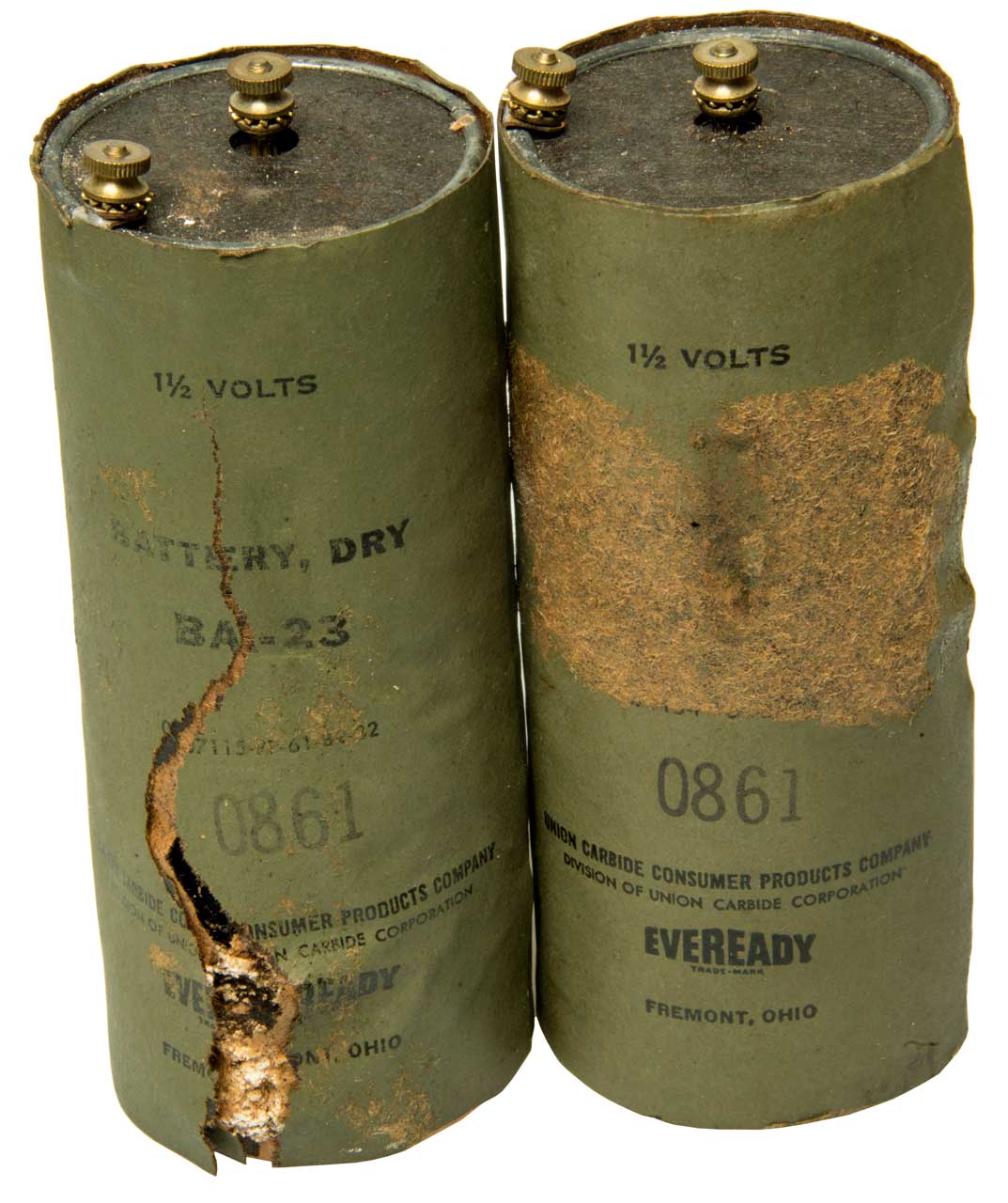
The Battery Engineering Data book shows the terminals on Eveready
No. 6 Dry Cells as 8-32, not the 6-32 that's common on the Chinese
battery. The Brentronics military unit has the proper #8
hardware.
15 Dec 2007
Measured Flash Amps
Using the Conn Tel & Elec Co Inc Flash Amp meter.
|
2 F
cells Parallel
|

|
F
cell
|

|
 |
|
|
|
2 x F
|
Seagull
|
F
|
2 x D
series
(no springs)
|
2D
Series
|
2D
Parallel
|
1900L
2 x D parallel
|
1900L
single D
|
Flash
Amps
|
29
|
26
|
23
|
16
|
14 -
E95
17 MN1300
|
23 -
E95
24 - MN1300
|
11
|
7
|
More Flash Amp Measurements
Made on batteries close at hand, condition unknown
Battery
|
ZTS1
# bars
|
Flash
Amps
|
ZTS
# bars
|
Duracell
MN1300
"D"
|
3
|
4
|
4
|
| Duracell
MN1400
"C" |
3
|
4
|
3
|
Duracell
MN1604
"9 V"
|
5
|
9
|
5
|
Energizer
E91
"AA"
|
4
|
13
|
4
|
Energizer
E95
"D"
|
5
|
13
|
4
|
"
|
5
|
12
|
5
|
"
|
-
|
15
|
3
|
"
|
5
|
12
|
3
|
Energizer
"F"
|
4 2
|
19
|
4 2
|
Radio
Shack 23/872A "AA"
|
5
|
19
|
4
|
Powerizer
(China)
Ni-MH
|
4
|
19
|
4
|
Kirkland
(Costco)
"AA"
|
4
|
8
|
4
|
Note 1 ZTS reado 0 to 5
Note 2 the ZTS is not designed to measure an "F" cell so it's not
surprising that it gives a wrong answer.
Calculations
The open circuit voltage is 1.5
Volts (nominal for a fresh No. 6 Dry Cell or for a single Alkaline
cell like a AA, C, D or F cell).
The voltage across the Flash Amp load resistance of 0.01 Ohm is V
= I * R or V = (FlashAmps) * 0.01.
For example two "F" cells in parallel show Flash Amps of 29 Amps,
then the voltage across the load is 0.29 Volts.
The drop due to the battery internal resistance is 1.5 V - 0.29 V
= 1.21 Volts.
The internal resistance is R = V/I = 1.21 V / 29 A = 0.0417 or
41.7 milli Ohms.
Optimum Power Transfer occurs when the load resistance is equal to
the source resistance. So to get the most power from a
battery the load should have a resistance matched to the batteries
resistance. Primary cells like the No. 6 came in various
versions depending on the load. For example a No. 6 for
telephone use would be designed to supply a small current for a
very long time (a few years). But an ignition battery would
need to supply very high current pulses. So while the
optimum power transfer load works, it also can not be maintained
for very long since the drain is maximized.
Electromagnet Idea
An application would be making an electromagnet where you are
restricted to use only a single "D" cell battery. Since the
Flash Amps for a good "D" cell are around 15 A the voltage across
the load is 0.15 Volts. The drop across the internal resistance is
1.35 V and the internal resistance is about 0.090 or 90 milli
Ohms. So the load should be 90 milli Ohms. If the core
of the electromagnet is a "C" shaped soft iron 1/4" diameter and
is 2" long (with the ends cut off in the same plane so the air gap
to the soft iron keeper is minimized) then the best winding would
be one layer deep and covering all of the "C". Different
wire sizes might be used, but the wire size the results in a 90
milli Ohm resistance (including the leads to the battery) is the
best choice. It turns out that winding more layers results
in lower amp * turns since the resistance goes up faster than the
number of turns, also the copper layer next to the core is
non-magnetic so the area inside the winding is partially
nonmagnetic.
Automating Flash Amp Measurements
The problem is turning on and off the current. Bosch type
automotive relays come in current ratings around 20 to 100 Amps
with coil currents under 200 ma for "12 volt" units. The
contacts are rated around 20 milli ohms for initial resistance and
low currents. The Bosch type relays have quick connect push
on type terminals on one end in a standard pattern and are now
made by many companies and used for many applications. But
may have too much resistance for this test. A number of them
could be connected in parallel. By using a high voltage
driver in series with a power resistor the actuation time can be
made very quick (time = k* L/R).
Relay Data
Brand
|
Model
|
Peak
Amps
|
Contact
Amps
|
Contact
Ohms
|
Coil
Ohms
|
Omron
|
G8JN
|
100
|
35
|
?
|
74
|
Tyco
|
T9A
|
na
|
20
|
0.075
|
144
|
Beuler
|
BU5083B |
-
|
40
|
-
|
80
|
There's what's called "Universal Starter Solenoid. 4 pole, 12
volt" these are SPST N.O. relays used for the starter on small gas
powered garden tractors. Rated for 400 Amps (no more than
0.5 seconds which is fine for this.
Stancor type
120.
There are also the starter solenoids like used on cars.
These are rated 780 Amps intermittent or 85 amps
continuous. Contact resistance is will below 1 milli
ohm.
The IRF 6726 might be able to do this, but the RDSon is around 2.6
milli Ohms or about 26% of the allowed resistance.
Antique Leclanché Wet Battery can produce high Flash Amps
When I tried to measure Flash Amps on the
Leclanché wet
battery a fuse in my
Fluke 87 DMM was burned out.
Two D Cells Series or Parallel
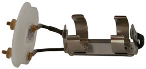
This is a
modified two D cell battery holder. It normally has solder
lugs on the two ends and no electrical connection to the
frame. By installing three terminals, one on each end and one
on the frame the battery holder can be used to combine two D cells
in series or parallel.
The photo at the left shows two D cells in parallel. The
cardboard tube has been removed to make it clearer, but normally
that tube helps keep the batteries from popping out. The
plastic labels have been peeled off the two D cells and they have
been installed with their positive ends touching each other at the
center. These are Energizer E95 Alkaline D cells, but all the
other brands are the same, i.e. the top positive end and the
cylinder are all positive. Only the center of the bottom is
negative. So the black wire is connecting the two negative
terminals together and the frame terminal is the positive terminal.
For a series connection you MUST have the labels on both cells
otherwise one cell will be shorted. Or remove just the bottom
3/4" of label on both cells which allows them to be used for a
parallel connection and for a series connection place the cardboard
over the bare bottom of one of the cells.
The Rayovac MN1300 has slightly more Flash Amp capacity than the
Energizere E95. But two D cells in parallel comes pretty close
to a real No. 6 Dry Cell for Flash Amp capacity.
This would be a handy way for school classrooms to use D size Dry
Cell batteries for electrical experiments.
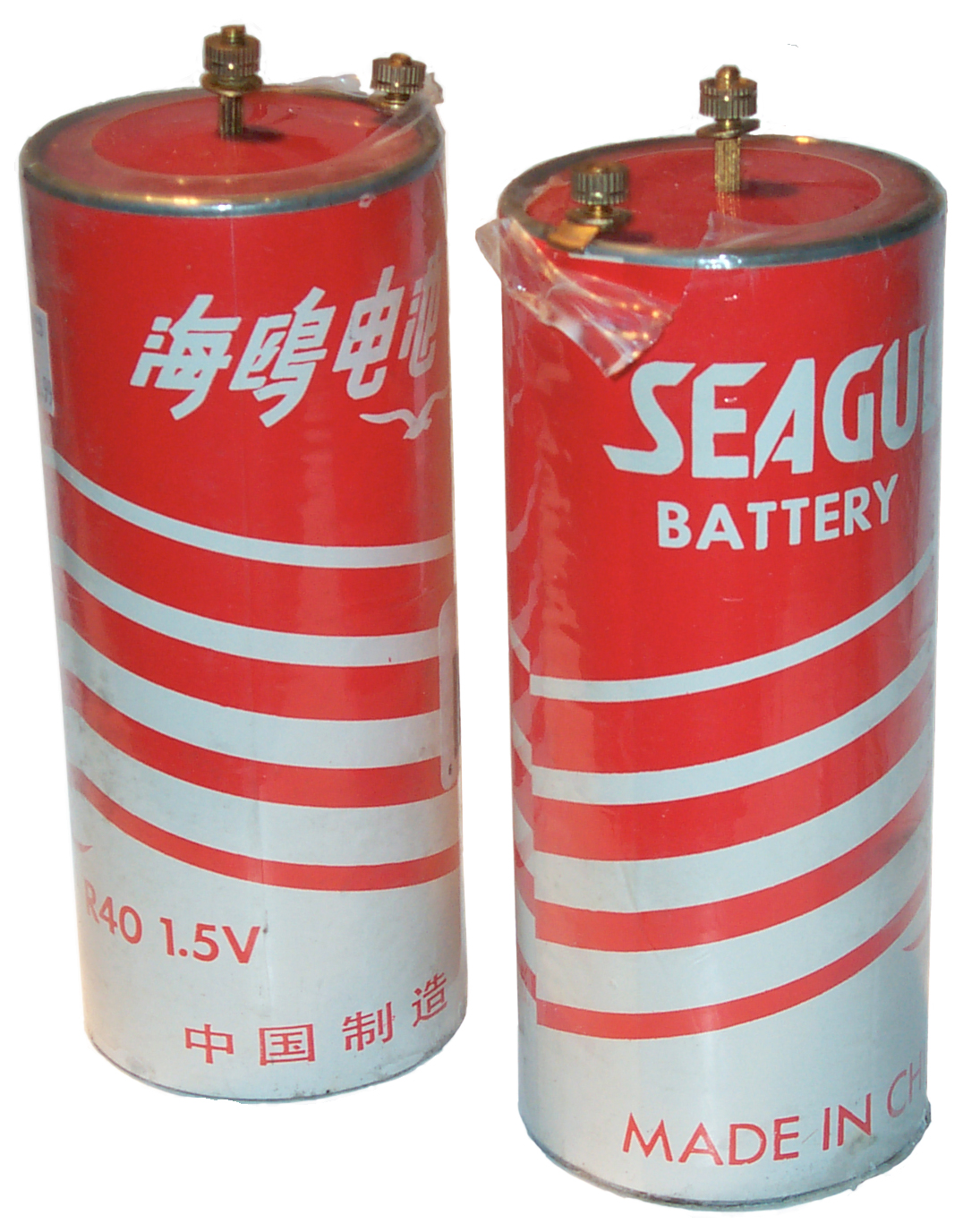
Seagull R40 Batteries

I ordered these
from my local Interstate Battery store as their
Dry1725
expecting it to be made like the Energizer EN6 or military BA-23
using two "F" cells. But it's a real No. 6. They weigh
28.5 oz a lot more than the 16.4 oz for the plastic two "F"
type.
I tried to measure their internal resistance with the modified ESR
meter, but it reads ZERO.
Joseph Henry was the first person to
make what today we call an
electro-magnet
which made the DC motor/generator possible. The unit of
inductance is named Henry after him. His coils were
optimized to use a single wet cell or a small number of
cells. The tests I've done on 1 liter type
Leclanché Cells indicates that they
have very low internal resistance. Henry came up with the
idea of winding multiple coils on a common soft iron core then
connecting them in parallel to a single wet cell. Many of
the electro-magnets he made in the 1900s use large diameter wire
and are intended for low high current use. Henry was the
first
secretary
of the
Smithsonian Institute.
I'm trying to determine if Henry was the first to use insulated
wire for an electro-magnet. Schweigger's (
Wiki)
galvonometer multiplier used bare wire and it may be that
Sturgeon's (
Wiki)
electromagnet was wound on an insulated (maybe just a paper wrap)
horseshoe rather than by using insulation on the wire. I
think Henry used his wife's spinning wheel to wrap silk on "bell
wire" (copper wire used to ring servant's bells in large houses my
mechanical movement, not electricity). By insulating the
wire powerful electromagnets can be made.
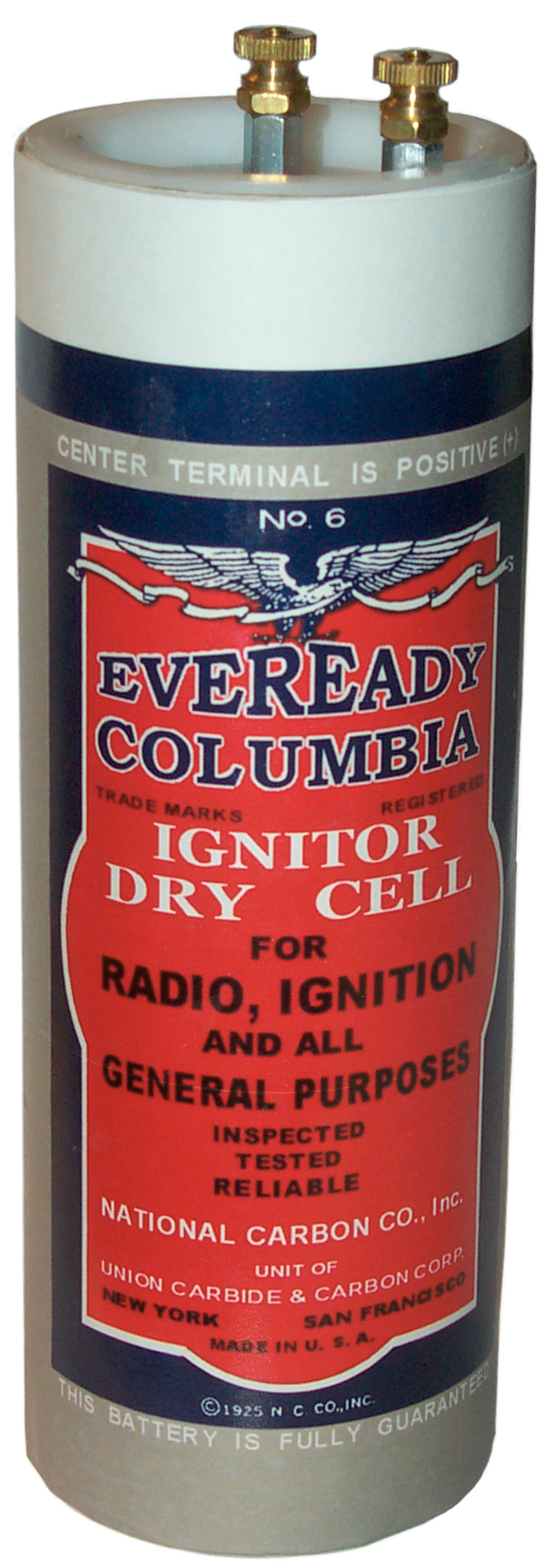
Applications
The first application was for
ignition of explosive engines. The 1893 the Columbia No. 6
had a rectangular center post and was labeled as an ignition
battery. They were shortly thereafter used in
Lanterns as a more user-friendly
source of power than lead acid storage batteries. The early
telephones (
patents,
phones) used what's now called local
battery operation where each phone had it's own battery and the
No. 6 Dry Cell was used in a large number of phones to replace
wet cells.
Patents
The key patents were:
G. L. Leclanché Patents for a wet
battery that does not use acid for the electrolyte 1866, 1867 for
key patents, more later.
Columbia Ignition No. 6 Dry Cell made by National Carbon Co. shows
a patent date of April 11, 1893. The only patent issued on
that date applicable to the No. 6 Dry Cell is:
495306
Galvanic Battery, C.J. Coleman, Apr 11 1893,
429/133 ;
429/249 -
Meter
The Pocket Amp meter was the
standard way to check batteries in the early 1900s. While
the literature mentions testing No. 6 Dry Cells with the amp
meter, I think it was used on any battery. Note since it's
essentially a short it can be applied to any battery to measure
it's ability to produce current. Probably not a good idea
to connect to a lead acid car type battery where the current
would be way over the 35 Amps full scale these meters will
measure, but fine for all dry cell batteries like used in flash
lights, radios, and in the ignition circuit of engines.
327908
Electrical Measuring Instrument, E. Weston (U.S. Electric Lighting
Co), Oct 6 1885,
324/93 ;
324/144 - maybe
the first moving coil meter at least the oldest patent in class
324/144
334145
Electrical Indicator, E. Weston (U.S. Electric Lighting Co),-
under glass dome
340399
Electrical Indicator, E. Weston (U.S. Electric Lighting Co),
------------ Edward Weston has a bunch of meter
patents------------
619679
Galvanometer, A.A. Dittmar, Feb 14, 1899, 324/147 - pocket watch
size
686561
Battery-Gauge, Charles R. Underhill (1/2 to Varley Duplex Magnet
Co), Nov 12, 1901, 324/144 - pocket watch case
incuudes two five Ohm
resistors and allows reading the current through 10 Ohms and 5
Ohms to then compute the internal resistance of the battery.
839637 Pocket
Ammeter Dec 25 1906, 324/144 - 270 degree pointer movement, pocket
watch case
854709
Electrical Measuring Instrument, J. Abrahamson, May 28 1907,
324/146 - slotted dial to pass pointer, pocket watch case
1148218
Battery Tester, Emerson L. Clark, National Carbon Co. Jul 27,
1915,
324/145 ; 324/72.5 - a cylindrical flash amp tester
with a micrometer like calibration
1205343
Apparatus for Testing Dry Cells, J.H. Goodwin, F.A. Adamski, Nov
21 1916, - 4 minutes each hour for 10 hours/day for 6 days a week
for . . . .
1262000
Battery-meter,
William
Anthony, 1918-04-09, - iron vane type
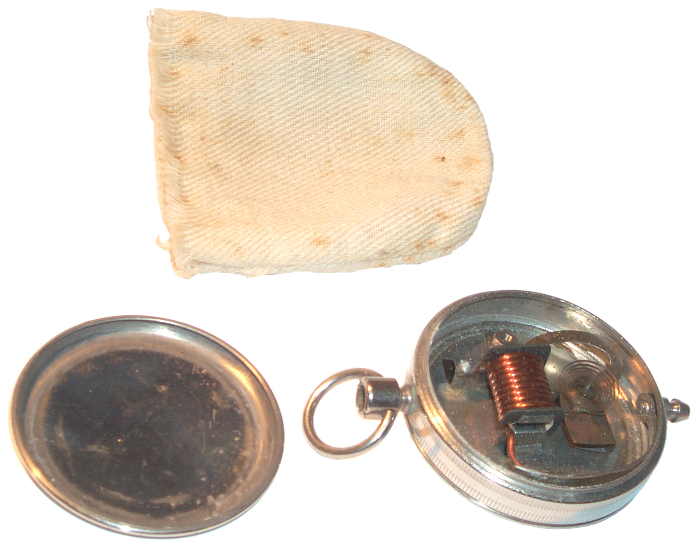
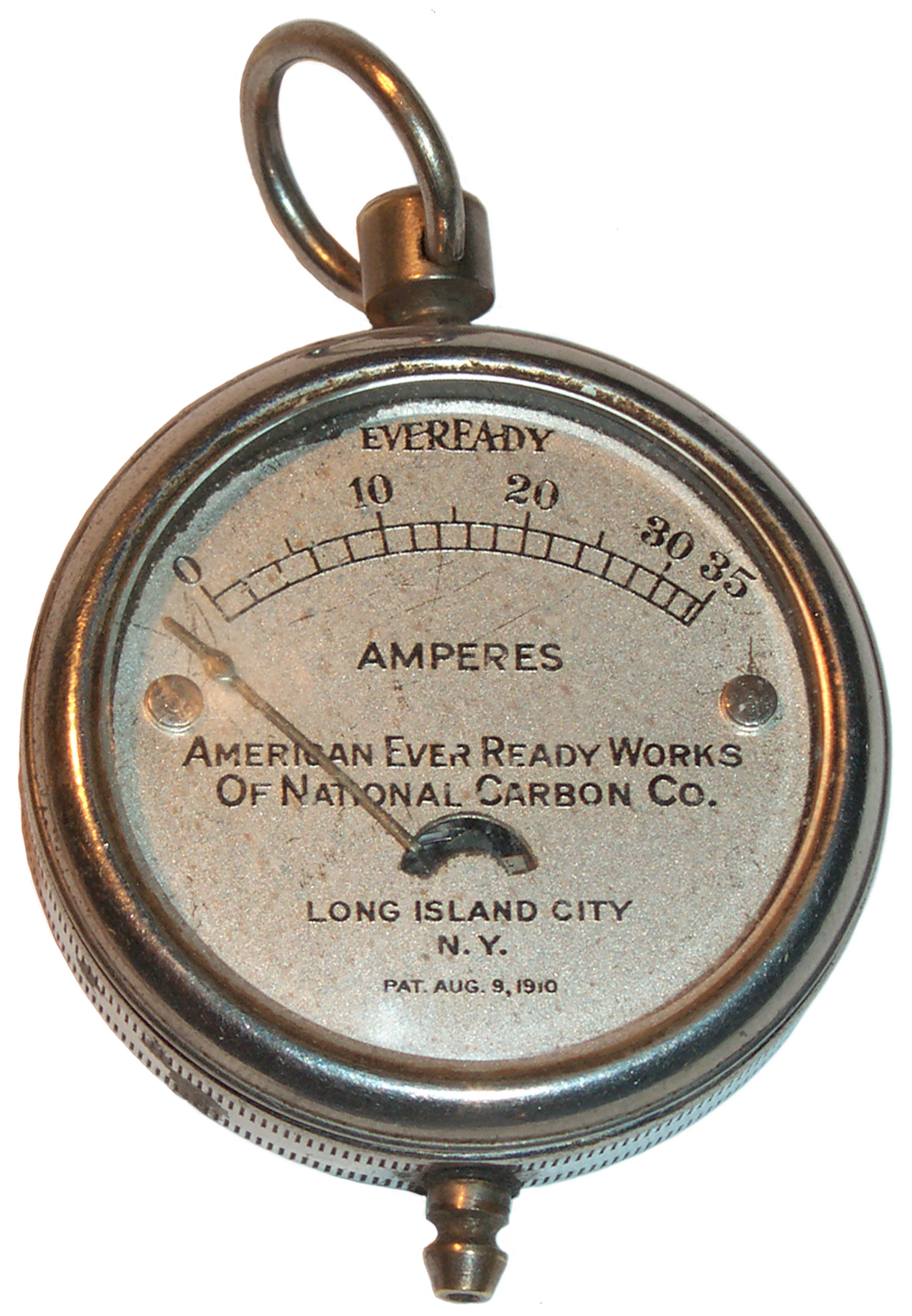
Eveready Pocket Amp Meter
966421
Portable Electrical Measuring Instrument, W.E. Beede (American
Ever Ready Co ), August 9, 1910, 324/145 - moving vane gets pulled
into coil
0 to 35 Amp scale.
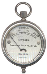 |
The crown has a socket for
a short wire that's missing. The meter works, but
does not give the same reading as the Conn Tel & Elec
meter. It might be possible to make the plug for the
crown and the cable to go with it.
See the Flashlight web page for a photo of this meter with
a few pocket flash lights, all Eveready barnded.
1906 to 1909 Made by National Inst Co, Hartford, Conn
|
 |
Cloth pouch for Pocket Flash Amp meter.
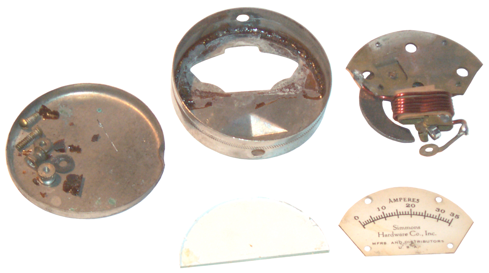
This is wha't called a moving vane meter. The
scickle shaped vane is pulled into the 8 turn coil more
and more as the current increases. The wire is
0.051" dia or 16 AWG which has 3.1845 Ohms/Kft or 3.1845
Milli Ohms per foot. For 10" of wire that's about
2.65 milli Ohms. But the total load resistance of
the test will also include the resistance of the:
- top solder joint
- metal case from the top solder joint to the top
terminal post
- joint between case and top terminal post (on this
meter it's very high since the post can easily be
turned)
- top terminal post
- joint to test lead plug, solder joint, test lead,
solder joint, terminal, contact to battery post
- bottom solder joint
- strap from bottom solder joint to hole for bottom
terminal post
- joint between strap and bottom terminal
- bottom terminal & contact to battery post
|
|
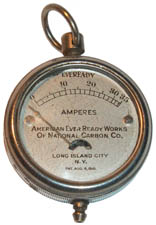
1914 This may be the newest
of the pocket amp meters.
|
1012209
Testing Apparatus,Union Switch & Signal, Dec 19, 1911,
324/418
; 324/157; 338/148; 338/176 - more the size of a flashlight
1184536
Portable Electrical Measuring Instrument, May 23, 1916,
324/145
; 336/130; 336/223; 336/45 - coil a sheet metal stamping, window
to see current
1199829
Battery-Meter, Walter M. Scott,
Sterling Manufacturing Co, Oct 3, 1916,
324/115
; 324/146; 324/149 - frame saves parts and labor
The dial face reads: Simmons Hardware Co., Inc., Mfrs and
Distributors, U.S.A. The
eBay
auction shows the meter face and the pointer is a little
above zero. When the meter arrived in a ReadyPost Photo
Document Mailer with no padding the meter needle and other parts
were loose inside the case. Terminal 3 was loose in the
mailer and external insulator 23 was missing, although shown in
the eBay photo. Very poor packaging.
The meter movement is about 4 milli Ohms, but the wire is 230
milli Ohms. Yet the wire (patent drawing # 4) appears
visually to be OK, it has a serious problem.
Using this wire, not the wire that came with the Conn Tel &
Elec meter the Seagull battery read 15 Amps and the crimp terminal
got very hot.
After doing this the wire resistance is 55 milli Ohms. A
close look at the crimp shows that is was made with the insulation
still on the wire! This appears to be a regular closed
barrel ring tongue terminal, although there is a gap in the barrel
with the insulation showing the full length.
1223306
Electrical Measuring Instrument, 324/146
1315816
Pocket Flash-light Battery and Bulb Tester, R.E. Cole, Sep 9,
1919,
324/444 - uses bulbs and ammeter
1337160
Battery Tester, G.H. Riebeth, Apr 13 1920,
324/437 ;
324/537; 429/90 - connects to the top of a No. 6 dry cell and
reads the current 0 - 30 Amps
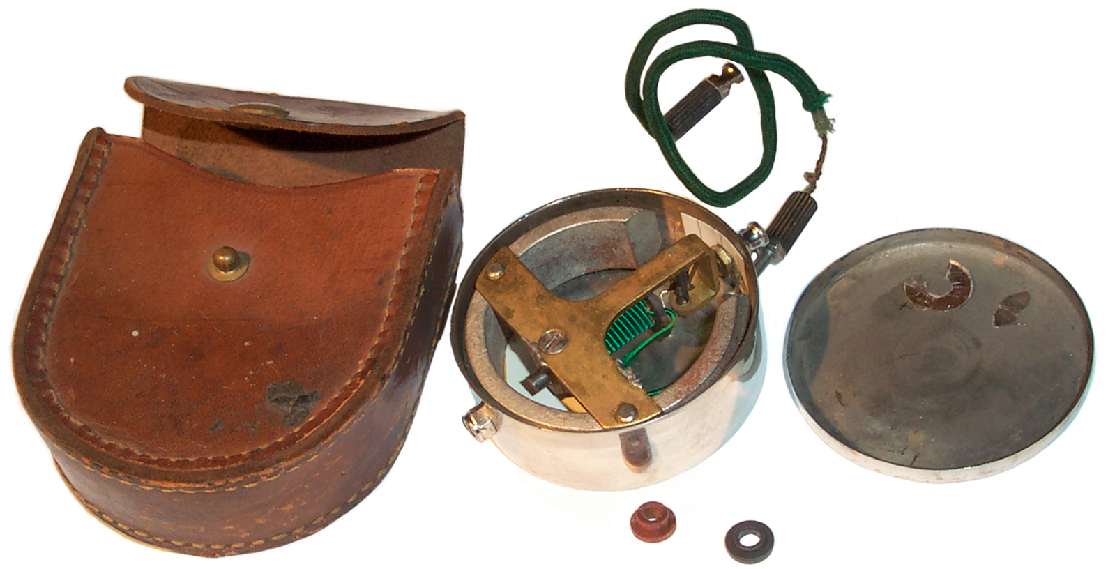
Conn Tel & Elec Flash Amp Meter
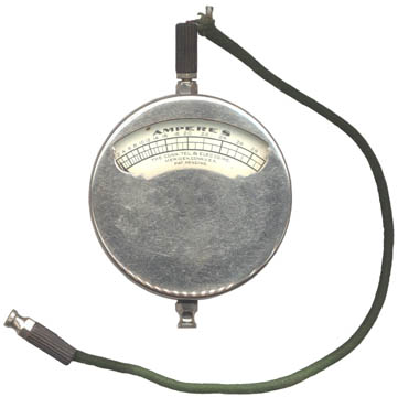
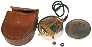
15 Dec 2007 This meter arrived DOA.
Once the back was off (Kroil helped when prying the back) the
problem was that a Mica washer was used between the terminal lug
on the end of the green wire and the case as an insulator.
The terminal that screws into the outside has what amounts to a
shoulder washer to keep it from touching the case. Mica is
fragile and the washer had broken. It's inside the back
cover on the right. I just cut a small square of 3 x
5" card and used that on the inside as an insulator as a temporary
fix and the meter is now working.
The connector at the top on the green wire and the connector at
the bottom of the meter have cup shaped ends. Just the thing
for putting on the threaded terminal posts of a No. 6 Dry Cell.
The wire connects to the meter using a tappered pin on the wire
that fits a tappered socket on the top meter terminal. It
works like the Morse Tapper used in machine tools like lathes and
drill presses. You push and turn the connector and it makes
an extreamly good joint.
The meter is about 8 milli Ohms and the wire 9 milli Ohms and when
both are measured it's about 15 milli Ohms.
Measuring from the wire connector to the meter connector when they
are mated reads zero =/- 1 milli Ohm. It's a very low
resistance type of connection, far better than a PP15 series Power
Pole.
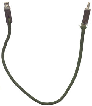
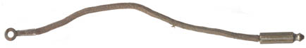
The
negative battery terminal connector on the test lead shown at the
left is the same as the batery positive terminal connector on the
bottom of the meter. They have a hollow pocket that allows
holding the connector on top of the threaded terminal on the No. 6
Dry Cell.
The wire measures about 10 milli Ohms and the meter is about 8.2
milli Ohms.
But the wire which appears to be stranded 18 AWG has broken
strands. 18 AWG is specified at 6.6 milli ohms per foot and
so 9½ inches should be about 5.2 milli Ohms so it's twice as high
as it should be.
The interesting end is the tapered pin. It fits a tapered
socket on the top of the meter. To make the connection you
press and turn the pin. The resulting connection has
extreamly low resistance. To remove just pull and turn.
The two round parts are some sample shoulder washers that have a
hole about the correct size to replace the broken mica washer, but
I'm liking the card stock more and more.
Just grabbing a number of cells that are nearby shows Flash Amps
when making the connection directly to the battery (no battery
holder) as shown:
D cell: 4 to 15 Amps
C cell: 6 Amps
AA cell: 18 Amps
9 Volt: 10 Amps
18650
1: pegs the needle > 30 Amps
LIR123A
1: 28 Amps and going down scale
quickly
Note 1 When testing these batteries the contact was made and
released in less than a second. The needle does not peg so
much as hits the peg at full scale and bounced back and forth.
The readings from different batteries varies a lot more than a
voltage reading. Since the internal resistance of a battery
is an indicator of it's state of charge the Flash Amp reading may
have more than a passing relationship to State Of Charge.
See more Flash Amps data
above measured with
this meter.
Dual Range Pocket Voltmeter
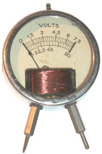
This
is
a
Voltmeter for checking what were then common battery voltages
which were: 1.5, 3, 4.5 and 6 on the low range and 22.5, 45 and 90
on the high range. Stamped into the case at the bottom
adjacent to the left probe is 90 and adjacent to the right probe
is 7.7. Half way between them is the ground schematic
symbol, meaning a test lead from the top threaded terminal is the
ground connection.
The low range is about 1,000 Ohms per Volt and the high range is
about 10,000 Ohms per Volt.
The readings on the low range are way off, yet the high range is
quite close.
Meter
|
1.5
|
3
|
4.5
|
6
|
7.5
|
22.5
|
45
|
Actual
|
1.33
|
2.48
|
3.81
|
5.12
|
6.54
|
21.4
|
42.2
|
Error %
|
-13
|
-21
|
-18
|
-17
|
-15
|
-5
|
-7
|
After removing the two screws on the back the back cover does not
want to come off. Applied a very small amount of Kroil and
will check again over the next few days. Maybe the reason
for the large error on the low range can be seen.
Note if the error was the same when this no name meter was new
it's easy to see why the pocket amp meters were much preferable to
a voltmeter. The error is close to the difference between a
full battery and a dead one.
|
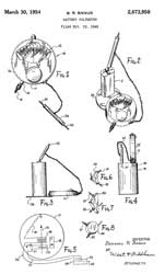
2673958
Battery voltmeter, Bernard
R Banus, Sterling
Mfg Co, 1954-03-30, - for testing "A" or "B"
batteries. Uses two different coils one for "A"
batteries and another for "B" batteries.
This may or may not be the patent for the Dual Range
Pocket Voltmeter.
|
Yankee Volt_Ammeter
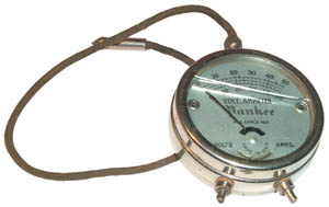
0 to 50 Volts
and 0 to 50 Amps. Marked pat. appld for, made in
U.S.A. At the bottom there's a circular cutout in the
dial and what looks like a notch where a stylus could be inserted
to set the zero. Both Volts and Amps are operational,
although like the meter above far from what today would be called
calibrated. The glass is broken so needs to be
replaced. The ground lead is attached to the meter and so is
here. The only other ground lead is the meter that came in a
leather case. The lesson seems to be if there's no place to
store an accessory, even a critical one, it will get separated and
that means lost.
Links
There are a couple of people who
make No. 6 battery adapters that make use of "D" cell
batteries. There are thumb screw or
Fahnestock Clip terminals.
Back to Brooke's PRC68, Products for Sale, Battery,
Mil Battery Table, Battery Patents, Flashlights, Leclanché Wet Battery Telegraph, Leclanché
Battery, Electronics, Military Radio, Personal
Home page
[an error occurred while processing this directive] page created on 3 Sep
2007


 This is
based on the same concept of using test caps for the ends and PVC
pipe for the tube. I've found a combination of fittings that
allows the user to choose either Fahnestock Clips or thumb screws
(maybe also an option for Wing Nuts which were commonly used in
Europe then you don't need pliers to tighten the thumb nuts.
Ever wonder what those "teeth" on pliers were
for?). Note if you add Fahnestock Clips under the thumb nuts
then you can not depress the clip far enough to insert a tip
pin. Notice there's a tip pin installed in prototype 2.
This is
based on the same concept of using test caps for the ends and PVC
pipe for the tube. I've found a combination of fittings that
allows the user to choose either Fahnestock Clips or thumb screws
(maybe also an option for Wing Nuts which were commonly used in
Europe then you don't need pliers to tighten the thumb nuts.
Ever wonder what those "teeth" on pliers were
for?). Note if you add Fahnestock Clips under the thumb nuts
then you can not depress the clip far enough to insert a tip
pin. Notice there's a tip pin installed in prototype 2.
 The
current version of the No. 6 is no longer a Carbon Zinc, but a
post Mercury ban Alkaline. This type of alkaline cell is the
common type on the shelves of all kinds of stores that sell the
common AAA, AA, C, D and 6 Volt lantern and 9 Volt transistor
radio batteries.
The
current version of the No. 6 is no longer a Carbon Zinc, but a
post Mercury ban Alkaline. This type of alkaline cell is the
common type on the shelves of all kinds of stores that sell the
common AAA, AA, C, D and 6 Volt lantern and 9 Volt transistor
radio batteries. The No. 6 battery
that's being sold today is no longer a single cell that's the same
size as the old No. 6, but instead is a plastic shell that holds a
couple of "F" size modern Alkaline cells connected in
parallel. The reason for connecting them in parallel is two
fold.
The No. 6 battery
that's being sold today is no longer a single cell that's the same
size as the old No. 6, but instead is a plastic shell that holds a
couple of "F" size modern Alkaline cells connected in
parallel. The reason for connecting them in parallel is two
fold. 
 After bending back the metal on
the bottom of this Energizer 6 Volt Lantern Battery (model 529)
the following parts are found:
After bending back the metal on
the bottom of this Energizer 6 Volt Lantern Battery (model 529)
the following parts are found: This is some terminal hardware consisting of:
 Teeth
on Pliers
Teeth
on Pliers

 I ordered these
from my local Interstate Battery store as their Dry1725
expecting it to be made like the Energizer EN6 or military BA-23
using two "F" cells. But it's a real No. 6. They weigh
28.5 oz a lot more than the 16.4 oz for the plastic two "F"
type.
I ordered these
from my local Interstate Battery store as their Dry1725
expecting it to be made like the Energizer EN6 or military BA-23
using two "F" cells. But it's a real No. 6. They weigh
28.5 oz a lot more than the 16.4 oz for the plastic two "F"
type.


 15 Dec 2007 This meter arrived DOA.
Once the back was off (Kroil helped when prying the back) the
problem was that a Mica washer was used between the terminal lug
on the end of the green wire and the case as an insulator.
The terminal that screws into the outside has what amounts to a
shoulder washer to keep it from touching the case. Mica is
fragile and the washer had broken. It's inside the back
cover on the right. I just cut a small square of 3 x
5" card and used that on the inside as an insulator as a temporary
fix and the meter is now working.
15 Dec 2007 This meter arrived DOA.
Once the back was off (Kroil helped when prying the back) the
problem was that a Mica washer was used between the terminal lug
on the end of the green wire and the case as an insulator.
The terminal that screws into the outside has what amounts to a
shoulder washer to keep it from touching the case. Mica is
fragile and the washer had broken. It's inside the back
cover on the right. I just cut a small square of 3 x
5" card and used that on the inside as an insulator as a temporary
fix and the meter is now working. The
negative battery terminal connector on the test lead shown at the
left is the same as the batery positive terminal connector on the
bottom of the meter. They have a hollow pocket that allows
holding the connector on top of the threaded terminal on the No. 6
Dry Cell.
The
negative battery terminal connector on the test lead shown at the
left is the same as the batery positive terminal connector on the
bottom of the meter. They have a hollow pocket that allows
holding the connector on top of the threaded terminal on the No. 6
Dry Cell. This
is
a
Voltmeter for checking what were then common battery voltages
which were: 1.5, 3, 4.5 and 6 on the low range and 22.5, 45 and 90
on the high range. Stamped into the case at the bottom
adjacent to the left probe is 90 and adjacent to the right probe
is 7.7. Half way between them is the ground schematic
symbol, meaning a test lead from the top threaded terminal is the
ground connection.
This
is
a
Voltmeter for checking what were then common battery voltages
which were: 1.5, 3, 4.5 and 6 on the low range and 22.5, 45 and 90
on the high range. Stamped into the case at the bottom
adjacent to the left probe is 90 and adjacent to the right probe
is 7.7. Half way between them is the ground schematic
symbol, meaning a test lead from the top threaded terminal is the
ground connection.
 0 to 50 Volts
and 0 to 50 Amps. Marked pat. appld for, made in
U.S.A. At the bottom there's a circular cutout in the
dial and what looks like a notch where a stylus could be inserted
to set the zero. Both Volts and Amps are operational,
although like the meter above far from what today would be called
calibrated. The glass is broken so needs to be
replaced. The ground lead is attached to the meter and so is
here. The only other ground lead is the meter that came in a
leather case. The lesson seems to be if there's no place to
store an accessory, even a critical one, it will get separated and
that means lost.
0 to 50 Volts
and 0 to 50 Amps. Marked pat. appld for, made in
U.S.A. At the bottom there's a circular cutout in the
dial and what looks like a notch where a stylus could be inserted
to set the zero. Both Volts and Amps are operational,
although like the meter above far from what today would be called
calibrated. The glass is broken so needs to be
replaced. The ground lead is attached to the meter and so is
here. The only other ground lead is the meter that came in a
leather case. The lesson seems to be if there's no place to
store an accessory, even a critical one, it will get separated and
that means lost.