Teletype Monopulse Printer
© Brooke Clarke 2009
Background
Also known as the Teletype Model 36.
I've been told that these were used
inside factories ( located on the same power gird as the
transmitter) for internal
communications. They work using a type wheel (missing from
this
one - If you have one or know about them please
let me know).
The name comes from the idea that a single pulse defines each
character, rather than using 5 or more pulses for each
character.
The width of the pulse determines which character gets
printed.
The key to this type of system is getting the transmitter and
receiver
synchronized.
Description
|
TELETYPE MODEL 36
(MONOPULSE) TAPE PRINTER SET
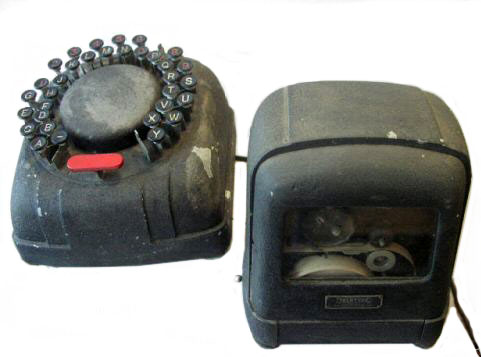
		The Teletype Model 36 Monopulse printer is a simplified printing telegraph device designed to supplement conventional Teletype apparatus in local circuit applications where printed message service is desired but where the traffic is not sufficient to justify the installation of standard Teletype equipment.  With Monopulse equipment, letters, figures and the
dash symbol (-) are alphabetically arranged. Selection is obtained through variations in the length of single pulse signals originating with the keyboard transmitting station. The set is particularly adapted for economical printed intercommunication services in offices, stores, banks, railway stations, factories warehouses, yards, etc., where all stations will be located
within a limited radius and have access to the same 115 volt 60 cycle power source.  Monopulse equipment is not adapted for operation with other Teletype apparatus, and because of this and other limitations is recommended for local message service only. For general communications service over extended circuits see Teletype Model 14 and Model 15 printers.
______________________________________________________
YEARS PRODUCED & QUANTITY:   1942-1951   149 units
PRIMARY CUSTOMERS:   Bell, General
CLASSIFICATION CODE:   HP (Printer)  HK (Keyboard)
MUSEUM CODE:   2C-24
TECHNICAL BULLETINS & SPECS:   16, D1-1
PHOTO NO(S):   690505-11
PATENTS:
LIBRARY REFERENCES:  [ATT - Teletype Corporation; "Museum Equipment"; book 1, p33]
|
Printer Size & Weight
If you are used to TTY machines, this is much smaller! It's
6" wide, 5" deep and 6" tall.
Weighs 7.5 pounds, but the line filter (or similar component is
missing) maybe 8 pounds total.
Paper Tape
Width: 3/8" core I.D.:
7/16"
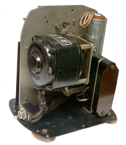
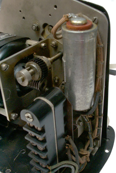
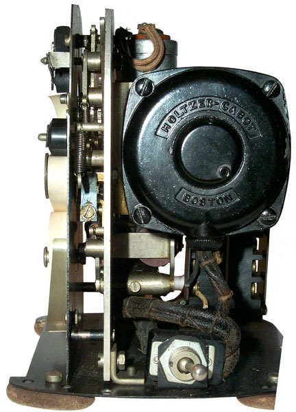
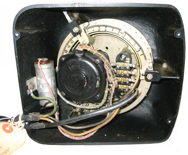
Electric Motor
A.C. Synchronous Motor, Type RWC 2510, Volts: 110, Cycles: 60,
R.P.M.
1800. No. 1015237, Watts: 9, Torque: 0.3 In. Oz., The
Holtzer-Cabot
Electric Co., Boston, Mass, U.S.A.
The worm gear reduces the speed by 15X i.e. 1800 RPM / 15 = 120
RPM or 8.333 ms per character.
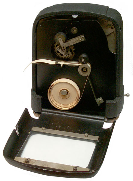
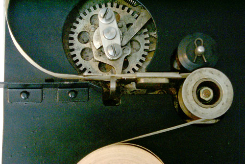
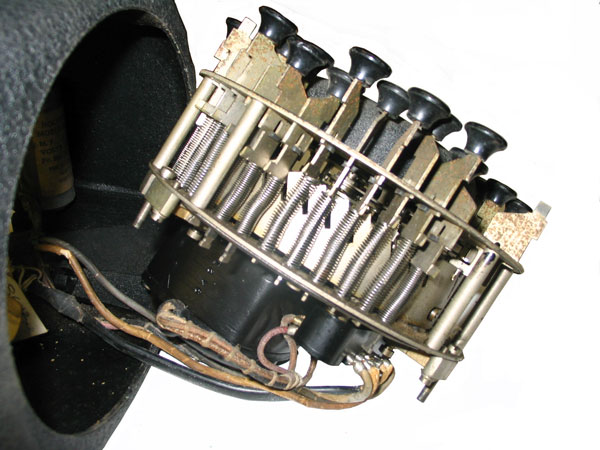
Type Wheel
Mounts using two screws about 9/16" c-c. The hole in the
panel
behind the type wheel is 1.45" dia. There is a print hammer
under
the paper tape that snaps up to print the character.
Solenoid
There is a solenoid on the back side related to driving the print
hammer.
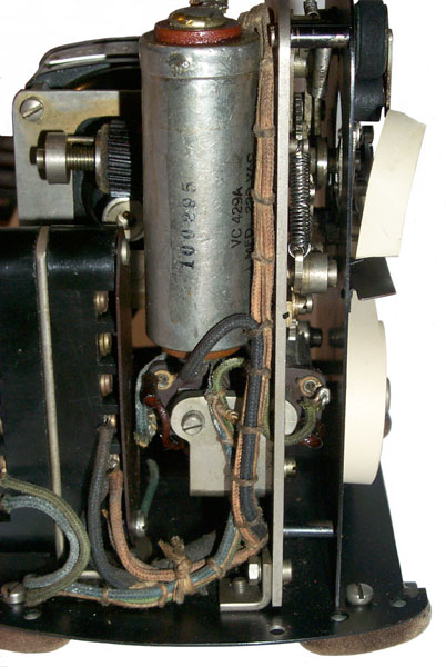
Big Cap
Marked: 100295, VC429A, 1 MFD 220 VAC
Related to the motor.
Missing Component
Most likely an A.C. power line filter, see Electrical below.
If you know what's missing please
let
me know.
Electrical
The rear terminal strip is NOT connected to the front terminal
strip.
Rear Terminal Strip (Motor)
The bottom three terminals are used. The On-Off switch
connects
to the upper two terminals and the motor to the lower two
terminals. The cut wires are colored:
Black - upper terminal - A.C. Line
White - lower terminal - A.C. Line
Green - connects to the terminal strip mounting screw - chassis
ground
The missing component may be a power line filter??
Front Terminal Strip (Solenoid)
Only the bottom two terminals are used. They go to the
solenoid
which has it's two coils wired in series. Resistance is
204
Ohms. 20 Volts (100 ma) will operate the solenoid.
Operation Description
[from "History of Telegraphy from
the Teletype Museum"; Ransom D. Slayton, Consultant;1983]
"203. There was always the push to develop lower cost units for simpler systems. One such system was the Model 36 Monopulse.
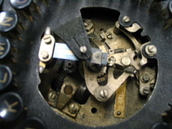
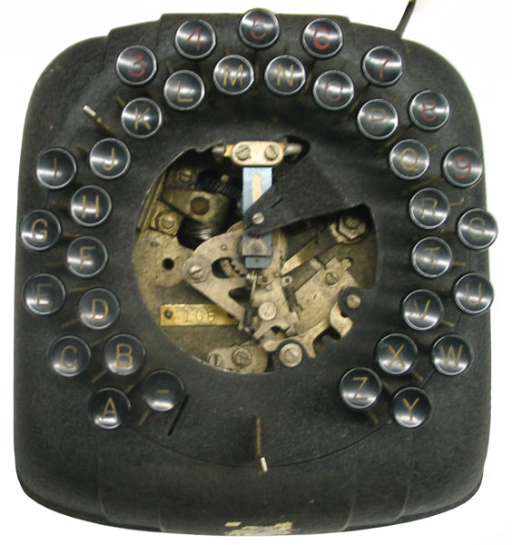
"204. This operated much like some early stock tickers, with the line signal being an OPEN interval during which sending and receiving devices rotated until the proper point was reached for printing the desired character. the Keyboard, at the left here, had its Keys mounted in a circle, which was non-standard and took a bit of training by the operator. The sending contact was opened by depressing a key, and remained open until the selecting arm reached that key after leaving its rest of STOP position.
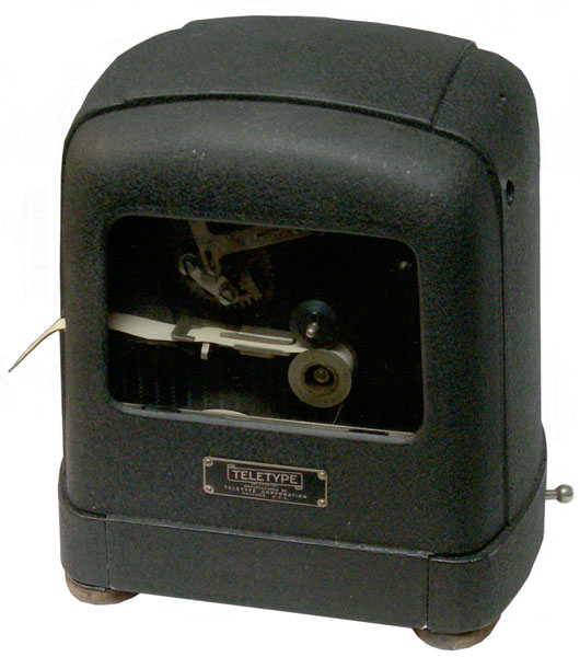
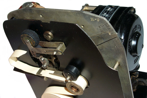
"205. Meanwhile, the selecting arm at the receiving Printer was similarly seeking the printing point. When the line closed, it was there, so the printing hammer struck the rotating type wheel, printing the character. The Printer type wheel was inked, much as the old BLUE and GREEN code printers had been. The inking roller can be seen at the top of the printer, with the type wheel under it. then comes the printing tape, the supply roll of which is at the bottom. The printing hammer is just under the tape and print wheel, and moves upward to cause printing. The system was very simple and therefore low cost, but only a limited number were made. "
The early Baudot teleprinters held the selector with an
electromagnet
and at the start of a character released it allowing the selector
to
rotate. It makes sense that this printer used a very similar
technique, except here the circle is divided into 26 letters and 9
numbers (letter O doubles as the number zero). The time when
there's no current determines which character is going to be
printed. When the line is again connected the electromagnet
is
activated (causing the print hammer to strike) and when the
transmitter
and printer get to top dead center the rotation stops, ready for
the
next character.
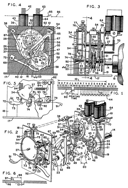
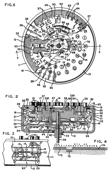
Patents
Receiver
2249040
Printing Telegraph Apparatus, Louis M. Potts (Teletype Corp), Jul
15, 1941,
178/35 -
 2367427
Telegraph Transmission System, Louis M. Potts (Teletype Corp), Jan
16 1945,
178/17A ; 178/17R -
Transmitter
2173147
Telegraph Transmitter, Walter J. Zenner (Teletype Corp), Sep 19
1939,
178/79 ; 178/33R; 370/305 -
2219904
Telegraph Transmitter, Louis M. Potts (Teletype Corp) October 29,
1940,
178/79 ; 178/33A; 178/33MP -
Related
Links
Back to Brooke's Home, Military Information, Telegraph, Phones, Telephone
Patents , web pages
[an error occurred while processing this directive] page created 17 Nov
2009.