Q Meters
© Brooke Clarke 2013 - 2022
I have an interest in inductors and part of that is high-Q inductors both air core and with magnetic materials. The latter are used for the Joule Thief circuit as well as for flux gate magnetometers or loopstick antennas. Air core inductors are used for things like Crystal radios.
I spent about two years full time winding coils and measuring their Q using the Boonton 160 Q-meter. Recently I found a Heathkit QM-1 and have just received it.
The key specification for a coil is it's inductance. This can be measured by an LCR meter such as the Stanford Research SR715, the HP4260A Universal Bridge, HP 4261A LCR Meter, HP4274 or 4275_LCR, HP 4332, the ZM-11/U bridge, General Radio GR 650-A or GR 1650B Impedance Bridges, Marconi TF-2700 Universal Bridge etc. But none if these can measure the Q of a coil when that value is much above 20. For higher Q values a specialized Q-meter is needed.
It may be that the HP 4395A can measure higher values of Q, but that remains to be seen. It has a big advantage over the above instruments because it can make a sweep frequency measurement instead of a single frequency measurement like the above meters.
A Q-meter typically has an test signal source that's adjustable in frequency over a wide range using a band switch plus a tuning dial and to a small extent power output in order to set a reference level. The inductor to be tested is brought to resonance using a variable capacitor that's part of the Q-meter. It's possible to add additional capacitance in parallel with the Q-meters internal capacitance to test at lower frequencies.
If the coil under test is fed with a constant RF current the the voltage measured across the coil at resonance can be displayed as Q.
The coil tuning capacitor can be calibrated both in it's own capacitance and inductance if the test frequency is one of a few special frequencies.
The following list of what's measured by a Q-meter is pretty much in order of how often they are measured. Note that (3.) distributed capacity is very important since it determines the self resonant frequency of the coil. In order for a coil to operate at high Q it needs to have a load capacitance that's large compared to it's distributed capacity. A coil operating at self resonance has a Q of 1.
1. The inductance of an inductor at the test frequency.
2. The Q of an inductor at the test frequency.
3. The Distributed Capacity of an inductor at the test frequency
4. The Capacitance of a capacitor below about 25 nF (mmF) directly
5. The Capacitance of a capacitor above about 425 nF (mmF) when a known inductor is used.
Q vs. Frequency Plot
This is a very important plot if you want to understand what's causing the losses that degrade Q.
The slope of this plot is the secret to the loss mechanism. Some common causes of loss are: resistance in things like the coil former or wire insulation, Resistance in the wire caused by bulk resistance of the wire, skin effect (Wiki) or proximity effect (Wiki). These loss mechanisms show up as different slopes on the Q vs. Frequency plot.
If you want to measure a component with connectors designed to have a nominal impedance of 50 Ohms then a Network Analyzer, like the HP 4395A, allows fairly accurate measurements. But if you want to measure a component that's going to be soldered into a circuit, i.e. has no connectors, then you need to be concerned with not only the Device Under Test but also the electrical parameters of the fixture used to connect to the DUT (Device Under Test).
I have a separate web page Z about impedance as well as another web page Zo showing why the impedance of a transmission line is NOT constant.
Self Capacity
When making a high Q coil how the wire is wound has a dramatic effect on the self capacitance and since the load capacitance needs to be much larger than the self capacitance then minimizing the coil's capacitance becomes very important.
About the worst way to wind a solenoid type coil is a back and forth wind where layers are built up. For example think of a 2 layer coil with a total of 100 turns.
It has 50 turns on the first layer and 50 turns on the second layer. The start and finish wires are on the same end of the coil. The voltage difference between turn 1 and turn 100 is the full coil voltage and turn 1 and turn 100 are right next to each other. This makes for a lot more capacitance than other winding methods. If all 100 turns were on just the first layer (the start and finish wires on opposite ends) then the voltage between any two adjacent turns would be 1/100 of the total coil voltage resulting in a much lower self capacity.
One way to greatly lower the self capacity of a multilayer solenoid coil is bank winding.
Another way to lower capacitance is to arrange the wire crossings so that they cross near 90 degrees to each other rather than running parallel to each other. A coil winding machine is needed to this and a number of other types of winding. This is called Basket winding (Wiki). A similar winding is the honeycomb or diamond weave where pins are used on a cylinder and when the coil is finished and somehow stuck together the pins removed. Contra - wound coils use forming pins that are placed parallel to the central axis so that if one turn has a larger diameter then the adjacent turns will have a smaller diameter and so less turn to turn capacity.
A disk can have radial slots cut for the wire to be woven so that adjacent wires are on opposite sides of the disk. If radial pins are used to replace the disk and slots the coil is called a spiderweb coil.
Another way to lower the self capacity (and to allow for higher voltages without breaking down the insulation) is to separate the coil into a number of series connected coils. One way of doing that is to place rings of insulating material along the axis of the coil and fill those with basket woven coils. This is the way RF chokes are made.
The formula for capacitance is ( k * Area)/Spacing
Although not in the capacitance formula the but it's easy to see that the voltage across the capacitor is very important.
- maximize the physical spacing between turns
- minimize the dielectric constant everywhere
- (Note: because of other considerations you usually don't have control of the wire diameter to lower capacity)
A single layer cylindrical coil where the turns are spaced one wire diameter apart (B&W Airdux) is pretty good. You can think of each wire to wire capacitance with some capacitance and so the total capacitance is the series combination of (N-1) capacitors. But if it's a two layer cylindrical coil then the first and last turns no longer have the same voltage relationship, the single layer coil has 1/(N-1) of the total coil voltage across each of the (N-1) capacitors, but in the two layer case the first and last capacitors have the full coil voltage across them, capacitors 2 and (N-2) have slightly less voltage, etc. in the end the voltages between adjacent capacitors is much higher. So:
- Wind the coil is such a way that minimizes the voltage differences between nearby turns. Hence another advantage of bank winding.
D/L Radio
The bulk wire resistance in an air core cylindrical solenoid type coil is a linear function of the length of wire used to make the coil. To get a given inductance you can wind a long skinny coil or a short fat coil, but the length of wire used will be very different. Wheeler's formula for the inductance (Wiki) is:
L = (r*r*N*N) / (9*r + 10*L) where:
L is inductance in uH
r is outer radius of coil in inches
l is length of coil in inches
N is number of turns
Length of wire (approximate) = 2 * (lead length inches) + N*2*PI*r
I say approximate because the turns are not rings of wire, but rather they have some slope between turns. This effect becomes more pronounced if there's a large gap between turns where the wire needed will be longer than the formula above would suggest.
As Far As I Can Remember (AFAICR) the shortest wire for a given inductance is when the diameter is about 2.4 times the length, i.e. a short fat coil, NOT a coil that looks like a toilet paper tube.
Note that most "Tesla Coils" you see have a tall skinny coil, but if you look at Tesla's Colorado Springs Notebook you'll see his coils were short fat ones AND the key thing most "Tesla Coils" get wrong is they operate the coil without capacitive loading. His coil experiments were a flop until he built the transmit mast AND loaded the mast with additional capacitance at the top i.e. it ended up being a top loaded vertical antenna which added a capacitance considerably greater than the self capacity of the coil. Another way of looking at it is to say the operating frequency was considerably lower than the self resonate frequency. A coil operating at self resonance has no Q multiplication.
Trivia: The units Tesla used to measure capacitors, inductors and frequency were all "meters".
Trivia: He made use of many Champagne bottles which in those days all came from France. I expect many cases were needed since they were used as capacitors by putting them in a tub of salt water and filled with salt water and they were used an insulators for the mast both at the base support and along the wood tower as lateral supports.
Spacing Between Turns
If a coil is would using insulated wire and the turns are all touching each other then there will be more turn to turn capacity than possible with other winding methods and the losses will be much higher because of the proximity effect (Wiki). So for simple solenoid type coils it's good to space the turns about one wire diameter. The fancier coil winding methods discussed above have even lower turn to turn capacity and hence lower proximity effect loss.
Wire Type
For most coils either solid magnet wire or Litz wire (Wiki) is used. Because of skin effect (Wiki) the AC current flowing on a solid conductor tends to travel near the surface of the wire. As the frequency increases you get to a point where you could have a hole through the center without adding to the resistance. This happens when the wire is about six skin depths (Wiki) in diameter. So for some applications theoretically you can get a higher Q coil by using Litz wire. I say that because you can get some very good results using plain old magnet wire. The trick is choosing the correct Litz wire for the specific frequency range and coil.
Notice that in high power RF transmitters or induction heaters where the coil is carrying very large currents the "wires" are really copper tubing with water cooling. If the wall thickness is more than three skin depths the AC resistance is about the same as if the inside of the tubing was all copper.
Trivia: The largest commonly available wire size comes about because of the skin effect at 50 or 60 Hz. I.e. the wire that's 6 skin depths in diameter at the line frequency is the largest one that's practical in an AC power system. If you need more power the next step is to lower the frequency, for example using 20Hz for a subway system. Or use DC where there is no skin effect.
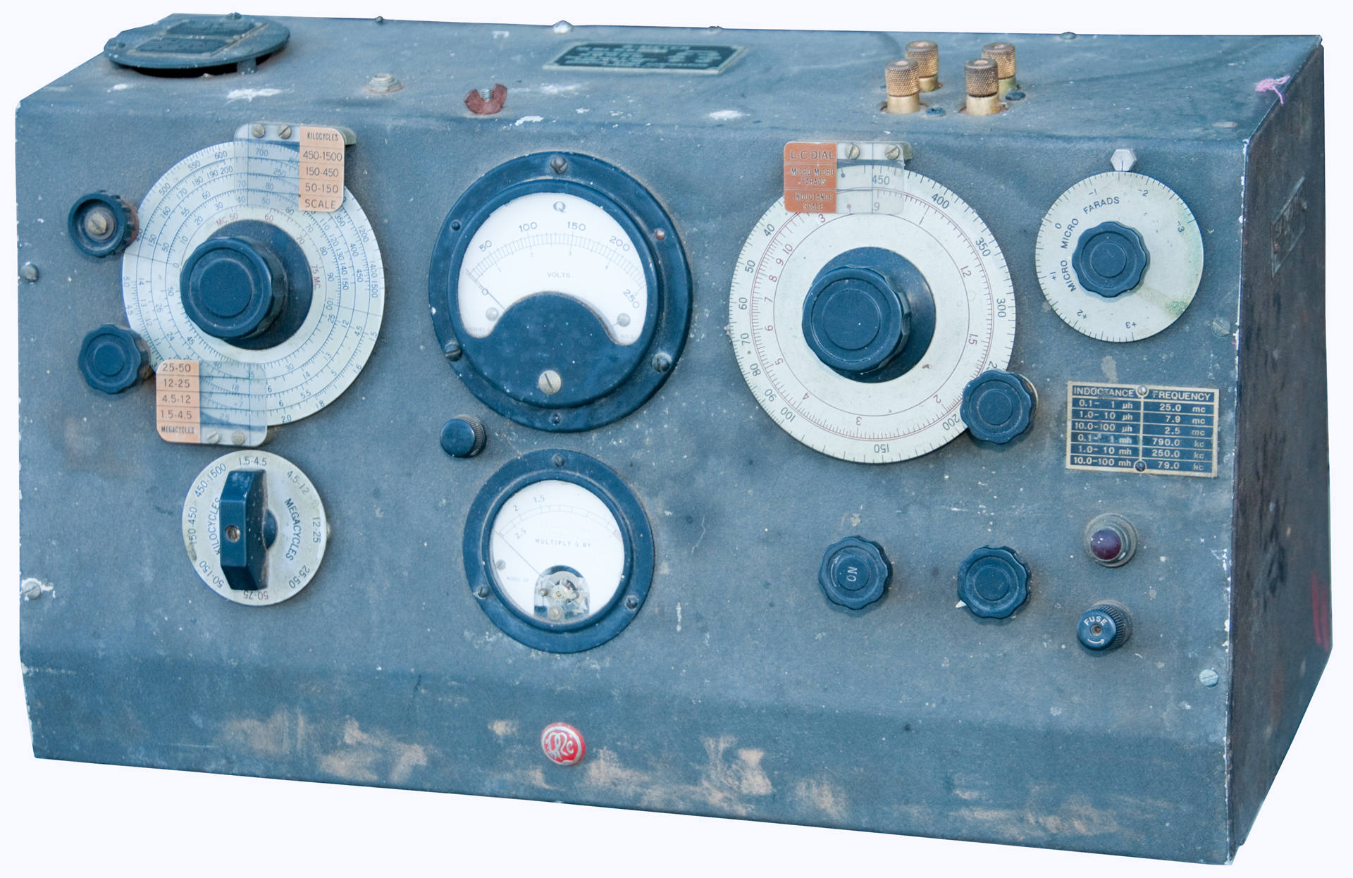
Covers 50 kHz to 75 MHz. The 50 kHz is important because it allows testing WWVB 60 kHz loop antennas.
When I got my first 160 Q-meter the thermocouple was bad so I sent it to a guy in San Jose who installed a replacement thermocouple.
I've read recently that to allow the meter to have a longer useful life you might set the oscillator level to 2 instead of 1. This idea being to use a lower power which requires multiplying the displayed Q by 2 (or some other factor). But I just set it at full scale (1) all the time.
First 160 Q-meter
This one was rebuilt prior to using it for coil measurements.
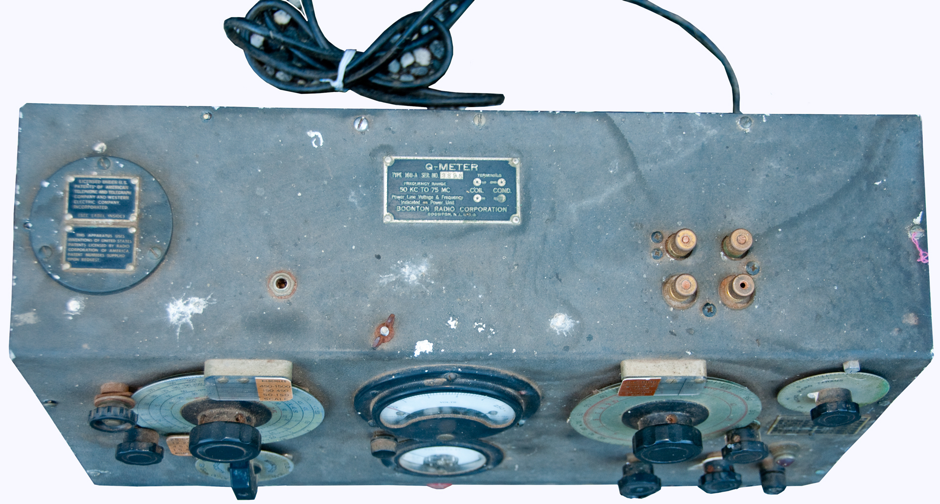
Second 160 Q-meter
Got this one for spare parts to maintain my first working unit.
Need to check if the Banana sockets are the same pattern
on the Heathkit as for the 160. The 160 is the standard and
there are a number of reference inductors to fit it.
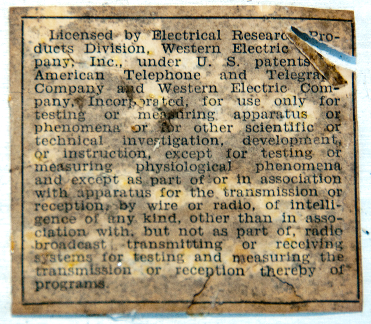
On the top of the circular vent plate the labels talk about
using patents of AT&T, WE and RCA.
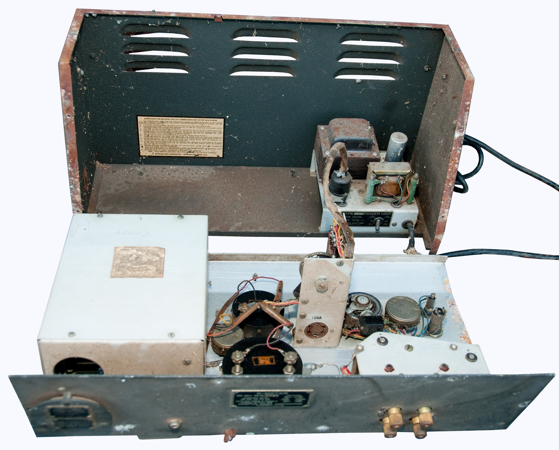
The 8-pin 5W4 power supply tube is missing.
The 5Y3GT can also be used.
The 6-pin Boonton special number 105-A tube is missing.
This is a special tube that's similar to the Boonton special
number101-A or 101-B.
BRC535B is a selected 1659 (Radio Museum)
The 1659 is a selected 2A6 or 75.
You can see it's plate cap just behind the front panel.
This is the vacuum tube voltmeter that measures the Q.
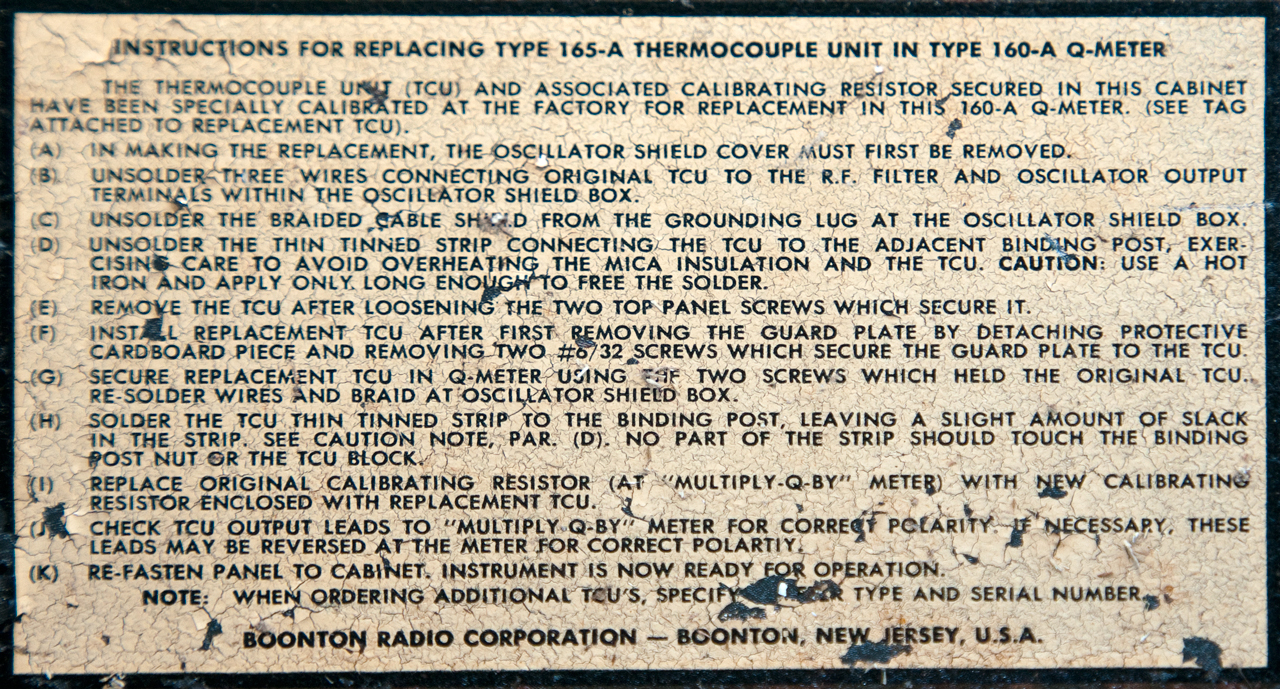
Instructions for Replacing Type 165-A Thermocouple unit in
Type 160-A Q-Meter.
Licensed by Electrical Research Products Division, Western
Electric Company, Inc., under U.S. patents of American
Telephone and Telegraph Company and Western Electric
Company, Incorporated, for use only for testing or measuring
apparatus or phenomena or for other scientific or technical
investigation, development, or instruction, except for testing
or measuring physiological phenomena and except as part
of or in association with apparatus for the transmission or
reception by wire or radio, of intelligence of any kind, other
than in association with, but not as part of, radio broadcast
transmitting or receiving systems for testing and measuring
the transmission or reception thereby or programs.
For more examples of this see the HP 415 - HP 200A.
The main oscillator 4-pin tube is missing.
Type 45 or later Boonton special number 102-A
BRC536A is a selected #45 tube
This is the meter I used for a number of years. It covers down to 50 kHz and so can be used for WWVB loop antennas as well as for other H.F. coils. Boonton also made a VHF range Q-meter but I haven't used it. HP bought Boonton in 1959 and continued selling Q meters for some time.Introduced by Boonton in 1934.
TM11-2635 TS-617B/U 3 January 1945
TM 11-6625-471-24P-4 TS-617C/U March 1977
This was written for the Boonton/HP 260 Q-meter which is very similar to the 160.
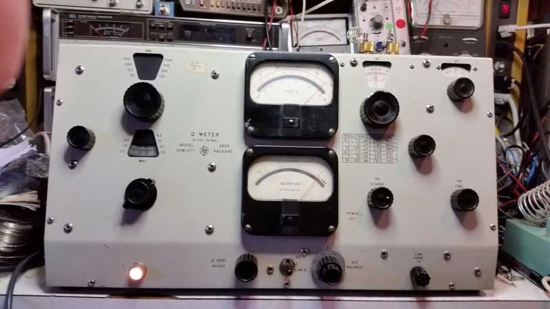
HP 260A Q-Meter Restoration
Mike White KC9SOA, April 12, 2017
Last year, I picked up an HP (Boonton) 260A Q-Meter at the ARCI radio club donation auction for ~$5.00. At the time, I knew virtually nothing about Q-meters. I knew about the importance of Q for resonant circuits, and if this was a way to measure it, that would be a good thing! Besides, it was HP, so it must be worth at least $5.00?
I took it home, and started researching online. I was intrigued by the seemingly simple design, the lab quality construction, and particularly the hot wire thermocouple voltmeter for the “Multiply Q By” function. I also read the cautions that most sites raised about the unobtainable RF voltmeter tube (it was missing in my 260A) and burned out thermocouple assemblies. A FET replacement circuit seemed possible for the tube, but no one said they’d tried to actually repair the thermocouple assembly.
I removed the back from the 260A, and was pleased to see that there was no evidence of any catastrophic failures; the usual dust and grime was present, but not excessively. Apart from the voltmeter tube, all the other parts were there. I did an ohmmeter check of the thermocouple assembly, and both the heater and the thermocouple read open. Not good news! But I wanted to assess the rest of the unit, so I decided to come back to this later.
Fig 1
I determined that the 40Mfd electrolytic filter cap was good. I tested the 6X4 rectifier tube, and decided to replace it with NOS tube I had on hand. I made a jumper plug to replace the CV transformer, and tried firing up the power supply. Once the B+ came up, I noticed bright orange flashes coming from one of the regulator tubes (?). I replaced it with another one from the tube bin, and the power supply was working normally again.
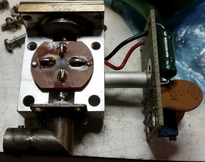
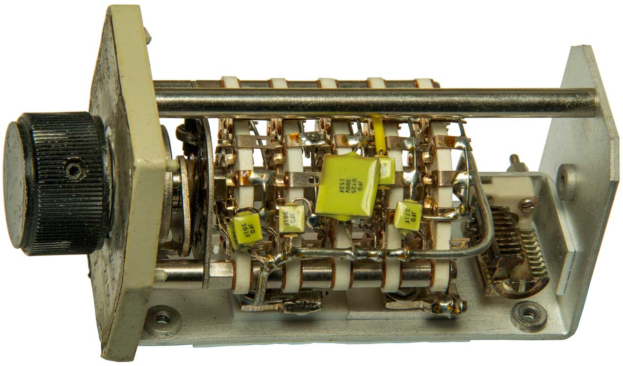
I checked the oscillator, and found three of the bands had no output. I removed the heavy duty cast metal assembly from the case, and took off the covers. To me, the band switch arrangement looked very much like the turret-style tuners used in early 1950’s TV sets, and considering when the 260A was designed, this was a logical and convenient way to design it.
One of the online sites said to check for broken wires from the oscillator coils to the rotor pins, and this was indeed the case. As the author suggested, I was careful not to stress the wires as I reattached them. This repair got the oscillator going, but I decided that since I had the assembly on the bench, I would go ahead and replace the old carbon comp resistors and bypass caps. I also cleaned the rotor contacts, and installed a NOS 5763 tube, before re-assembling the oscillator and re-installing it in the 260A.
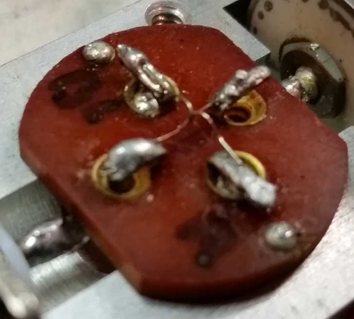
I was feeling better now about the prospects for this unit. I repeated the ohmmeter check of the thermocouple assembly, with the same results as before. The ohmmeter read close to .02 ohms for the injection resistor, so that was ok. I felt there was nothing to lose, so I removed the thermocouple assembly from the 260A, and opened it up. The problem was obvious; the heater wire had gotten so hot, it melted open, and also took the thermocouple junction with it. I didn’t see any signs of loose metal fragments in the cavity; instead, there was evidence of a possible flash event, with a deposit of some sort on the Bakelite insulator. There were the stubs of the heater and thermocouple wires still soldered to the terminals on the Bakelite insulator.
I was able to measure the diameter of these with a digital caliper. I also measured the distance between the heater terminals. From this data, I deduced the following:
Fig 2
Heater Wire Gauge = #37 AWG (.0045” diameter)
Thermocouple Wire Gauge = #46 AWG (.0015” diameter)
Length of heater wire = Measured distance between heater wire terminals = 0.209” (5.3mm)
From another online site, I learned the measured resistance (cold I assume) of the heater is supposed to be 0.3 ohms. Knowing the length of the wire, and its measured resistance, we can calculate the resistivity per unit length of the heater wire:
0.3 ohms / 0.209 inches = 17.225 ohms / foot
#34 AWG Nichrome wire is a close match for resistivity, although slightly heavier gauge.
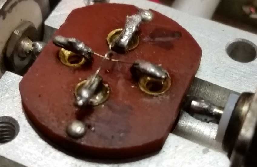
I didn’t have the Nichrome wire handy, but I wanted to see if I could find something that would work. I had some old “brick” style power resistors from the 1960’s and 1970’s in the junk box, so I broke a few apart, unwound some of the wire, and measured the resistance of a 0.2” length. Closest was from a 100 ohm 2W. I soldered a short piece across the heater terminals of the Bakelite insulator. I made a thermocouple using some #30 AWG type J thermocouple wire I had, and soldered it to the thermocouple terminals on the Bakelite insulator. I made sure to dress the thermocouple above the heater wire, with the junction at the mid-point. I then bent the junction to face downward until it was nearly touching the center of the heater wire. I charged a 1000Mfd electrolytic cap up to about 8V, hooked one end to the heater wire, and the other end to the thermocouple, and gently pushed downwards on the thermocouple until it touched the heater wire. This produced a little spot weld, effectively tacking the two crossing wires together at the point where they crossed.
Fig 3
Fig 4
Fig 5
I reassembled the thermocouple assembly, reinstalled it into the 260A, and connected a piece of 75 ohm coax to the BNC. The other end I attached to a variable DC bench supply capable of 2A. I turned on the bench supply, and as I increased the voltage, I saw the Multiply Q By meter begin to move! I increased the voltage until the current meter on the power supply read 1A. The needle on the Multiply Q By meter should have been around the x1 mark at the right side of the scale. Unfortunately, it only made it as far as half scale.
The HP version of the 260A has a 10 turn pot in series with the Multiply Q By meter, so I tried adjusting that. At minimum resistance, I could not quite get the full scale reading. This was disappointing, but nevertheless, I was in business now!
Besides finding little specific information on line about the design of hot wire thermocouple voltmeters, I also found little in my home library, this despite having books dating back almost 100 years. I also have WW2-era and postwar textbooks and references. What little I did find suggested that the gauge of the wires was important, and that was about it.
I knew that using heavier gauge wires for the heater and thermocouple would result in a longer thermal time constant, but I reasoned that would make it more resistant to damage from excessive current. The measured cold resistance of the heater across the BNC connector is 0.424 ohms, 0.122 ohms higher than the target value given on line.
One piece of information I sought was the “type” of thermocouple used by Boonton / HP. There are numerous types, each type having its own unique electrical response. I couldn’t find any mention of this online, so I looked for comparative data on thermocouple types. Type E has roughly twice the output voltage as the more common type J I was using, so I bought some, and gave it a try. Sure enough, I saw a much higher reading on the Multiply Q By meter, and was able to set the level for the X1 reading to .02mV, equal to 1A through the injection resistor.
However, the readings at the higher Q multipliers (X1.2, X1.5, X2) did not track the injection current. The errors increased as the Q multipliers got progressively higher, and were above the limits allowed in the alignment procedure. Boonton calls this condition a “mismatch” between the thermocouple assembly and the meter. Nothing I tried so far has been able to improve on this. A better match for the original heater wire could possibly help.
Next I built a solid state replacement for the voltmeter tube using a FET circuit from an online source. I wasn’t completely happy with the operation of the circuit, so I modified it slightly to provide a regulated +25V at the drain. Even with this, I could not quite get the Q meter scale to track exactly during calibration. The error is fairly small, but more than I’d like. Could be a problem with the meter movement, or the linearity of the FET?
Fig 6 FET replacement
I’m sure I’ll get the itch to dig into the 260A again at some point, and try to get it closer to properly calibrated. I also intend to rig up some coils as “standards” with known Q’s, for reference use.
Now that almost all of the 260A was somewhat functional, I started measuring inductors from my junk box. I’m not quite sure why, but I found I really enjoy operating the Q meter! And it’s interesting to put real values to the parts in the junk box; all of a sudden, they start to look useful, and new projects come to mind. I also came to realize that exact Q readings aren’t always required. That’s certainly the case when you’re trying to measure a capacitor, or dial in what value C you need to resonate with the inductor you’re measuring.
The last thing I did was to reconnect the constant voltage transformer. It works! I got good regulation from under 100VAC to over 120VAC. There is some audible buzzing from the transformer core, but it doesn’t get very hot, so I think I’m going to go with it for now.
Fig 7
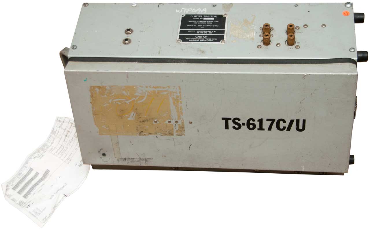
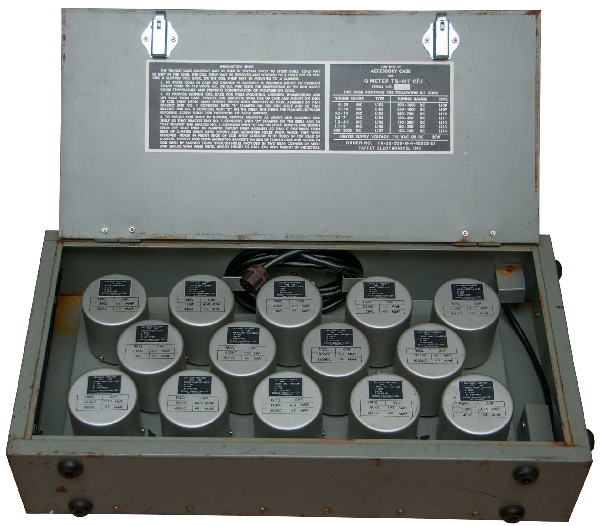
The TS-617 is the military version of the 160 Q-meter. This version covers 50 kHz to 75 MHz. It includes a case of 14 inductors covering the range of 1 uH (8 to 20 MHz) to 25 mH (50 to 140 kHz).
The oscillator tube is a 5763. The VTVM and Bucking Diode use a 5726/6AL5W tubes. The balanced amplifier uses a 5814A tube. The AC rectifier is a 5Y3W GTA tube.
Instead of a thermocouple this version uses a simple resistor divider circuit. The oscillator signal goes through three parallel 2.7 Ohm resistors (0.9 Ohms) then to the Lo Coil terminal. From the Lo Coil terminal to ground is a 0.03 Ohm resistor. The Vacuum Tube Voltmeter (VTVM) is connected to the Oscillator.
Photos
Fig 1 Carry handle at left & feet at right.
Fig 2 Single meter with switch for level or Q
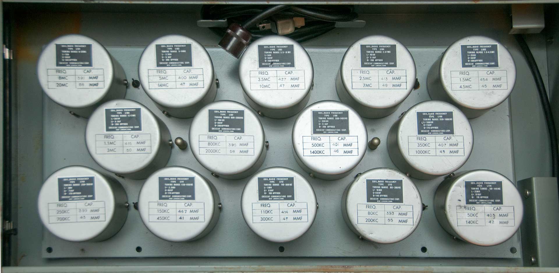
Fig 314 Coils
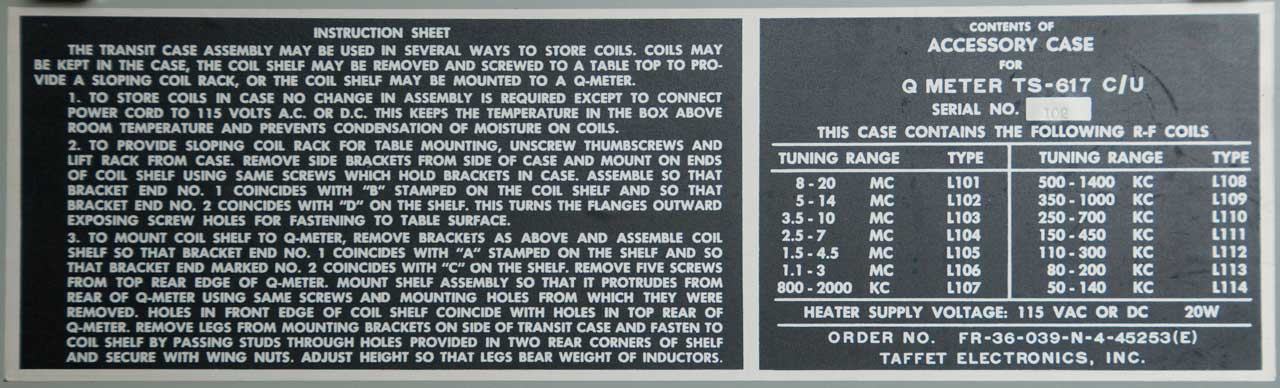
Fig 4 Three coil mounting options
Fig 5 Power cord is for 20 Watt heater in coil box
Manuals
TM 11-2635A Q-Meter, TS-617B/U, Feb 1956 with changes 1 to 5 (Aug 1976).
TM-11-6625-471-24P-4 Org, DS, GS, Maint Repair Parts for Q-Meter TS-716C/U, March 1977
Q Standard, Hermetic, 250 uH
This is the broadcast band inductor.
The table shows:
L=250 uH, Cd=8.3 uuF
Freq (MHz)
0.5
1.0
1.5
Qe
189
247
215
Qi
181
232
193
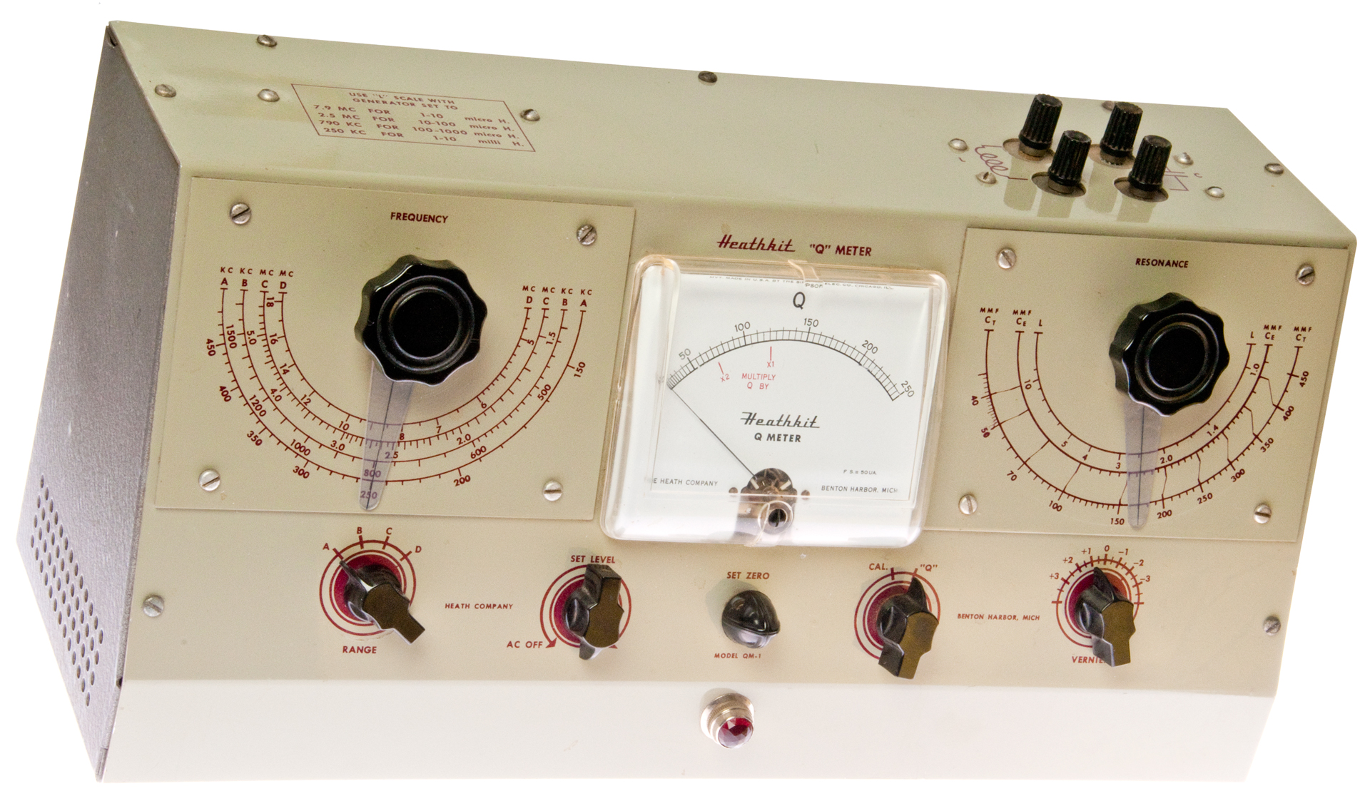
Covers 150 kHz to 18 MHz, does not cover WWVB loop antennas at 60 kHz.
It uses a constant current to the coil so that the voltage across the coil is proportional to the Q. That avoids using a thermocouple.
(Heathkit QM-1 Q meter.pdf)
Maybe introduced in 1951. It has the layout of the Boonton 160.
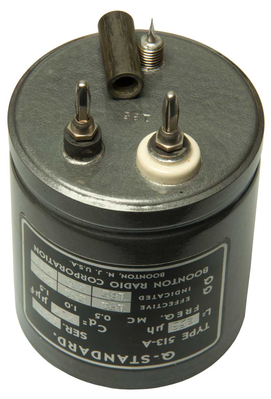
The Q standards come in two types. One has a removable metal can and in the other the can is hermetically sealed.
Both types have Banana plugs spaced to match the Banana sockets on the top of the Q-meters.
A quick look in a very full shipping container did not uncover an example.
You can see them on Google Images.
I phoned NBS and asked the inductor guy how they calibrated the Q standard and the answer was by comparing it to their in house "gold" standard inductor.
Data sheets for the 513-A and 518-A Q Standards (everist.org)
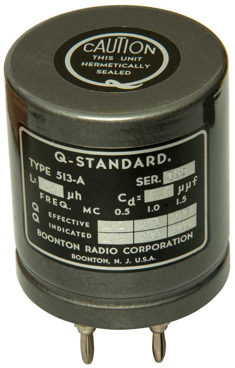
Boonton 513-A AM Broadcast Band
I have an interest in Crystal Radios so got this Q standard.
This is a nominal 250 uH (marked 253 uH) inductor which when resonated with the standard 365 uuF variable tuning capacitor (Wiki) will tune the AM broadcast band (Wiki).
The band used to be 550 to 1600 kHz in 10 kHz steps.
There are two types of Boonton hermetically sealed Q-Standards. The ones with type numbers ending in just -A and those with a type number ending with -An, where n is an integer like 1, 2,3 or 4. AFAICR the plain -A suffix units can also be used to confirm the the operation of a Q meter, whereas the letter number suffix standards are for use as references when making Q measurements.
Label
Q-Standard.
Type 513-A Ser. 185 (also stamped on bottom)
L= 253 uH Cd= 7.7 uuF (distributed capacity should be much lower than resonating capacitor to get high Q)
Freq (Mc)
0.5
1.0
1.5
Q effective
191
251
227
Q indicated
182
236
203
Boonton, N.J. U.S.A.
Calculated Tuning Capacitor C=1/(4*PI*PI*L*f*f)
C tuning (uuF)
400
100
44.5
Fig 1
Fig 2
Inductance Patents
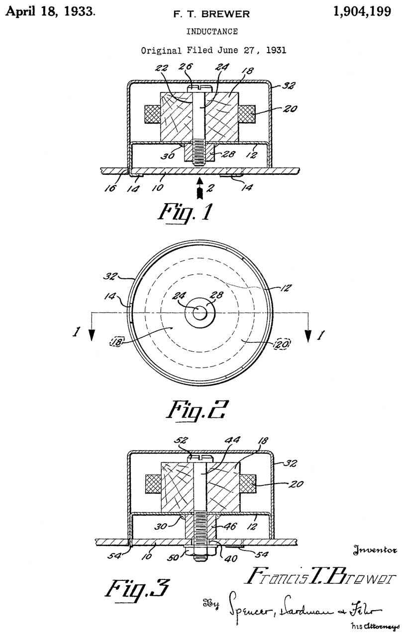
1904199 Inductance, Francis T Brewer, General Motors Radio Corp, 1933-04-18, -
In order to have a small shield surrounding an air core multilayer coil and maintain it's high Q
a conductor (bolt 26) is run through the center of the coil.
When measuring high Q coils they would be effected by objects at least a few coil diameters away.
So to have a shield can that's less than a coil radius away and not degrade Q is quite an accomplishment.
This may be implemented in the Q standard coils?
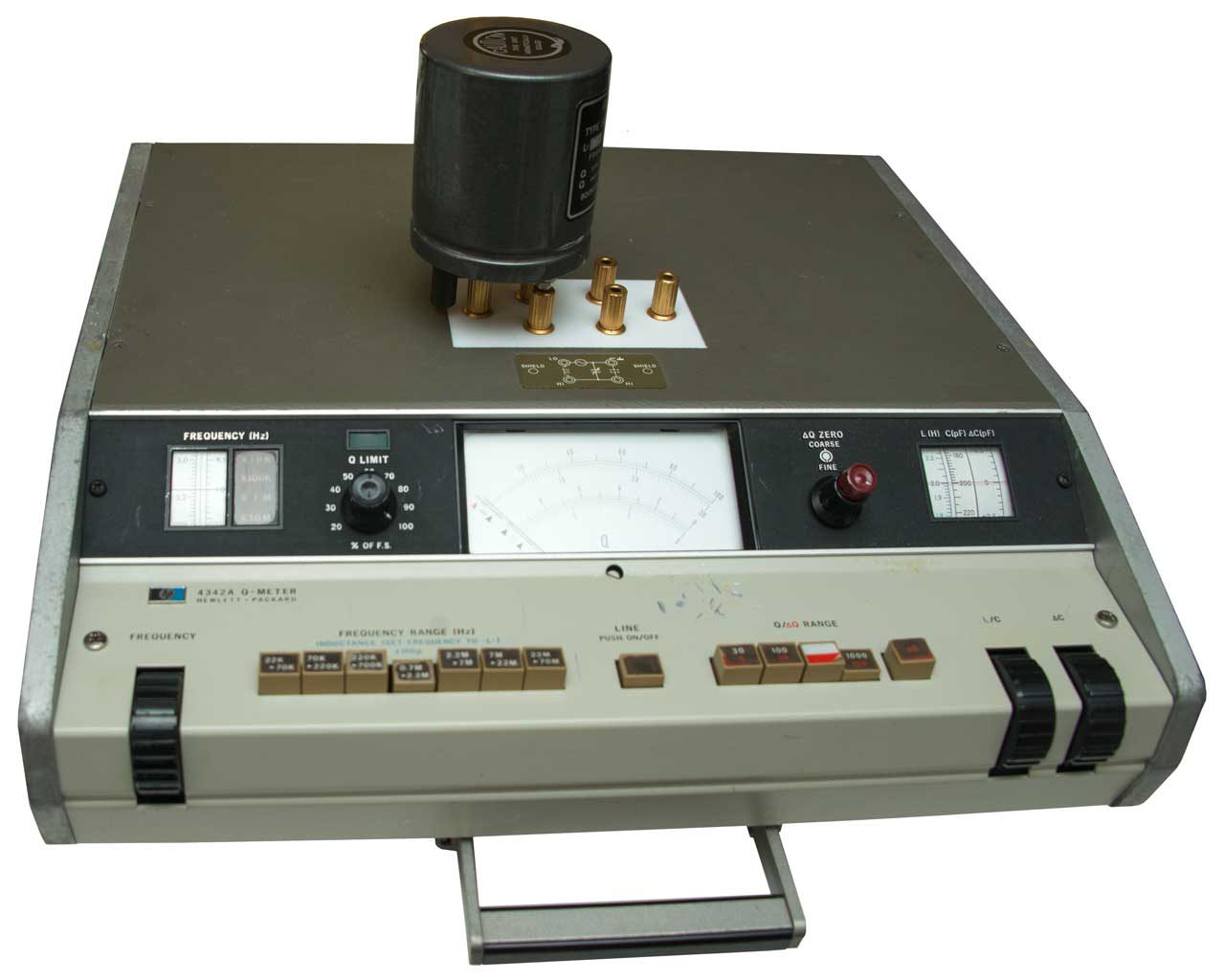
HP bought Boonton in 1959. HP developed the 4342A Q-meter that covers 22 kHz to 70 MHz.
The HP 42851A Precision Q Adapter has a motor to turn it's internal resonating capacitor, I haven't used this instrument and it only works with the HP 4285A LCR meter.
This is a very expensive setup, even used, since it may be the most accurate (lower total errors) way to measure Q.Design References
HP Journal Sept. 1970: Measuring Q-Easier and Faster, S. Kito & K. Hasegawa - 4342A - uses gold plated capacitor,
calls: Methods of Measuring Impedance - HPJ Jan 1967 cCrystal Radio EU - Experiments with LC circuits part 1 3 Coil comparison - Part 2 Coil type comparison - Part 3 Litz wire - Part 4 Variable Caps - Part 5 nearby objects - Part 6 nearby objects - Part 7 solenoid coils on different formers - Part 8 turn-to-turn capacitance - Part 9 Q of variable caps - Part 10 Rin of Measuring Amp -
alls: A novel Impedance-Measuring System Using Standard HP Instruments HPJ July 1952: An audio oscillator drives a network consisting of a series 1 Meg resistor and then the shunt connected DUT, followed by an HP 400 or 330 VTVM. Other circuits allow measuring other DUT, for example a series capacitor DUT is followed by a shunt 100 Ohm load (HP 470D) at the VTVM input.
4342A
Waited a few hours after it was delivered so it could cool off. When powered up tested using the 513-A Q-standard at 1 MHz. The Q limit knob needed to be set to 100% and the range set to 1000. But then the needle bounced up and down scale accompanied by a buzzing sound coming from the center left of the 4342A, the it sound stopped and the needle went to zero.
Troubleshooting
Opened top cover did not see anything amiss and not smell of burned components.
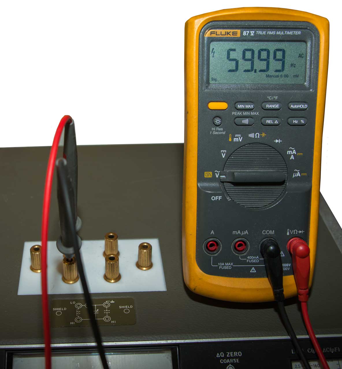
The Fluke 87V DMM can measure AC voltage and frequency up to 200 Khz so set the 4342A to 100 kHz and measured the coil terminals. Reads a little more than 300 mVAC and 60 Hz! So the oscillator is not working. On the 30 Q range and the lowest oscillator range the output can be adjusted to 2 kHz at around 100 mVAC. The oscillator output should be a little below 1 VAC.
The Troubleshooting flow diagram starting on page 5-22 of the 04342-90009 pdf manual is not at all usable because the foldout has been chopped up into many unmarked pages.
Fig 1 First Power up July 30, 2022
Fig 2 Fluke 87V Oscillator check
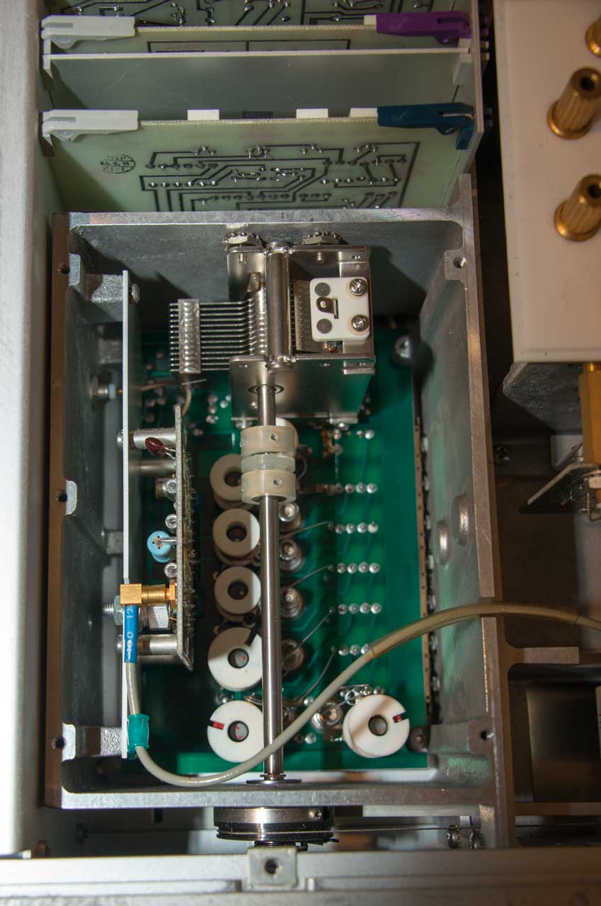
Fig 3 Inside Oscillator box -
no bad smells
Fig 4
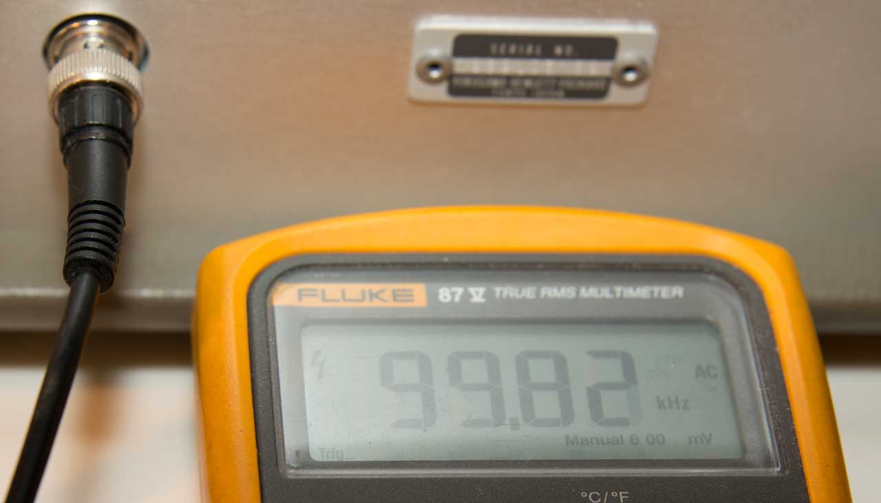
Frequency Monitor Output,
BUT . . .It does not repeat! Next time showed 8 kHzBad test lead, it does repeat 99.82 kHz
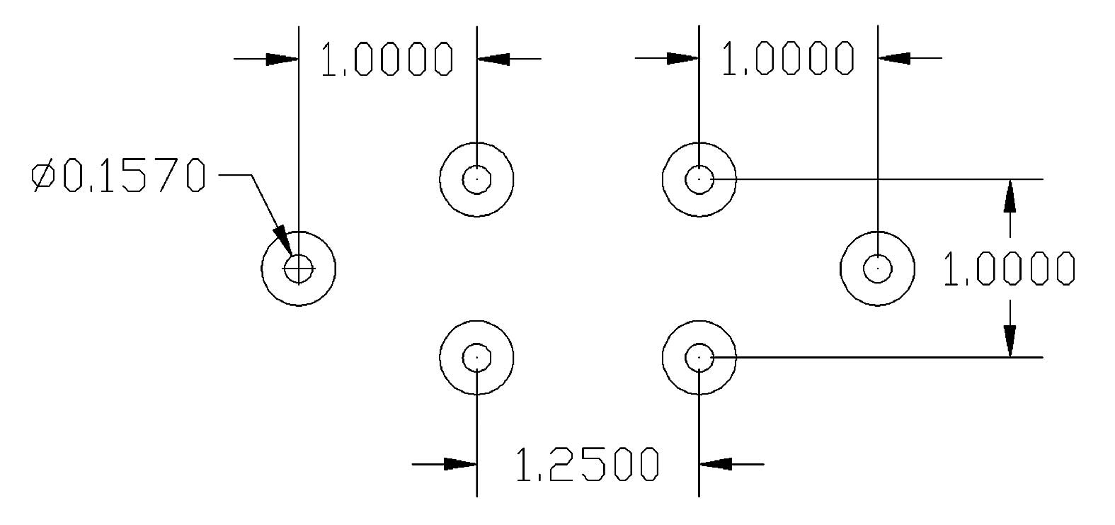
Fig 5 Terminal Layout
With no wires and the sleeve screwed down
the terminals are about 3/4" high.
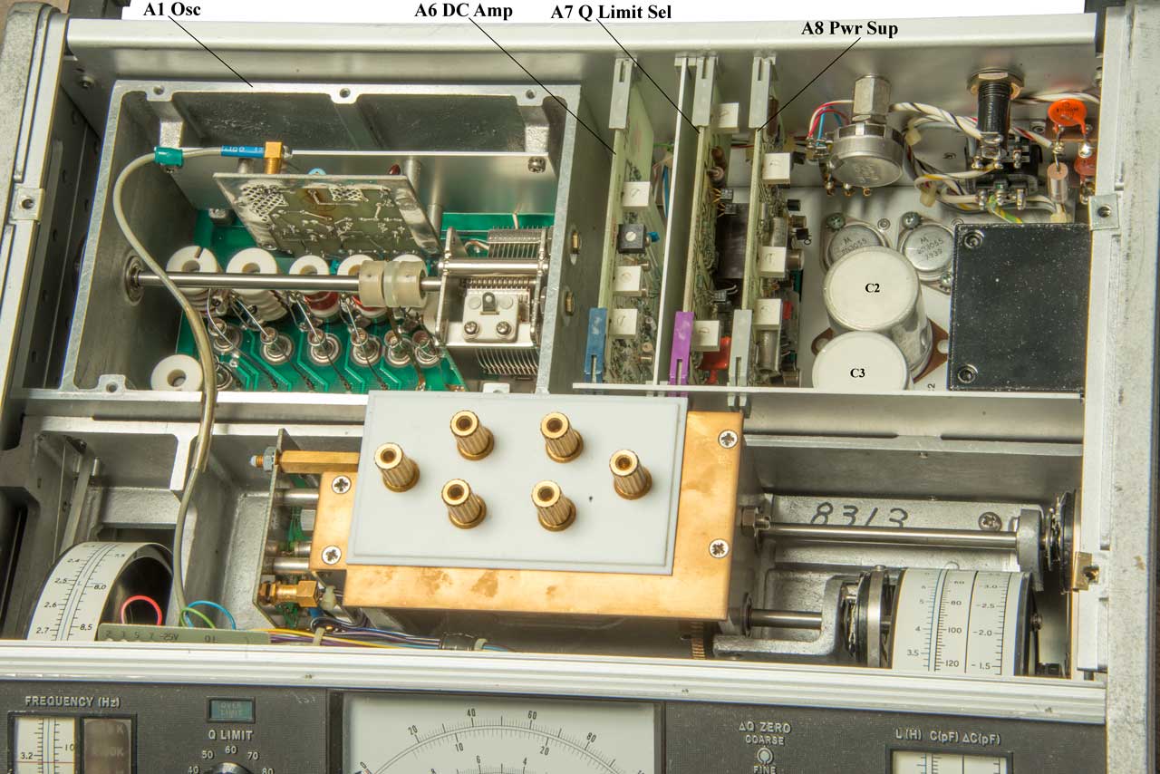
Fig 6 Top major components
Fig 7 A8 Pwr Sup PCB
Caps & some components labeled
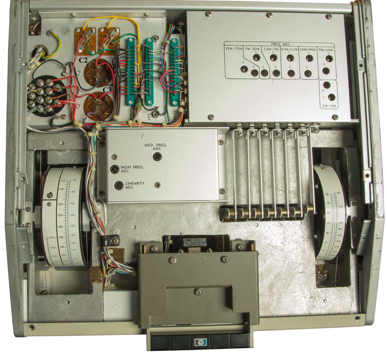
Fig 8 Bottom C2 & C3 labeled
The next day I was going to see what effect disconnecting the gray cable coming out of the oscillator box would have, but the Frequency Monitor output was dead. Next need to cut and tape of the schematic for the power supply (I already have: Troubleshooting, Fig 8-2 Overall block, 8-3 Oscillator & 8-4 Tuning Capacitor).
Power Supply Caps
Nomen
Spec
uF
Meas
uF
Meas
ESR
A0C2
1000
1100
0.3
A0C3
1000
1300
0.6
A8C2
1
1.1
10
A8C3
47
55
1
A8C5
1
1.2
10
A8C6
47
54
0.6
A8C7
1
1.8
15
A8C8
1
1.5
17
A8C9
0.22
0.24
45
A8C10
0.22
0.24
43
Parts
Read a post where the input FET was burned out and replaced with a 2N4416A (pdf) N-Channel JFET
A4Q1: 1854-0091: TRANSISTOR NPN SI TO-5 PD=600MW SG1681 = SM9104
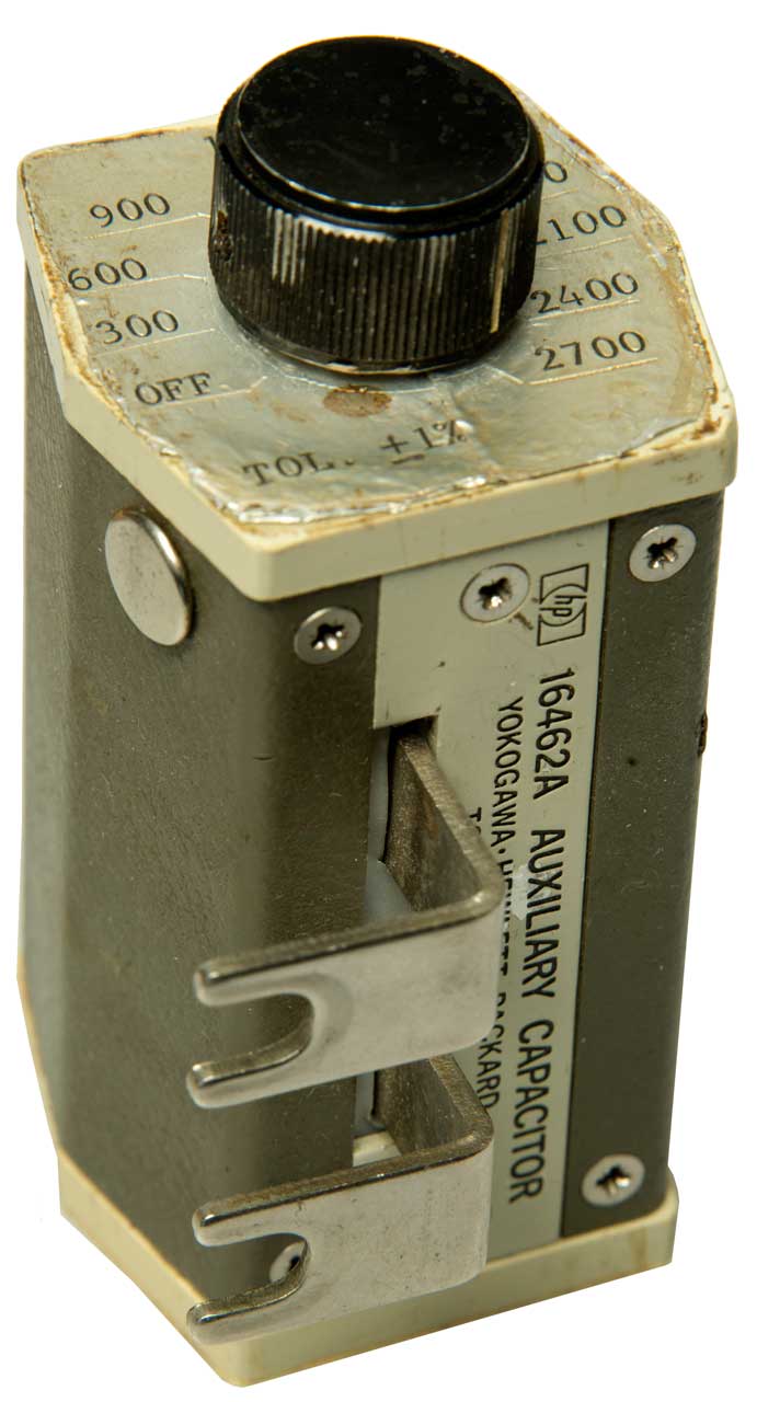
16462A Auxiliary Capacitor
This is a device containing nine 300 pF capacitors and a switch. Any number of them from none to all nine can be switched into the circuit. This allows testing inductors with more capacitance than is available in the 4342A Q meter.
Fig 1
Fig 2 Inside
1628983
Electrical network, Kenneth
S Johnson, Western
Electric (prior to Bell Labs), 1927-05-17, - Johnson used
the upper case Q to represent the ratio of reactance to resistance
in inductors and capacitors. He is the father of the term
Q.
Reference: Bell Telephone System Monograph 2491, The story of Q by
E.I. Green. First published in American Scientist, Vol 43, pp.
584-594, October, 1955. (pdf)
Starting on doc pg 3 (pdf pg 5) is a discussion of what we now
call Ring Down including the equations for it.
Q = PI/d
where d is the logarithmic decrement = LOGe(AB/CD)
AB is the zero to peak voltage at the start of a ring down,
CD is the zero to peak voltage one cycle later.
n=(Q/PI) * LOGe(p)
p is ratio of initial amplitude to final amplitude (always greater
than 1)
n is the number of cycles to go from initial to final amplitude.
PS This also applies to:
bouncing balls (doc pg 10, pdf pg 12): Golf ball Q=9, Tennis balls
slightly less.
The Earth Q is about 10E13.
Cesium Q about 30 to 50 million.
HP makes a distinction between meters that make a measurement at
a single point and analyzers that have a graphical plot of many
points. So the first step in making better Q measurements
would be to have an analyzer rather than a meter.
This would allow using curve fitting the measured data to a model
of the device allowing a more precise answer. This might be the
Darko S11 circle fit, or maybe a fitting to a more accurate model.
But an even more important capability would be analyzing the
slope of the Q v. Frequency curve. This gives an indication
of the loss mechanism(s) that are in play.
The internal capacitance of an inductor ultimately causes self
resonance, but prior to that it lowers the Q.
The physical bulk resistance of the wire effects the Q so winding
the coil in such a way as to get the most inductance for a given
length of wire lowers this effect. For a single layer
solenoid coil AFAICR it should be squat and fat where the diameter
is about 1.5 X the length. Not at all how commercial Tesla
coils sold to schools look.
Skin Effect also can be a loss mechanism that can be mitigated by
the use of Litz wire.
Origin of Q &
Ring Down in their own paragraph.
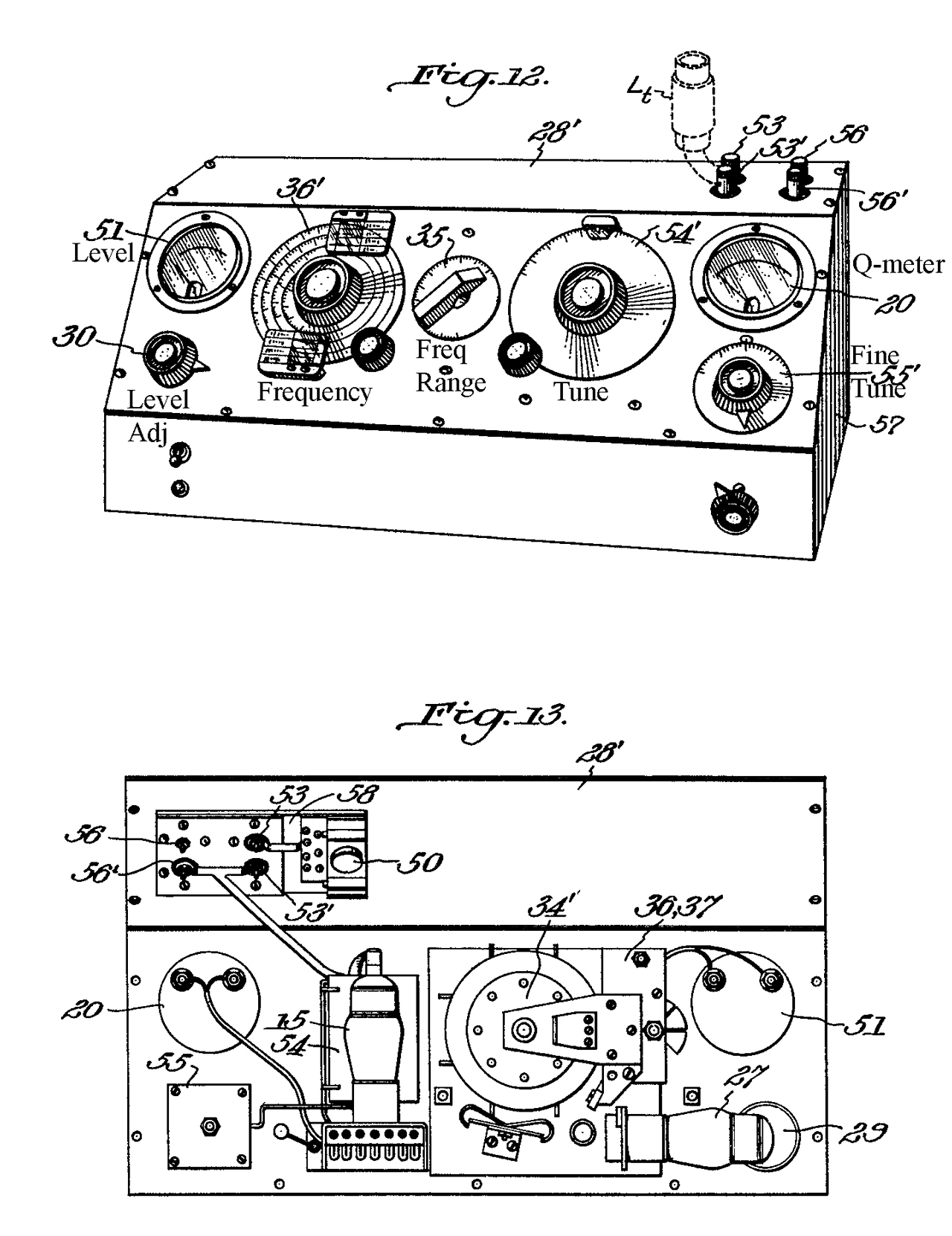
2137787
Method and Apparatus for Electrical Measurements, Harold
A Snow, Boonton
Radio Corp, Nov 22, 1938, 24/654, 324/653,
338/61
This appears to be the starting patent for the model 160
Q-meter.
The early part of the patent is about how to make a 0.04 Ohm
resistor that has a small amount of inductive reactance up to 30
MHz.
The Heathkit QM-1 above uses a capacitor instead of the special
resistor used by Boonton.
27 is the oscillator tube and 35 is the VTVM tube.
Inductors
flux gate magnetometers
Metal Locators
Magnetics - Including Magnetostriction
General Radio GR 650-A or GR 1650B Impedance Bridges
HP4260A LCR meter
HP 4261A LCR Meter
HP4274 or 4275_LCR
HP 4332
HP395A HP 4395A Combination Network, Spectrum, Impedance Analyzer
Loopstick Antennas
Marconi TF-2700 Universal Bridge.
Joule Thief
Stanford Research SR715 LCR meter
Xam Crystal Activity Meter
Xec Crystal Unit Equivalent Circuit
Xtal Electronic Crystals
Xtal1800 Crystal Radio 1800? & Brooke Clarke #1
Xtc Crystal Temperature compensation Patents
ZM4 ZM-4 Bridge battery powered
ZM11 ZM-11/U Capactance-Inductance-Resistance Bridge, line powered
Z - Impedance requires test fixture and and way to de-embed the fixture's parasitics
Zo Transmission Line Zo vs. Frequency
NPLReport MAT 58: Q-factor Measurement by using a Vector Network Analyzer, Gregory, Dec 2021, 105 pgs,
Test Equipment. The Neglected Q Meter. - useful info
Experiments with Coils and Q-Measurement Wes Hayward, w7zoi, October, 2007 (Updates 01Dec07, 08Dec08.) - ZPR (Zero Power Receiver, HP 4342A)
Fun with Tubes - Test Equipment: The Neglected Q Meter. -
HP Archive - Boonton - Links to Boonton Equipment Manuals, Catalogs, and “The Notebook” are below …
EDN: Aug 2013: Novel Q-meter -
Silicon Chip: Feb 2005: Inductance & Q-Factor Meter -
Q factor measurements, analog and digital, Darko Kajfez - curve fitting either magnitude only or the resonator plotted on a Smith chart shows up as a circle. (MATLAB) (Archive.org)
An Experimental Q Meter by VK5BR - in the end he ended up measuring the two frequencies for 0.707 of the peak.
The Two Faces of Q - W7ZOI -
Experiments with Coils and Q-Measurement, W7ZOI
Q Factor Measurements on L-C Circuits, VE2AZX -
EEE Guide: Q Meter - equations, plus using for impedance and transmission lines measurements
YouTube: Russian Q meter, 1:44 - 34.8 uH Q standard with case removed, Tested on LCR meter (39.8 uH), Tesla BM 560 Q meter @ 2.525 MHz (Q: 140 with 195 pF), Scope: 2.541 mHz
An Experimental "Q" Meter, Lloyd Butler VK5BR - with information on Distributed coil capacitance
Building a Q Meter, Jim Tregellas, VK5JST - How to Make your own Q meter 2004, with details on construction
Practical Wireless Nov 1978: Sarum Q Meter, M. Tooley, pdf pg 60 (on line pg 51)
Ring Down
Measuring the Q-factor of a resonator with the ring-down method - "count how many cycles it takes to halve the amplitude and multiply this number by 4.53 to find Q". A tuning fork is used as an example. The Flyback Tester (they are hiding so ask before ordering) works with this method.
YouTube:RING DOWN Q METER, 0:54 - Ring-down Q Improvement, 1:01, dx 5 inch Loop, 5:19 - Inductor Tester, 10:00 - uses the ring down method and measures the frequency of the damped wave and does not look at the amplitude decay, but that could be added.
CrystalRadio.cn - Ring Down Q tester - Supplemental 1 - New design w/schematic & photos -
YouTube:
ATMEGA88 version 2021-4-8 at Crystal Radio -
YouTube: Measuring Self-Capacitance and Self-Resonant Frequency SRF of Inductors, 36:39 - @17:00 Square wave generator ( 1 kHz) - 10M series resistor, inductor to ground, 10M high-Z scope probe - scope; @21:15 the amplitude is 1/2 of the initial (does the peak count?) in 10 cycles, times 5 (Thompson's formula f = 1/(2PI*sqrt(LC)): 10th cycle is (1 - pi/50)^10 = 0.522) Q=50; @23:27 using cursors to measure self resonant frequency: 680.3 kHz; @33:12 the self capacitance of the 2 mH coil is calculated; See <CTRL>F comments by keithammleter3824 which are very good. Magnet-Field Antennas & Crystal Radios Play List -
Back to Brooke's: Contact,
PRC68, Alphanumeric
Index of Web Pages, Products for
Sale, Test Equipment, Microwave Test Equipment, Military Information, Electronics, Personal
Home page
Page created 12 Oct 2013.