Seeing the photo (External
link) of the Boonton 33A "Admittance Bridge" front panel
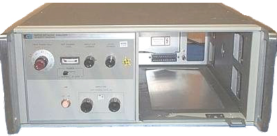
reminded me of the HP 8410 Vector Network Analyzer.
Prior to the 8410 transistors were specified using h or y
parameters and these required testing the transistor using either
an open or short circuit AC load.
As the cutoff frequency of the transistors got higher and higher
in the early 1960s these loads resulted in oscillations that were
hard to stop, hence the 8410 that uses 50 Ohm terminations on all
the test ports.
There were a number of accessories for the 8410 specifically aimed
at transistor characterization.
There was an automated HP 8410 system in Palo Alto (or maybe
Mountain View) where I took bunches of microwave transistors to
get the characterized for S-Parameters. These were analyzed
using software I wrote that would combine the measured
S-parameters with common circuit elements including transmission
lines. This was run on a time sharing computer in Palo Alto
using an ASR-33 teletype in my office connected by an acoustic
coupler type modem. The billing was based on two factors, 1)
how much CPU time you used and 2) phone connect time. If the
computer went down during your connection all the bill would be
zeroed and start over. There was a very large
difference in the billing rates for CPU and connect time and the
computer often crashed. So it was my policy to leave the
terminal connected after the program finished running in the hopes
it would crash. This paid off most of the time. This
was a big step up from driving to a different computer with a
stack of punched cards to have the Fortran program run as a batch
job, correcting any mistake in the deck of cards and resubmitting,
etc.
The HP Journal for Feb.
1967 introduced the 8410A. Rereading that article in 2010
brought back the memory of attending the local HP introductory
meeting to introduce the 8410A. One of the reasons for it's
development was to come up with a better way of characterizing
transistors. The then common "h" or ''z" parameters required
either shorting or opening one of the transistor leads, which
resulted in microwave oscillations on the new hot Germanium
devices. One way to avoid that problem is to terminate the
transistor in 50 Ohms, hence the development of Scattering
Parameters (S-Parameters). I did a lot of searching of
government documents looking for "Scattering Parameters" and got
back many pages of 132 column computer paper that mostly had to do
with radar cross section stuff. On page 3 (Fig 2) in the
above article shows a scope connected to the 8413 Phase-Gain unit
and a BWO sweeper and there's a small box off to the right that I
don't remember. It turns out the small box is a 723A power
supply (0-50V, 100, 200, 400 or 550 ma current limit) powering the
filter under test.
I wrote a lot of computer code in FORTRAN and Basic to analyze
S-Parameters. At first this was done using punched cards and
driving them to the computer in Palo Alto (that's how I got a dent
in my 427 Cobra). Later used an
ASR33 Teletype in my office connected to Remote Computing Corp in
Palo Alto to do the analysis. They had a policy that if the
computer went down while you were working (i.e. while you were
connected) they didn't charge you for the prior computing
time. Since they went down often it was my policy to not
hang up after doing a calculation, but rather leave the modem
connected for the rest of the day. The gamble paid off
enough times that it was a good strategy. When the RCC rep
was visiting I told him about it as a motivation for them to have
fewer failures.
My key reference document for S-Parameters was App Note 95 (an95.pdf, an95-1.pdf)
The design of microwave transistor amplifiers in terms of getting
flat gain over the pass-band was straight forward. The hard
part was taming the out of band gain to prevent
oscillations. The narrow (L and S) band telemetry amplifiers
designed by Bob Mouw were made of modules. Each module had
an quarter wave resonator as the input coupling element and
another quarter wave resonator as the output coupling
element. When the module plates were installed into a
rectangular housing the input and output coupling elements would
line up. That's to say there was no RF
electrical connection between the stages, just the coupling
between the resonators. The beauty of that is there was only
in band coupling between stages. This not only eliminates
out of band gain/oscillation, but also eliminates distortion and
makes the amplifier act like a narrow band filter.
Prior to the HP 8410 microwave device Smith Charts were measured
using a slotted line one frequency at a time. This was a
tedious process. It took me about 1 day to get one Smith
chart over a reasonable band of frequencies. The HP 415E SWR meter
is just an AC voltmeter that has a very narrow filter centered at
1.000 kHz. Many of the signal generators had a built in 1
kHz modulation to support the use of the "VSWR meter". Also the
testing methods for transistors that worked OK at low frequencies
like "h" or "z" parameters did not work at higher frequencies
because the measurement methods required either an open or short
termination on the transistor causing it to break into
oscillation.
Noise Figure
The problem came when measuring Noise Figure on narrow
band 2.3 -
2.3 GHz unified S-band telemetry low noise tunnel diode
amplifiers. The HP 340 Noise Figure meter has a 30 Mhz
input. We often used a Narda type-N coupler and one of the
Tunnel Diode Detectors (made by us) as a mixer to convert
the L or S band signal down to the 30 MHz input of the NF
meter. Between the mixer and NF meter there was a low noise
AIL tube type 30 MHz IF strip.
The HP 349A Noise source was a rectangular box and we added a 10.0
(calibrated) attenuator to minimize the effect of the VSWR of the
noise source changing between the on and off conditions.
This is a double side band measurement, i.e. the NF meter sees
energy at both LO+30 MHz and LO-30 MHz. When testing what
amounts to a combined amplifier and filter with very steep skirts
(many stages of amplification is the same as many poles in the
filter) that's say only 100 MHz wide when the LO frequency gets
within 30 MHz of the pass-band edge the NF starts to
plummet. QA inspectors didn't come to us with an
understanding of how this works.
When testing the Log Video Amplifier used with our Limiter-Detectors
made for Applied Technology (then in the Stanford Industrial Park
just off Page Mill Rd) in Radar Warning
Receivers I modified the HP 343A Noise Source (as far as I
can remember) by bypassing a series capacitor so that the lower
frequency limit was DC.
The Log Video amplifier tested looks the same as the one in the AM-6536 / ALR-54.
3886451
Random phase modulating time base and method to improve
measurement averaging counter resolution, David C
Chu, John
H Gliever, HP,
1975-05-27, -
4023098
Noise burst source for transfer function testing, Peter
R. Roth, HP,1977-05-10,
-
Hot-Cold Noise Source
A more accurate way to measure noise figure is called
Y-Factor (Noise
in RF Systems). This involved a box made AFAICR by
Airborne Instrument Labs (AIL) that contained a couple of 50.0
Ohm microwave terminations with GR-874 connectors. One
of the terminations was in an oven at some temperature I don't
remember and the other was in a Dewar that we filled with
liquid Nitrogen.
The noise coming from a resistance depends on the value of
the resistance, it's temperature and the bandwidth (KTBR, Wiki).
8410 Components
The three columns are for the suffix letter. The date is for
the newest version of the manual, not the equipment date.
Model
A
B
S
8409
110 MHz - 18 Ghz
Semi-Automatic NA
08409-90002
March 1978
8410
Manual NA
08410-90020
December1971
08410-90521
July 1979
08410-91008
September 1969
-100 System 0.11-2 Ghz
-200 System 2-12.4 Ghz
-300 System 0.11-12.4 GHz
8412
Phase Magnitude Disp
08412-90010
April 1972
08412-90033
December 1981
8413
Phase-Gain Ind
08413-90011
May 1974
8414
Polar Disp
08414-90016
May 1973
8418
Aux Disp Holder
08418-90001
May 1980
08418-90028
July 1982
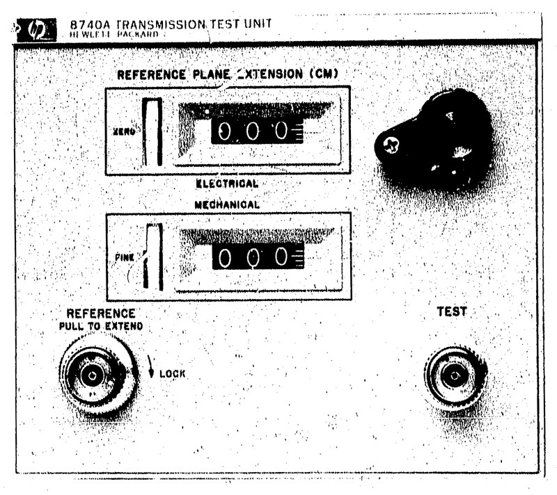
8740
Trans Test Unit
DC to 12.4 GHz
08740-90001
June 1972
8741
Reflection Test Unit
0.1 to 2 GHz
08741-90001
July 1972
8742
Reflection Test Unit
2 to 12.4 Ghz
--
8743
Reflection-Transmission Test Unit
2 to 12.4 Ghz
08743-90010
July 1972
8745
S-Parameter Test Set
0.1 - 2 GHz
08745-90009
February 1982
8746
--
905
1.8 - 18 GHz
Sliding Load
00905-90009
June 1984
907
1 - 18 GHz
Sliding Load
00907-90001
January 1979
11605A
--
11607A
--
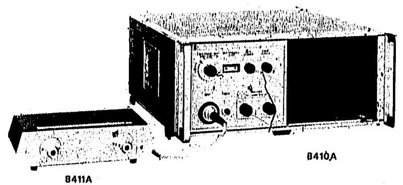
The 8410
would display the Smith chart in real time allowing
tuning. The 8411 Harmonic Converter has a reference and
test input port and inside a variable frequency oscillator
generating harmonics way up into the microwave region that acted
as the local oscillator to the reference and test mixers.
The down converted Intermediate Frequency was fed back into the
8410 main frame. The socket for the 8411 umbilical cord
could be on the front or optionally n the rear panel of the
8410. The 8407 is a lower frequency analyzer that covers
100 kHz to 110 Mhz. There is no separate frequency
converter, there are two direct inputs to the 8407.
There was a problem in automated
systems because the 8411 might lock onto the harmonic
just above the test frequency or just below. Either one
would provide the correct IF frequency. One way to solve
this was to measure the VCO tune voltage going from the 8410 to
the 8411. Another way was to use the 8410C and inject the
correct LO frequency from an external synthesizer like the 3335.
4647847
Method
and
apparatus
for
eliminating
harmonic
skip
March
3,
1987,
324/76.41; 324/76.43; 324/76.48; 324/76.62; 324/76.82
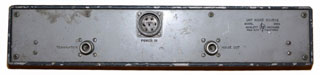
The
8411 fit on a shelf in the upper left the rear panel. On the
upper right of the rear panel there are two APC connectors for
the reference line. If the electrical length of the DUT +
the return coax was too long you could add a longer reference
line here to balance the phase.
the 8412
Phase Magnitude Display CRT was one of a number of displays that
plugged into the 8410, . This was the display of choice
for looking at gain or loss vs. frequency in real time.
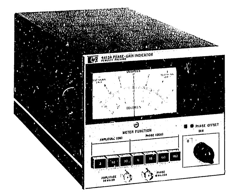
8413
Phase Gain Indicator meter might be useful if you wanted to get
more resolution in a manual measurement because you could expand
the meter scales.
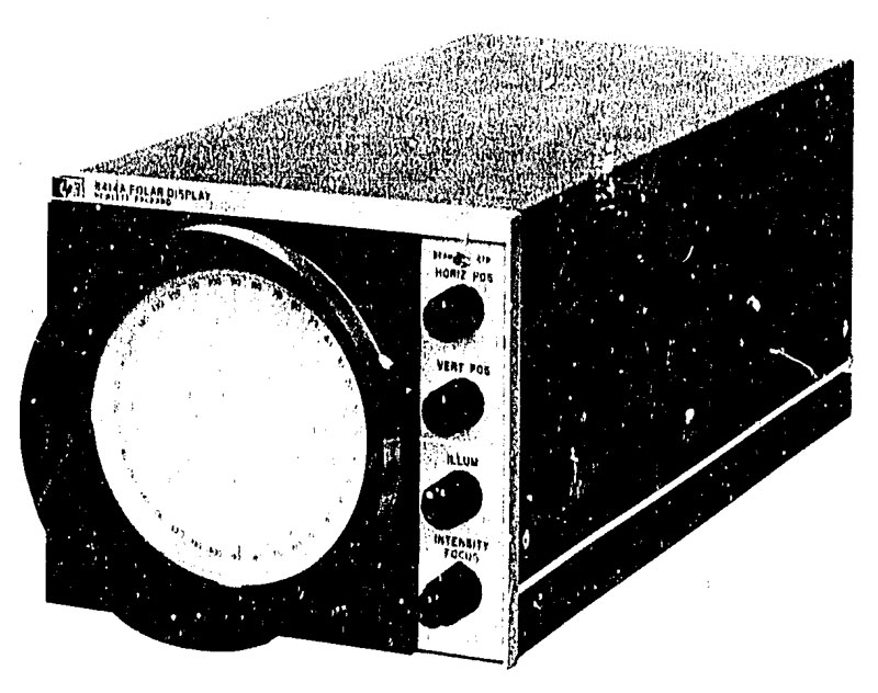
The 8414 Polar Display CRT is
the one that I felt was the most useful. There were Smith
Chart overlays made with a number of different
magnifications. One was the normal Smith chart, one was
magnified and the other was a wide angle. You could also
correct for the reflection coupler directivity by using a
sliding load.
Sliding Load
As one person pumped the sliding load back and forth you could
adjust the IF attenuation on the 8410 and the X and Y position
controls on the 8414 so that the dot was on a big circle
centered on the CRT. If you pressed the zero button after
this you would see that the dot was not in the center.
This was a manual way to correct for the directivity of
the reflection coupler. In automated NA systems you just
move the sliding load and then the system tests at all the
scheduled frequencies, then move it again, etc.
The 8418 Auxiliary
Power Supply could be used if you wanted to have two displays
like both the 8412 and 8414. There was an option for the
8414 that grounded both channels just like the zero push button
on the front panel. This allowed the two DVMs to read the
"zero" position of the spot.
Early automated systems had a problem in that the A/D
converters in the 8412 (I think this is the one but not sure)
were not so good. The fix was to use the 8414 and feed the
X and Y outputs to a good digital volt meter. Older
systems used the 59313A 4-channel A/D Converter.
There were a number of test sets all of which had reference and
test outputs that matched the reference and test input
mechanical locations on the 8411.
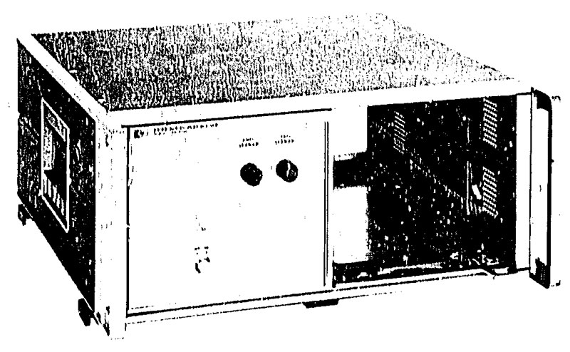
The 8740
is a DC to 12.4 GHz transmission test set that would be used
with the 11605 Flexible Arm that was made up of rotary joints
and hard lines. If you used your own coax to complete the
transmission path you might also need to add a longer reference
coax line on the back of the transmission test set in order to
be able to balance the phase plots (only if you were concerned
with phase linearity).
The 8741
is a 0.1 to 2 GHz Reflection test set and the 8742 is a 2 to
12.4 Ghz Reflection test set.
8742 is a 2 to 12.4 Ghz Reflection Test Unit very
similar to the 8741 except for frequency coverage.
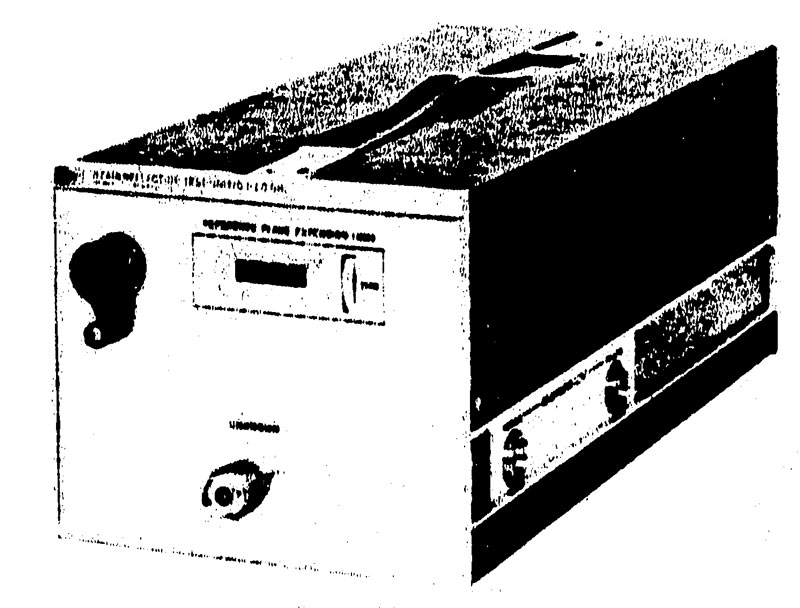
The 8743
is a 2 to 12.4 Ghz Transmission and Reflection test set (Option
-018 goes to 18 GHz) but has no provision for reverse
S-parameters so you need to physically reverse the device under
test to measure them. In the upper left is the crank to
control the electrical length. Remember that the 8410 is a
analog instrument, there is no microcontroller in it.
Microcontroller based network analyzers replaced the mechanical
line streacher with math on the phase data.
The 8745 S-Parameter Test Set is a
0.1 to 2 GHz S-Parameter test set that can measure all 4
S-Prameters with one insertion of the test device. This
allowed complete testing transistors with a single insertion and
without reversing the test fixture. The transmission return
hard line and rotary joint return arm for the 8745 was the
11604. There also was a rack width DC power supply for
biasing transistors that may have been the 8714.
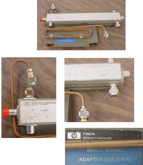
11607A
Small Signal Adapter - an external coupler to allow the reference
signal to be large and the test signal to be small. AFAICR
Good for testing devices that need a small signal so as not to be
driven into non linear operation. Note: most semiconductors
should be driver at -20 dBm or lower.
8746 S-Parameter Test Set covers 0.5-12.4 GHz and has a
built in 0 to 70 dB step attenuator (10 dB steps).
The 11605
is the Flexible Line used to complete the transmission return
path, or you can use your own coax cable if phase is not
important. This line is awckward to use because it has
limited degrees of freedom. This line does not have the
phase changes associated with many flexible coax lines.
8409 Network Analyzer
This was a computer controlled system based on the
8410. We rolled our own versions of this system with
improvements in the software and calibration methods.
See HP
Journal March 1967.
I have read on the internet that the 8409S contained:
8620C based sweeper (although later ones had an 8350 sweeper)
3335A generator - to supply the local oscillator to the 8411
harmonic converter or to drive the Synchronizer???
8709A Synchronizer - to force the microwave generator (operating
in single frequency mode) to be on the correct frequency
9845C Calculator with HP-IB interface
2 each 'S' parameter test sets
a switching box that used a single 8411 sampler
the 8410C with the auxiliary display holder
2 or more 6 foot tall rack cabinets
A computer controlled 8410 system was described in the Feb
1970 issue of the HP Journal. There was a small
business setup in Palo Alto that had this system and we would
bring microwave transistors to them and get S-Parameter data for
each serial number transistor.
AP App Note 221a (an221a.pdf)
describes a two rack plus 9845T desktop calculator (HP called them
calculators because there were purchasing restrictions on
"computers") on it's own separate stand, so it took up the space
of a three rack system. It also used two 8620C sweepers one
for each to the two test sets. This is better than the
multiple BWO (Backward Wave Oscillator) system, but eventually
after using the 8350B the ultimate answer was to use a synthesized
source. This app note talks about using an HP 59313A Analog
to Digital Converter. 11863D was the software package for
this app note.
This system used the Source Phase Lock subsystem that consisted of
an HP 3335A Synthisizer/Level Generator which even today is the
instrument used to calibrate other instruments even though it's
long obsolete. It covers 200 Hz to 80 MHz in steps of 0.001
Hz and an amplitude range of -86.98dBm to +13.01dBm in 0.01dB
steps. The output of this synth was fed as the LO for the HP
8411 Harmonic Mixer. The output went through an HP 10515A
doubler and an HP 8447C RF amp then a 140 MHz band pass
filter. The HP 8709A Option H17 Synchronizer took the IF out
of the 8411 and drove the FM input of the sweeper. The 8411A
Opt 018 allowed switching between normal stand alone operation
(without all this extra equipment) or the Source Lock subsystem.
The problem with this is that there's a huge amount of phase noise
on the output of both the 8620C and the 8350B sweepers.
This system was found to have some problems. One was that
the same frequency needs to be tested many times. For
example during calibration of using a short, open and load then
during the testing of the DUT for S21, S11, S12 & S22.
The results of all these tests are combined mathematically to get
the final results. If the RF source does not exactly repeat
each test frequency then the result is degraded. So instead
of a sweeper, first an EIP frequency counter was used to phase
lock the RF sweeper and later frequency synthesizers were
used. Another problem was the quality of the analog to
digital converters that were reading the 8414 Polar Display.
These were replaced with a system DVM that was both fast and
accurate.
In the Typical Results section of an221a they compare the 8409A
(without Source Phase Lock), 8409B (with Source Phase Lock) and
8542B (metrology system).
When measuring an air line the 8409A shows gain up to 0.3 dB
whereas the 8409B shows 0.04 dB loss. Air lines can be
embarrassing to measure.
Trivia: You can make a more accurate measurement of a low
VSWR using a scalar analyzer than with a network analyzer.
This required a special Wiltron bridge and an air line plus a
termination that's slightly off from 50.0 Ohms. When a swept
VSWR measurement is made over a wide enough frequency range
compared to the length of the precision air line, the trace has
small oscillations caused by the slightly off termination circling
the air link 50.00000 Ohm impedance. By finding the mean
trace you can get a more accurate measurement than that provided
by a standard network analyzer. I wonder if this could be
incorporated into the software of a NA?
Trivia: This reminds me that one way to correct for the S11
of a reflection test port is to use the 8414 Polar display and a
sliding load on the test port. One person pumps the sliding
load back and forth while another person uses the X and Y position
controls to center the circle on the display. Now when you
press the center button you are seeing the S11 of the test
port. Note: This is a manual test method. In an
automated system there's a relay that presses and holds the center
button and the ADCs for X and Y are read and stored so later when
measurements are made the "centered" values are used to find the
vector of the measurement.
Trivia: In an221 there's a footnote "APC-7 is a registered
trademark of Bunker-Ramo Corporation".
Trivia: There is no HP-IB port on the 8410.
We used various models of the HP RMB HP-IB
computers to drive these systems. The programs were
written in RMB.
HP Demo 8409 System
HP brought this two rack wide, maybe six foot high demo system
to Aertech
when we were on Polaris Drive in Mountain View. They had a
van with a special mechanism that would hold the system
horizontally while driving and the they could pull it out the
back and then tip of upright. AFAICR it had wheels and
could then it could be pushed around on flat surfaces.
The first generation 21xx computer that controlled the system
had core memory. The network analysis software was
pre-loaded and so all that was required to do the demo was to
jump to the start of the demo program. When the big wigs
went to lunch the salesman started a simulation of a Stanford v.
UC Berkeley football game. The "quarterback" could call
the play and they were something like:
1. Punt
2. Short run
3. Long run
4. short pass
5. long pass
4. Field goal
The result for each play was based on statistics of prior Stanford
v. UC games for those plays, maybe average value and a sigma that
were applied to a random number generator. The results had a
low probability of an interception. It was very realistic
and fun to play.
But the key thing was the beauty of a core memory remembering
where it was when powered down. When the power switch was
turned on it started up right where it left off. There was
no such thing as "booting". The Trimble Trimpack series of
GPS receivers use an internal battery and special chip that makes
the RAM chips act as though they were core memory. That's to
say when you power up a Trimpack GPS receiver it just comesup
running with all the data that it had when powered off. This
is a great time saver compared to other GPS receivers that may
take over 15 minutes to do a "cold start", i.e. a long time to
first fix.
There was a big effort to come up with integrated circuits that
contained magnetic memory (Wiki: Bubble
memory) so that this feature of core memory could be part
of computers that used RAM memory that goes blank when the power
is turned off. 3454939
Magnetic domain propagation device, Paul
C Michaelis, Bell
Labs, 1969-07-08, -
Modern (2022) Solid State Drives (Wiki)
are an attempt to lower the "boot" time of a computer.
Scalar Network Analyzers
Scalar analyzers work with magnitude only (no phase
information). This means for normal use they are not as
accurate as the Network Analyzers. But for metrology grade
testing they can be more accurate. This involves the use of
precision transmission lines and the use of loads that are
slightly different from 50 Ohms. Wiltron made the bridges,
air lines and loads for this type of testing, but it wasn't used
for normal component testing.
The 8755, 8756 and 8757 are
scalar analyzers that we typically used with the 8350B
sweeper. The 56 & 57 have two HP-IB ports on the back,
one to connect to the sweeper and the other to connect to a
computer. Much of the automatic test software that I wrote
in HP Rocky Mountain Basic would allow the sweeper to be connected
to either the computer directly or to the 56 or 57. When the
sweeper is connected to the 56 or 57 then all commands to it must
be passed through the 56 or 57. When the sweeper is
connected directly to the 56 or 57 manual operation of the system
is much more user friendly.
These analyzers were a big improvement on using couplers and
detectors with an HP 120 (later Tek 5104?) scope and grease
pencils to mark the scope face.
There are two modes of operation when combining a sweeper with one
of the HP Scalar Network Analyzers.
System Interface
----------------
In one mode the sweeper is connected to the System Interface HP-IB
connector and there is some functionality linking the two
instruments without a computer.
Note the HP SNAs require a 27.8 kHz square wave modulation on the
microwave signal, which is a built in feature of the 8350B or can
be done using an external modulator.
Also required is a 0 - 10 Volt sweep ramp.
Standard HP-IB Interface
-------------------------
There is also a standard HP-IB connector on the SNA that allows
computer control. In the systems I designed this was the
connector that was used with a computer and so any sweeper
equipped with an HP-IB connector could be used.
One feature of the RMB code used to control this system was a
check of the HP-IB connection status. For example, if you
loaded the software into an RMB computer and ran it without any
equipment connected it would prompt you to configure the HP-IB
address of each equipment and connect it. If later one of
the HP-IB cables was disconnected or failed that same prompt would
show up allowing the tech to figure out what was wrong and correct
it.
Also used one or more of the 8350B service HP-IB commands as part
of the above routine to know what options were in the 8350B.
This may be related to the power calibration.
History
---------
Here are some historical microwave test methods:
1) BWO sweepers with poor frequency calibration used with
absorption wave-meters which produced a notch at the set frequency
provided the test signal. http://www.prc68.com/I/RWR.shtml#TE
A tunnel or crystal detector driving an oscilloscope with a high
gain DC coupled input like the HP 120 http://www.prc68.com/I/TF_rack.html
If a VSWR measurement a Narda directional coupler and another
detector were also used.
A grease pencil would be used to draw a calibration line on the
scope.
A variable attenuator could be used to move the trace by the VWSR
(translated to return loss using the HP microwave cardboard slide
rule).
2) The storage normalizer was to replace the grease pencil but I
don't remember seeing more than one of them.
3) The scalar network analyzers (SNA) became the workhorses and we
had dozens of setups using the 8350B and 8756 or 8757 SNAs.
A good number of these with a computer.
These and the 8350B also support offset
sweeping which is needed for mixer testing.
4) The 8350B supports the use of an external detector to provide
power leveling. For many things this is OK, but for more
precise power control a computer can be added to either do point
by point power control (based on a calibration using a power
meter) or to measure the actual power at some number of points as
controlled by the leveling loop.
I have an HP System Key for use with HP 85015 System
Software. This worked with the 8756/8757 Scalar Network
Analyzers.
The system key is has an HP-IB connector.
Slotted Lines
Prior to the HP 8410 Network
Analyzer slotted lines were used to plot a Smith Chart of a
component. A typical setup would be:
CW Signal generator (1 kHz square wave modulation) - high quality
pad - slotted line (either coax or waveguide) - Device Under Test
(DUT).
The carriage on the slotted line has a detector feeding an HP 415
which is a very narrow band 1 KHz AC voltmeter.
By moving the carriage to the peak and adjusting the 415 to full
scale then moving the carriage to the null and noting the 415
reading and the carriage distance you get a data point.
If the 415 amplitude drops many tens of dB then the DUT has
excellent return loss (very low VSWR) and the data point is at the
center of the Smith Chart.
If the 415 amplitude drops a small number of dB then the data
point is not far inside the outer circle of the Smith Chart and
it's phase is the difference between the short null and the new
null normalized by the wavelength.
Note the distance between nulls is related to the wavelength of
the test signal and if the slotted line is long enough you can
measure the distance between adjacent short nulls to get a half
wavelength distance. Getting at least two nulls during the
short calibration is required. Since slotted lines are
typically 50 Ohm coax air lines they get longer as the test
frequencies get lower. Then come slab lines, two flat plates
with a rod halfway between them, then waveguides with a slot in
the center of the broad wall.
Calibration involves measuring a load and a short (the null
locations are the basis of Smith Chart rotation when the data
points are measured).
It can take the better part of a day to make a Smith Chart plot of
a DUT at 11 frequencies and much longer if you want to measure a
few DUTs to see what an average unit looks like to do a new
design.
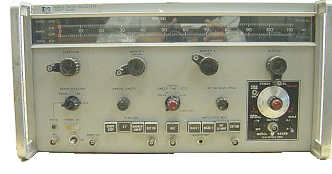
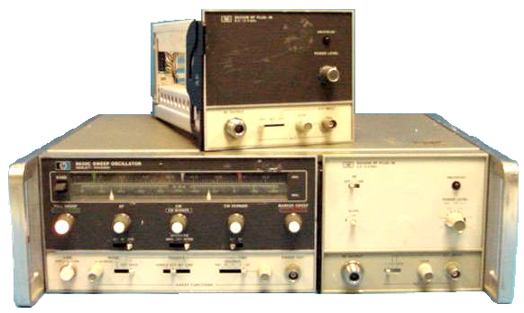
Sweepers
Early test setup using the 8410 was driven by octave
band HP 690 series sweep oscillators that used Backward Wave
Oscillators (BWO) in plug ins. To go with each plug in there
was a plastic ruler that snapped over the frequency pointers to
give you a rough idea of the frequency. But you would need a
wave meter (tunable cavity that puts a narrow suck out on the
scope display) in series with the RF setup so you could really
know the frequency. The HP BWO sweeper was about 1/3 the
size and weight as the Alfred unit
that it replaced (a true boat anchor). HP had a combiner box
that would hold three of the plug ins and a controller plug in
that went into the 690 series main frame.
Microwave detectors were used to convert the microwave signal into
a DC coupled low frequency signal that was fed to an
oscilloscope. The HP 120 scope was used for many years and
later I switched to the TEK
5000 series scopes which were purchased as three parts, the
mainframe, the vertical plug-ins and the time base plug-in.
By doing that each PO would be under the dollar limit so no high
level approval would be needed.
Tek Low Cost Scope
Model Description
5103N Main Frame
5A13 differential 2MHz
5A14 Four Trace plug-in, 1 MHz
5A15 single 2MHz 1mV-5V/div
5A18 dual 2MHz
5A19 differential 2MHz 1mV
5A20 differential 1MHz 50uV
5A21 differential/current probe amp 1MHz
5A22 differential 1MHz 10uV
5A23 single 1.5MHz
5A24 single 2MHz 50 mV-1 V/div w/prototyping
area
5A26 dual differential amp 1MHz
5A24N V. Plug-in
5A38 dual 35MHz
5A45 single 60MHz
5A48 dual 50MHz 1mV/div
5B10N timebase 100ns-5s/div
5B12 dual timebase 100ns-5s/div
5B13 timebase to 1us/div
5B25 digitizer time base, used w/5223
5B31 digital delay timebase
5B40 timebase 50MHz 10ns-5s/div
5B42 delaying timebase 50MHz 10ns-5s/div
5B44 dual timebase to 50ns/div
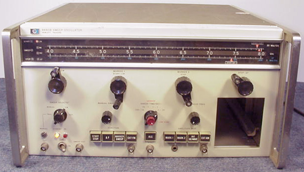
Then the 8690 and 8690B mainframes, 8693A bwo plug-in.. This
combination allowed sweeping across a frequency range covered by
the three such as 2 to 4 then 4 to 8 then 8 to 12.4 giving a 2 to
12.4 Ghz sweep.
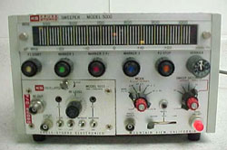
Later the Kruse Stork Model
5000 (later Systron Donner) on highway 101 in
Mountain View came out with a small solid state sweeper
that could sweep 1 to 18 GHz using a combiner box similar
to the HP unit but much smaller and with leveling.
Kruse Stork Patents: 3397365
- 1967, Oscillator with separate voltage controls for narrow and
wide tuning - 3377568
-
1968,
Voltage
Tuned
Oscillator
3416100
- 1968, Voltage Tuned oscillator with resistive and capacitive
tuning diodes (Varactor and PIN diodes)
Later HP came out with the 8620
then the 8350 sweepers which we used for all kinds of microwave
testing.
From somewhere else:
86220A 0.01 to 1.3 GHz 86222B 0.01 to 2.4 GHz 86230B 1.8 to 4.2 GHz 86235A 1.7 to 4.3 GHz 86240D 5.9 to 9.0 GHz 86241A 3.2 to 6.5 GHz 86245A 5.8 to 6.5 GHZ 86260A 12.4 to 18.0 GHz 10 mW 86290B 2.0 to 18.6 GHz
8350B
Mainframe
This was the workhorse at Aertech/TRW Microwave/FEI Microwave for
production testing of all kinds of products. Mostly used
with Scalar Network Analyzers but sometimes with 8410 Vector
Network Analyzers, like for tuning the RWR
modules.
The 8350B has support for mixer testing where two 8350 boxes
can sweep with a constant offset (the mixer IF frequency).
This feature was critical for mixer testing and was not
supported by otherwise competitive sweepers.
There was a problem with automated systems based on the 8350
(and all the earlier signal sources) in that when you programmed
the microwave source to go back to some frequency it would be
off just a little. Since an Network Analyzer error
corrected measurement required measuring a number of standards
and then the device under test a number of times, and then
combining all the results to remove the errors any change in the
frequency would introduce an error. By using and EIP 575 (EIP App
Note 5 "Using the EIP 575B/578B Source Locking Counters
with the HP 8350B and Its family of Plug-ins") Source Locking
Microwave counter you could program the source and counter to a
frequency and the counter would output a DC feedback voltage
that could be fed into the 8350 DC coupled FM modulation input
to frequency lock the source. This way you would get the
same test frequency every time making the test results more
accurate. Modern network analyzers use a synthesized
source so this is no longer an issue. But the cost for the
EIP counter and the 8350 sig gen was much lower than the cost of
a synth.
I don't remember trying the EIP + 8350 combination for the mixer
spur test system, I think for that application the synth was
needed to get the phase noise down low enough.
There are HP-IB (IEE 488) commands used for service that are
not listed in the user programming manual that are useful for
production automated testing.
Plug-Ins - came in suffix letters A/B/C/? and with option
numbers for things like a built-in 0 - 70 dB step attenuator. 83522A 0.01 to 2.4 Ghz 20 mW 83525A 0.01 to 8.4 GHz 83540B 2.0 to 8.4 GHz 40 mW 83545A 5.9 to 12.4 GHz 83550A 8.0 to 20.0 GHz 83554A 26.5 to 40.0 GHz 83570A 10.0 to 26.5 GHz 83572C 26.5 to 40.0 GHz 83590A 2.0 to 20.0 GHz 83592C 0.01 to 20.0 GHz 83594A 2.0 to 26.5 GHz 83595A 0.01 to 26.5 GHz 83596A 2.4 to 40.0 GHz 83597A 0.01 to 40.0 GHz 11869A adapter allows use of 86200 series Plug-Ins
Synthesizers
An early attempt to build an
automated mixer test system was based on using a pair of HP 8350B
sweepers. The mixer offset cable was not used since the HP
RMB Computer would set the frequency of both sweepers. An HP
8566B Spectrum Analyzer was used to look at the mixer
output. This system did not work because the phase noise of
both of the sweepers spread the output signal so much that it was
very difficult to measure. The solution was to use a pair of
synthesizers and to connect the 10 Mhz reference output from
whichever instrument had the best internal oscillator to the other
two so all three ( 2 - synthesizers, 1-spectrum analyzer) were
using the same reference. Even if the referenceis off all
three will see a signal at the same indicated frequency.
This allows the use of very narrow IF bandwidth in the SA and
either zero span or very narrow span instead of waiting for a full
sweep, greatly reducing the time to make a single
measurement. The down side of this is that synthesizers cost
maybe 10 times what sweepers cost for the same frequency and power
capability.
Spectrum Analyzers
The most often used model was the HP
8566B. Saw one at the HP Santa Clara facility that was
running water fall software and the sweep was covering all of the
amateur 2 meter band. When a repeater was keyed you could
see vertical lines for both the input and output frequency that
would start and stop at the same time (vertical axis). I
think this was an IBasic program running inside the SA, if
you know more about it let me know.
My home SA is the HP 4395A
which is a "combo" instrument from HP Japan, i.e. it can be a
Network Analyzer (NA), or Spectrum Analyzer (SA) or Impedance
Analyzer (needs optional firmware) (ZA). The prior combo box
was the HP 4195A which used conventional analog circuits, but the
4395A uses a digital IF system that allows it to display much
faster, also allows displaying true power rather than a signal's
peak, and allows true 1 Hz RBW measurements.
While working on a proposal for some satellite hardware I studied
measuring non harmonically related spur detection. The idea
was that we would need to use a spectrum analyzer with a vary
narrow resolution bandwidth in order to detect very weak
signals. This requires an automated setup working for many
many hours is not days. The HP 70000 series was the fastest
way to make the test.
Model
Description
Operation
Service
70000
System
UG_70900-90286
70900-90314
70001
Mainframe
70001-90060
Inst_70001-90021
SA
100 Hz - 2.9 GHz SA
HP 70004A color display
70904A RF section
70902A IF section
70900A LO module
Agilent app note AN64-1C
has a lot of good information about power measurements including
some history. Alos see Chooosing the right power meter and
sensor 5968-7150E.
Bolometers - measure power based on resistance
change caused by temperature change from RF heating.
Most accurate non NIST sensor type.
Barretter - A thin wire (might be a 10 mA fuse)
is one type of Bolometer with a positive temperature
coefficient. Thermister - semiconductor device with negative
temperature coefficient. By applying DC power to the
thermistor when no RF is present and then reducing the DC power
to keep the thermister at the same resistance the reduction in
DC power allows determining the amount of RF power that's
heating the thermister. There is also another thremister
in the sensor to compensate for ambient temperature. The
478A and 8478B are this type of sensor.
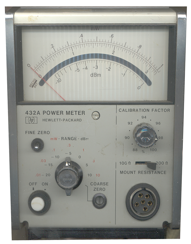
Since NIST will only calibrate Thermister type power sensors
(neither Thermocouple nor diode sensors are NIST traceable)
the 432A Power Meter is still a current model number because
it allows the most precise power measurement. The
related thremister sensors are also current model numbers.
Thermocouple - More sensitive than bolometers and have DC
out proportional to RF power in, i.e. square law detection.
Introduced in 1974. But since there is no longer any DC
power substution they need a 50 MHz reference power for
operational calibration. The 8481A is of this type.
Diode - Offer -70 to +20 dBm dynamic range in a single
sensor, but the peak power level needs to be below -20 dBm in
order to get correct results when measuring complex
waveforms. The -20 to +20 dBm range is good only for CW
signals. To measure non CW singals with average powers in
the -20 to +20 range use a thermocouple type sensor. In
order to have the 50 MHz calibration about in the center of the
power range a special 30 dB attenuator that's optimized for use
at 50 MHz is inserted between the sensor and the 50 MHz cal
port.
In 1975 the 8484A diode sensor was introduced. This was a
single Schottky diode that has a small error when the signal has
even order harmonic distortion (the + signal is not the same as
the - signal and the diode only detects one side).
A newer type based on GaAs material and Molecular Beam Epitaxy
(MBE is avery expensive process). These are the 8481D
series sensors and they use two diodes to correct the even order
harmonic problem and add a number of benefits related to
balance. Much higher output than the single Schottky diode
type because of the improved materials. The power range is
still -70 to +20 dBm.
E Series Sensors - These combine the GaAs dual
diode sensor with a EEPROM in the sensor to automatically load
the cal data into the power meter.
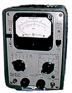
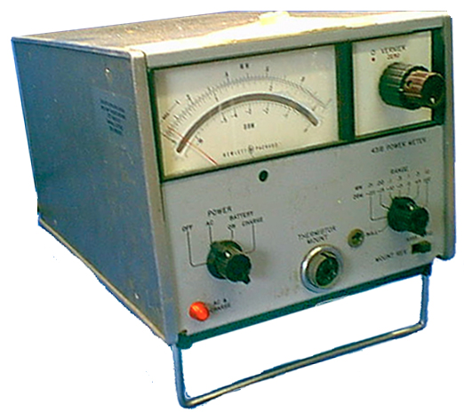
430A/B/C
Tube type
431A/B/C USM-260
Solid State
Manual Operation
introduces auto
temp compensation
with 10 kHz ref
Solid State
Manual Operation
A analog meter
B Digital meter
no 50 MHz cal reqd
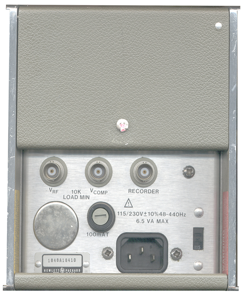
old cable Hi
Precision (0.2%)
Vref & Vcomp out
for highest accuracy
DC ref
Single Channel
IEEE-488
Sensor cal memory
50 MHz cal
new cable
438
Dual Channel
IEEE-488
Sensor cal memory
50 MHz cal
new cable
Power Meter Sensors & Cables
Old style, Bolometers
HP 478 & MX-7772/U Bolometer N(m)
10 MHz to 10 GHz
200 Ohms
30 mW max 5 W uS pulse max
.
8478B N(m)
0.01 to 18 GHz
8478B-11 APC-7
0.01 to 18 GHz
Waveguide Bolometers:
S478A 2.6 to 3.95 GHz
G478A 3.95 to 5.85
J478A 5.3 to 8.2
H478A 7.05 to 10
X478A 8.2 to 12.4
M478A 10 to 15
P478A 12.4 to 18
K478A 18 to 26.5
R478A 26.5 to 40
New Style, Thermocouple
Model FS Power
Range Freq
HP 8481A -20 to +20 dBm 10 Mhz to 18 GHz
HP 8482A -20 to +20 dBm 100 kHz to 4.2 GHz
HP 8483A -20 to +20 dBm 100 kHz to 2 GHz
HP 8481H 0 to + 35 dBm 10 Mhz to 18 GHz
HP 8482H 0 to + 35 dBm 100 kHz to 4.2 GHz
HP 8484A -60 to -20


 The 8410
would display the Smith chart in real time allowing
tuning. The 8411 Harmonic Converter has a reference and
test input port and inside a variable frequency oscillator
generating harmonics way up into the microwave region that acted
as the local oscillator to the reference and test mixers.
The down converted Intermediate Frequency was fed back into the
8410 main frame. The socket for the 8411 umbilical cord
could be on the front or optionally n the rear panel of the
8410. The 8407 is a lower frequency analyzer that covers
100 kHz to 110 Mhz. There is no separate frequency
converter, there are two direct inputs to the 8407.
The 8410
would display the Smith chart in real time allowing
tuning. The 8411 Harmonic Converter has a reference and
test input port and inside a variable frequency oscillator
generating harmonics way up into the microwave region that acted
as the local oscillator to the reference and test mixers.
The down converted Intermediate Frequency was fed back into the
8410 main frame. The socket for the 8411 umbilical cord
could be on the front or optionally n the rear panel of the
8410. The 8407 is a lower frequency analyzer that covers
100 kHz to 110 Mhz. There is no separate frequency
converter, there are two direct inputs to the 8407. 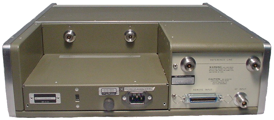 The
8411 fit on a shelf in the upper left the rear panel. On the
upper right of the rear panel there are two APC connectors for
the reference line. If the electrical length of the DUT +
the return coax was too long you could add a longer reference
line here to balance the phase.
The
8411 fit on a shelf in the upper left the rear panel. On the
upper right of the rear panel there are two APC connectors for
the reference line. If the electrical length of the DUT +
the return coax was too long you could add a longer reference
line here to balance the phase. 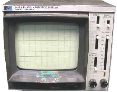 the 8412
Phase Magnitude Display CRT was one of a number of displays that
plugged into the 8410, . This was the display of choice
for looking at gain or loss vs. frequency in real time.
the 8412
Phase Magnitude Display CRT was one of a number of displays that
plugged into the 8410, . This was the display of choice
for looking at gain or loss vs. frequency in real time. 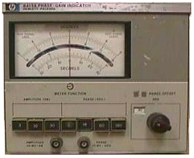 8413
Phase Gain Indicator meter might be useful if you wanted to get
more resolution in a manual measurement because you could expand
the meter scales.
8413
Phase Gain Indicator meter might be useful if you wanted to get
more resolution in a manual measurement because you could expand
the meter scales.  The 8414 Polar Display CRT is
the one that I felt was the most useful. There were Smith
Chart overlays made with a number of different
magnifications. One was the normal Smith chart, one was
magnified and the other was a wide angle. You could also
correct for the reflection coupler directivity by using a
sliding load.
The 8414 Polar Display CRT is
the one that I felt was the most useful. There were Smith
Chart overlays made with a number of different
magnifications. One was the normal Smith chart, one was
magnified and the other was a wide angle. You could also
correct for the reflection coupler directivity by using a
sliding load. 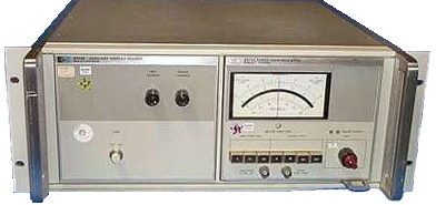 The 8418 Auxiliary
Power Supply could be used if you wanted to have two displays
like both the 8412 and 8414. There was an option for the
8414 that grounded both channels just like the zero push button
on the front panel. This allowed the two DVMs to read the
"zero" position of the spot.
The 8418 Auxiliary
Power Supply could be used if you wanted to have two displays
like both the 8412 and 8414. There was an option for the
8414 that grounded both channels just like the zero push button
on the front panel. This allowed the two DVMs to read the
"zero" position of the spot. 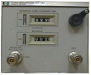 The 8740
is a DC to 12.4 GHz transmission test set that would be used
with the 11605 Flexible Arm that was made up of rotary joints
and hard lines. If you used your own coax to complete the
transmission path you might also need to add a longer reference
coax line on the back of the transmission test set in order to
be able to balance the phase plots (only if you were concerned
with phase linearity).
The 8740
is a DC to 12.4 GHz transmission test set that would be used
with the 11605 Flexible Arm that was made up of rotary joints
and hard lines. If you used your own coax to complete the
transmission path you might also need to add a longer reference
coax line on the back of the transmission test set in order to
be able to balance the phase plots (only if you were concerned
with phase linearity). 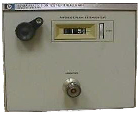 The 8741
is a 0.1 to 2 GHz Reflection test set and the 8742 is a 2 to
12.4 Ghz Reflection test set.
The 8741
is a 0.1 to 2 GHz Reflection test set and the 8742 is a 2 to
12.4 Ghz Reflection test set.  The 8743
is a 2 to 12.4 Ghz Transmission and Reflection test set (Option
-018 goes to 18 GHz) but has no provision for reverse
S-parameters so you need to physically reverse the device under
test to measure them. In the upper left is the crank to
control the electrical length. Remember that the 8410 is a
analog instrument, there is no microcontroller in it.
Microcontroller based network analyzers replaced the mechanical
line streacher with math on the phase data.
The 8743
is a 2 to 12.4 Ghz Transmission and Reflection test set (Option
-018 goes to 18 GHz) but has no provision for reverse
S-parameters so you need to physically reverse the device under
test to measure them. In the upper left is the crank to
control the electrical length. Remember that the 8410 is a
analog instrument, there is no microcontroller in it.
Microcontroller based network analyzers replaced the mechanical
line streacher with math on the phase data. 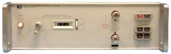


