AM-6536 / ALR-54
LAMPS Radar Warning Receiver Front-end
Brooke Clarke 2006 - 2016  |
 |
 |
| Connector
Face
lower left video amp removed. The upper left connector is a video input for the fifth amp |
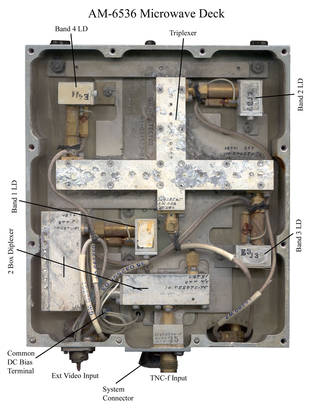
Microwave
Face
with major parts labeled. The first box after the input may be a Wilkinson power divider (Wiki). The box to it's left may be a high pass filter (Wiki) |
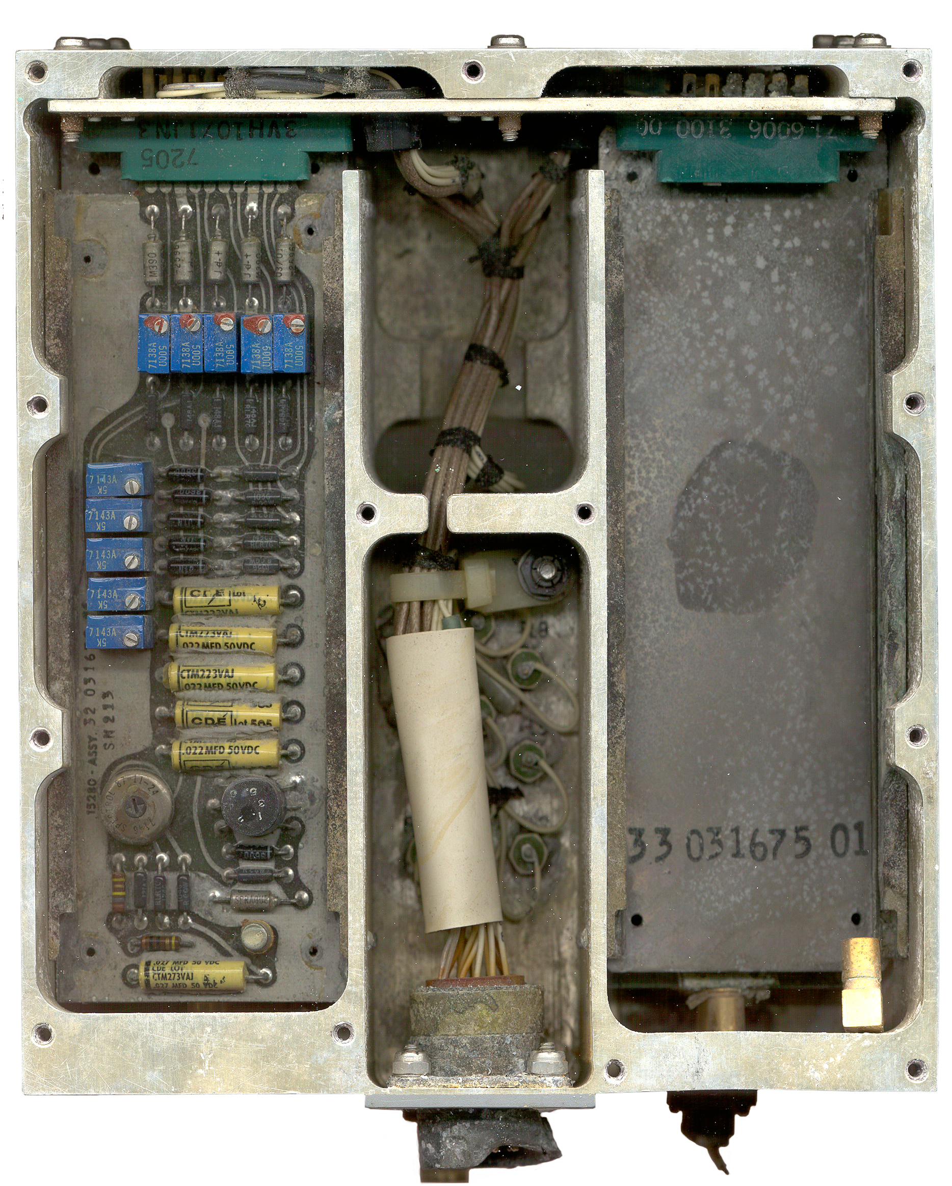
Video
Face with the right top video amp removed |
 |
||
| Video PCB |
||
Background
Radar Warning Receivers
AM-6536 Microwave Signal Processing Box
Limiter Detectors
Video Amplifier
Related
Links
For microwave RWRs the frequency selection network consists of a multiplexer (in the case of the ALR-54 it has 4 outputs) that typically had 3 or 4 outputs each driving a Limiter-Detector (LD) followed by a video amp.
An airplane would have 4 of these boxes, one for the nose antenna, one for each of the two wing tip antennas and one for the tail antenna. So one plane might use 12 or 16 LDs. I'm not sure how many antennas are on the LAMPS helicopter. If you have a Jane's book with first generation LAMPS info I'd like to get a copy of the page.
For more see my RWR web page, Aertech web page.
The detector has 4 main parts:
This box contains five video amps, four for the LDs and one gets it's input from what may have been a TNC-m connector. What was the source of the video? Tell Me
To measure the Noise Figure of the log video see the Microwave Test Equipment web page.
Radar Warning Receivers
AM-6536 Microwave Signal Processing Box
Limiter Detectors
Video Amplifier
Related
Links
Background
I recently found this RWR box on
eBay and could recognize the Limiter Detectors as those that I
designed. I did not know they were used in the first
generation LAMPS I (Wiki: Light
Airborne Multipurpose System, SH-2
SeaSprite). This particular unit has seen some
extreme abuse that might include salt atmosphere for 30 years
with one cover removed and in addition to physically breaking
the connectors. It's interesting that the gold plated
parts of the limiter detectors look as good as the day they
were made. The filters that may be made with silver
plating on aluminum are pretty grungy.
Radar Warning Receivers
The early RWRs were what's called "crystal video" types. Essentially they are crystal radios. That's to say the antenna feeds a frequency selection network which feeds a crystal detector. After the detector is a video amplifier (usually it's a logging video amp) and on to the processing circuitry. There is no local oscillator, no mixer, no IF amp. This makes for a lower cost receiver although one that's not as sensitive.For microwave RWRs the frequency selection network consists of a multiplexer (in the case of the ALR-54 it has 4 outputs) that typically had 3 or 4 outputs each driving a Limiter-Detector (LD) followed by a video amp.
An airplane would have 4 of these boxes, one for the nose antenna, one for each of the two wing tip antennas and one for the tail antenna. So one plane might use 12 or 16 LDs. I'm not sure how many antennas are on the LAMPS helicopter. If you have a Jane's book with first generation LAMPS info I'd like to get a copy of the page.
For more see my RWR web page, Aertech web page.
AM-6536 Microwave Signal Processing Box (? official name) Tell Me
6.00" wide x 6 13/16" deep x
3.25" high box where one of the lids is 1/8" thick and has the
mounting holes. Typically 4 per airplane, but I don't
know about on choppers. Labels:
The plate holding the microwave parts is labeled:
Quad Detector
???? 41-031530-0
| AM-6536/ALR-54 CONTR N00019-72-C-0044 D.A. 15280 P/N 31-031394-01 MFR 15280 T.M. <blank> |
This item warranted for
180 days after delivery Warranty Terminates _______<blank>________ Contract No. N00019s-72-C-0044 <Itek Logo> |
The plate holding the microwave parts is labeled:
Quad Detector
???? 41-031530-0
Input Connector
Although all the microwave cabling inside the box is SMA (0.141") coax, the input is a TNC-m connector. Note that BNC, TNC and type-N connectors all have identical mating parts and will mate between series but have different attachment nuts and threads/lugs. When 0.141" O.D. coax was first used the cables all had male ends and the boxes all used female panel jacks. The male connector was made by cutting a specified length of outer shield and insulation off the cable and slipping the male nut and hollow tube over the coax and soldering them together. The male pin is just the coax copper center conductor and the mating ground contact it the coax copper shield. This type of SMA connector has a very limited number of times it can be mated before you wear out the copper mating parts. It's great for the internal part of a system, but not so good for connections that will be cycled many times, hence the need for a more durable connector at the system level. TNC connectors have holes in the nut to allow safety wiring them and are commonly used in high vibration environments. On this box the TNC to SMA panel type adapter is held in an aluminum block, but I would have thought that the panel mount flange would be enough support, so why the extra support block? Tell MeMultiplexers
The microwave signal first goes to a diplexer made up of two boxes separated by a hard line, not connectors and then to the channel 1 LD. The other diplexer output drives a triplexer with the channel 2, 3 and 4 LDs on it's output. I seem to remember that most of the systems had only a triplexer so this system may have higher frequency coverage than the normal systems and the highest band is separated first. Why two boxes for the diplexer? Tell MeLimiter Detectors
At Aertech I developed the combined microwave Limiter Detector. The model numbers are A9X141, A9X142, A9X143 and A9X144. The A9X models were all special limiter detectors. And 141, etc. numbers were from a sequential book of special numbers Catalog parts had a frequency band code as part of the model number but on specials you can not tell anything about specs from the model number.Limiter
In order to get microwave frequency operation packaged diodes could not be used because of the package parasitic inductance. Instead a ribbon or mesh of gold was bonded from the input pin to the first diode, to the second diode and finally to the output of the limiter (which in a limiter detector was the input to the detector). The spacing of the diodes and the width of the mesh was designed to form a low pass circuit that would pass the highest microwave frequency. These could be tuned by hand using a stereo zoom microscope and a pin vise holding a sewing needle by moving the mesh up or down and adding a drop of black insulating epoxy to act and a dielectric forming a capacitor. This was done using the HP 8410 Vector Network Analyzer with a Smith Chart display plug-in.Detector
The LDs use Schottky diode detectors which need to be DC biased. Part of the microwave tuning of the LD is to determine the optimum bias current for that particular serial number unit. Too much bias and the output is too low and the VSWR is too good. Not enough bias and the output is high and the VSWR is too high. The bias current is set by a resistor in the box on the end of the LD that also contains the output connector and a solder terminal for the bias voltage. The AM-6536 has a common terminal used to feed all the LDs the system bias voltage.The detector has 4 main parts:
- Input diplexer that passes the desired microwave frequency band and looks like a short for the video output frequency band.
- Input matching circuit. These LDs use a single diode and one or two quarter wave transmission lines for impedance matching.
- The diode can be either shunt or series mounted depending on the design and output polarity, but I think these were shunt mount.
- Output diplexer that passes the video bandwidth and
looks like a short for the input frequency band.
Log Video Amplifiers
The log video amplifier was made by Itek IATI) using all discrete components. I think it's a log amp rather than a linear amp and that explains why 13 transistors are used, which would seem like too many for a linear type amplifier. The input is an SMB coax connection and the DC power supply input and output are on the 5 card edge connections. This amplifier has been highly optimized in terms of video bandwidth and noise as well as logging range.This box contains five video amps, four for the LDs and one gets it's input from what may have been a TNC-m connector. What was the source of the video? Tell Me
To measure the Noise Figure of the log video see the Microwave Test Equipment web page.
Video Post Amplifier
This board which is the same mechanical size ( 2.0" x 5.3" O.A.) as the video amplifier boards takes in the five signals and probably has gain and offset adjustments for each channel. Then all 5 signals are fed to the central signal processor box.External Connectors
J1
Is the multipin male circular military connector that has the DC inputs and the 5 channel video outputs. It's been smashed so badly that the contacts can not be counted so more on this later. Maybe 19 male pins marked 1 to 19.J2
Is the TNC-f microwave input connector that's fed typically from a cavity backed spiral wide band ECM antenna. These typically have a flat face a few inches in diameter, but some have a conical shape. Don't know for the ALR-54 which were used.J3
Is the TNC-m video input connector. What was this connected to? Tell MeRelated
Aertech (TRW Microwave, FEI Microwave)
ATI Universal Bench Test Kit -
Radar Warning Receivers - includes some info on Chaff.
Links
AN/ALQ
to
AN/ALT
- Equipment Listing - be sure to scroll all the way to
the "R" not the "Q".
FAS - SH-60 LAMPS MK III Seahawk - SH-2 Seasprite - Upgraded SH-60R rolls out -
FAS - SH-60 LAMPS MK III Seahawk - SH-2 Seasprite - Upgraded SH-60R rolls out -
Back to Brooke's PRC68, Military Electronics Information, Personal Home page
page created 30 Jun 2006.