HP 415 SWR Meters
& 200 Series Audio Oscillators
© Brooke Clarke,
N6GCE 2003 - 2022
Background
The 200 Series Audio
Oscillators are Related to the HP 415 SWR Meters
Model History
415A
415E Controls & Connectors
Operation
SWR Meter
Slotted Line
Smith Chart
HP
200 Series Audio Oscillators
Distortion
Analyzers
HP Slide rule Calculator
Patents
GR Products
Manuals
Links
Background
Back in the days of tube type equipment there was
an HP 415 SWR (Standing Wave Ratio) meter and there have been a
number of versions ending with the latest "E" model. This
instrument is a very narrow band 1 kHz attenuator and amplifier
and a precision rectifier. The relative amplitude of the 1
kHz signal can be read to scale ticks of 0.05 dB and interpolated
to 0.01 dB. There is also a scale for the original purpose
of reading SWR. The SWR scale was THE feature that separated
the HP instrument from the GR 1232A Tuned Amplifier and Null
Detector which took a lot of work when used to measure SWR.
It makes use of what some call the Hall Network (pdf)
"The only known commercial use of the Hall network is as a tunable
band-pass filter for the 1961 General Radio product, Type 1232-A
Tuned Amplifier and Null Detector (References 5 and 6). An
examination of the manual for this instrument reveals that all
capacitors are the same value. This product is still sold today by
IET Labs, Inc. (http://www.ietlabs.com/) as part of the GenRad
1620 Capacitance Bridge." Maybe Ken did not know about the
HP products that licensed the GR patent 2173427?
Note that if Full Scale is set on the "zero" range then when
reading down 10 dB on the 60 range you are reading a signal that's
down 70 dB.
The 415E is 6" high and 7 3/4" wide. This does not appear to
be a standard Rack Mount instrument
size.
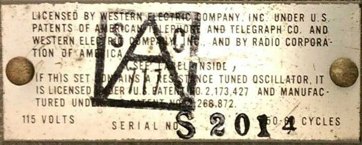
June 2022 noticed an HP 200C (HP
1943 Catalog pg 12) on eBay (TS-312/FSM-1) and the label on
the back referenced the same two patents as are on the HP 415A: 2173427 &
2268872.
It makes sense for the Hewlett patent 2268872, to appear on the
oscillator that makes use of it, but why on the 415 SWR meter
where only the GR patent (2173427) is being used? Maybe that
was part of a cross licensing agreement between HP and GR?
That would explain why the GR patent also appears on the HP audio
oscillator where it is not used.
Best guess:
TS-312/FSM-1
|
TM 11-2684
|
TS-312A/FSM-1
|
TM 11-2684A
|
| TS-312B/FSM-1 |
|
Let me know
about the FSM-1.
The HP 3550A Portable Test Set was in the 1965
Catalog and consisted of the 204B oscillator, 353A Patch
Panel, 403B Voltmeter all mounted in the 11046A portable
case. Intended for telephone related testing.
Maybe the FSM-1 was a similar test set?
The 200 Series Audio Oscillators are
Related to the HP 415 SWR Meters
I started this web page in 2003 because I like the HP
415E. The main reason is that I think of it as a AC
voltmeter with a very narrow pass band filter centered at 1
kHz. Because of kTBR noise (Wiki)
the narrower the instrument bandwidth the better the
signal/noise ratio (Wiki).
This also applies to radio receivers and spectrum
analyzers.
Another reason is that I spent many hours with an HP 415E and a
slotted line (Wiki)
plotting the impedance of the circulators used to make Tunnel Diode
Amplifiers (Wiki).
About a year later HP came out with the HP 8410 Vector
Network Analyzer that could show a real time plot of S11,
i.e. the impedance of the circulator so the SWR meter and
slotted line were relegated to the store room.
I searched for a patent on the HP 415 and for 19 years had no
luck. Notice that the 415
Model History section has no mention of any patents
because none of the HP 415 literature mentions any
patents. But then found it was patented by Herman Hosmer
Scott (Wiki)
(who was working for General Radio). He later started a
company that made High Fidelity stereo amplifiers under the
trade name H.H. Scott (Wiki).
That prompted me to get the HP 415A shown on this web page.
The HP 415A has a label that says: "Licensed by Western
Electric Company, Inc. Under U.S. patents of American Telephone
and Telegraph Co. and Western Electric Company, Inc. and by
Radio Corporation of America.
(See Label Inside)
If this set contains a Resistance Tuned Oscillator, it is
licensed under U. S. patent No. 2,173,427
and manufactured under U.S. patent No. 2,268,872."
I'm guessing that during W.W.II and for some years afterword
the first sentence was boiler plate credit to AT&T, WE and
RCA. But the second sentence is very specific to the HP
415 SWR meter. Since the HP 415 does not contain a
resistance tuned oscillator the 2173427 Hewlett patent that was
the basis of founding the company Hewlett-Packard (and probably
why Hewlett is the first mentioned name) that patent has no
relevance to the HP 415 SWR meters (Wiki: Wien
bridge oscillator, HP
HIstory, HP 200A).
It's the 2268872 patent by H.H. Scott working for General Radio
that's the heart of the HP 415 SWR meters. It is for what
I'd call an active filter (Wiki)
circuit that has the ability to implement either a very narrow
pass band filter (the HP 415 SWR meter, GR 760 Audio Analyzer,
&Etc) or a very narrow stop band filter, or an audio
oscillator.
It turns out that the HP200 series of audio oscillators make
use of GR patent 2268872 in the positive feedback portion of the
oscillator and the Hewlett 2173427 light bulb patent in the
negative feedback portion of the oscillator. While this
dependence on two patents is clear from the labels on the HP 200
series audio oscillators as well in the HP patent this is the
first time I've been aware of it.
415 Model History
HP Serial Number
to Mfg. date
HP
Journal
HP Journal Jan-Feb 1953 Vol 4 No. 5-6:
More
About -hp- Precision Directional Couplers - mentions
the 715A Klystron power supply and the 415A standing-wave
indicator.
HP Journal March 1955, Vol 6 No. 7:
A
New Standing Wave Indicator With an Expanded VSWR Scale -
The 415B. (the same issue has the 430C power meter).
HP Journal Oct 1955, Vol 7 No. 2: High -
Directivity
Coaxial Directional Couplers and Reflectometers - mentioned
416 Ratio Meter (see patent 2852743
HP
Journal July 1966 Vol 17,
Measuring Attenuation, SWR,
and Substitution Loss with a Low-Noise, High-Precision SWR Meter,
by Bradford G. Wolley
The 415E is pictured. The 415A dates from 1952.
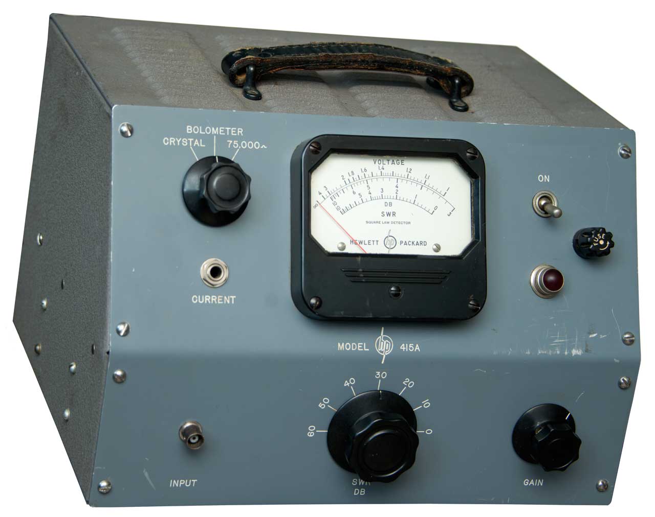
415A
This example is marked:
Licensed by Western Electric Company, Inc.
Under U.S. patents of American Telephone and
Telegraph Co. and Western Electric Company, Inc. and by
Radio Corporation of America.
(See Label Inside)
If this set contains a Resistance Tuned Oscillator, it is
licensed under U. S. patent No.
2,173,427
and manufactured under U.S. patent No. 2,268,872.
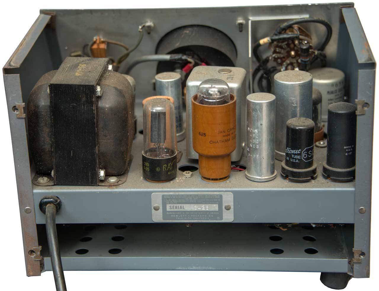
115 Volts 50 - 60
Cycles
Serial 3428
Manufactured in the United States of America
Hewlett-Packard Co.
Palo Alto, California (R)
|
IM-97/USM-37
Indicator, Standing Wave
Supply: 115V or 220V 1(phase) 60 (cycles)
A unit of indicator, standing wave AN/USM-37
Manufactured for
Navy Department - Bureau of Ships
By Contractor
Hewlett-Packard Company
Palo Alto California
Contract NObsr-64702
U.S. Property |
For the past 19 years (on and off) I've been trying to find the
HP patent for the 415 SWR meter. Today (2022 Apr 18) I
found a photo on an eBay ad for a 415A (it's on order) that
showed patent numbers 2268872 which is THE audio oscillator that
started HP. I don't understand why it's on the 415 SWR
meter? And another patent ending ....427. I could not find
any HP patents between 1941 and 1954 ending with 427. But
did find a photo of a USM-37 at NavyRadio.com
where, with a magnifying glass I made out patent 2173427
assigned to General Radio. The Inventor was H.H. Scott (Wiki).
PS I bought a new H.H. Scott stereo audio amplifier
and it had so much noise out into my Voice of the Theater speakers
that I traded it in for a McIntosh MC2505 (Wiki).
The Scott amp probably would be fine when used with Acoustic
Suspension loudspeakers (Wiki)
but not with efficient speakers like the Altec Lansing (Wiki)
Voice of
the Theater speakers.
GR made the 1232A Tuned Amplifier and Null Detector (IET:
manual)
based on thier patent 2268872. This requires tuning to the
desired frequency unlike the 415 which has a single pre-tuned
frequency. Also the 415 has a scale calibrated in SWR
whereas with the GR 1232A you need to manually calculate the SWR (
Wiki)
which involves taking two square roots which in the 1950s was not
trivial so the HP 415 was a great time saver.
The HP 415 SWR meter makes use of the General Radio active filter
patent 2173427 in order to get the narrow pass band which would be
difficult to get any other way. The HP 200 series of audio
ocillators (
Wiki) also make
use of the GR patent 2173427 in the positive feedback circuit that
determines the frequency of oscillation. Hewlett's patent
2268872 only applies to the negative feedback that stabilizes the
output level by means of the lamp in the input tube's cathode
circuit. HP licensed the GR patent for use in the 200 series
oscillator and 415 SWR meter and maybe other instruments yet
unknown to me. Note GR patent 2173426 was issued the same
day as 2173427 and is very similar and also describes the GR 760-A
Sound Analyzer, so maybe some early HP distortion analyzers are
also based on GR patents?
Let me know.
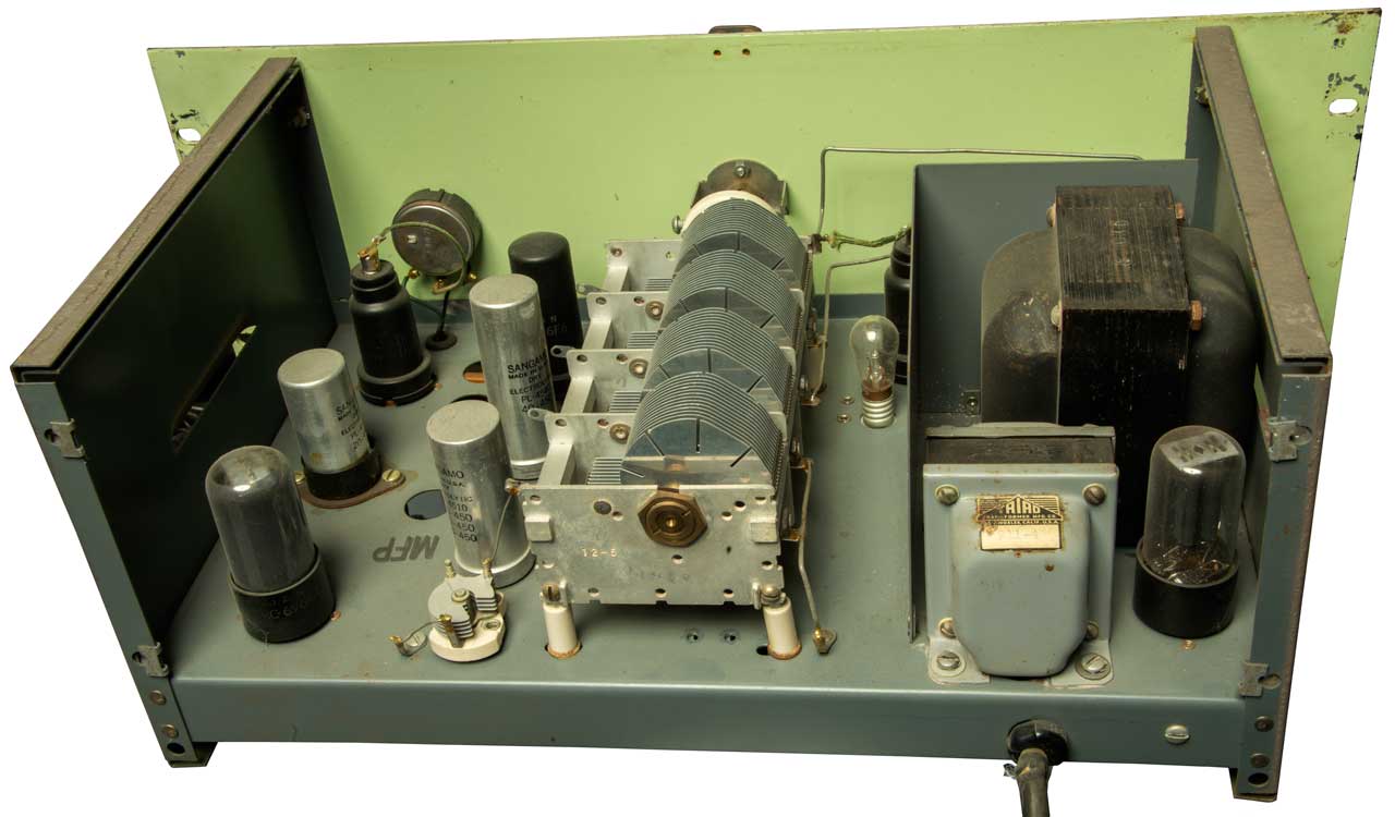
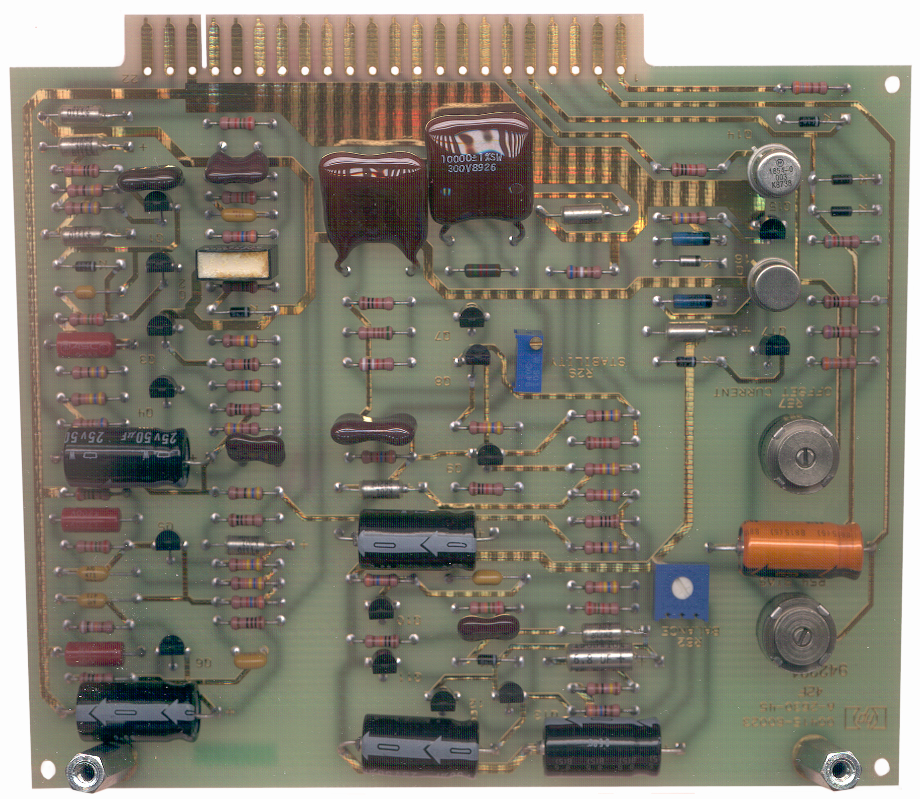
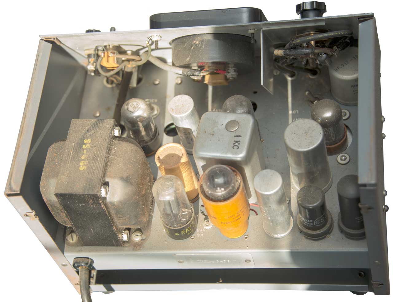
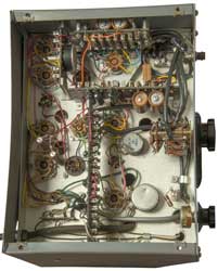
Fig 1

|
Fig 2
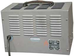 |
Fig 3
 |
Fig 4 Note aluminum can marked 1 kc.
In theory it could be unplugged and replaced with a
circuit for a different frequency.
 |
Fig 5 Terminal
Board construction
|
|
415E Controls & Connectors
Front Panel
The analog meter movement is a mirrored type where you look for
the reflection of your eye's pupil bisected by the needle and thus
eliminate parallax in the measurement. There is also a
mechanical meter zero pot. The correct way to use this is to
turn the pot in one direction so that the needle moves up scale
and and then comes back down scale and you stop turning when the
needle is over "2" on the expanded scale. If you over shoot,
do not turn the screw in the opposite direction, but rather,
continue turning and approach the zero position from up scale.
The POWER switch has positions for OFF, ON, (and for instruments
with the optional internal battery supply: Battery: ON, TEST and
CHARGE).
The INPUT switch has positions for XTAL IMPED: HIGH, LOW or BIASED
(+1.3 VDC on the center contact with 12.6 mA of current
capability) and BOLOMETER: 4.5 mA or 8.7 mA. To match a wide
variety of input sources. The HIGH position is also used for
signal sources that are not from a detector or power sensor.
The INPUT is a BNC(f) connector with the shell 50 Ohms above
ground.
The FREQ adjust pot allows the center frequency of the 415 to be
set to match the frequency of the source generator.
The BANDWIDTH control adjusts the width of the pass band and
therefore also controls the signal/noise ratio for faint input
signals. If the 415 is used with a sweeper this control
should be set fully CCW to increase the BW to allow for signal
variations as the sweep progresses. Also the amplifier
output should be used to drive a scope or chart recorder instead
of the recorder output since the latter has a low pass filter that
limits it's bandwidth.
The RANGE-DB control has an outer knob with positions for 0, 10,
20, 30, 40, 50, and 60 dB a very large dynamic range, and an inner
EXPAND knob with positions of: NORM, 0,
2, 4,
6 and 8 dB. By using the expanded
(red) scale positions you can read amplitude to 0.01 dB over the
full 60 dB range. On the 0-NORM range you can bring the
needle to full scale with an input signal between 0.120 VAC and
__?__.
Comparing the 34401 DVM with the 415E shows that the noise
bandwidth of the 34401 limits its use:
415E
|
34401A
|
FS 10 range
|
1.4 V
|
FS 20 range
|
140 mv
|
FS 30 range
|
14 mv
|
FS 40 range
|
1.4 mv
|
FS 50 range
|
0.01 mv*
|
FS 60 range
|
can not get signal this low
|
* 34401 is reading noise and 415E has a Full Scale reading.
The Gain & Vernier controls will bring the needle to Full
Scale with an input of more then 0.12 Volts up to more than 5
Volts.
Square Law
Note that the 415 reads 10*LOG(voltage ratio), this is called
"Square Law" and when the 415 is fed from a microwave detector
that has a low level signal at it's input the 415 will read the
same as a power meter because the detector has a "square law"
response. If you were trying to measure the dB difference in
two voltages you would normally use dB = 20 * LOG(voltage ratio),
but that's not what the 415 was designed to do.
Rear Panel
On the rear panel there is a BNC(f) RECORDER output that has a 0
to 1 VDC signal to drive a chart recorder and a pair of banana
jacks on the standard 3/4" centers that has the amplified 1 kHz
signal. There is a covered hole that can be used to change
the input connector from the front panel to the rear panel.
Operation
SWR Meter
I used the 415E for making microwave Smith Chart plots in
conjunction with a slotted line and for making attenuation and/or
gain measurements using a crystal detector. The 415E is very
good for both of these measurements and probably is the highest
dynamic range scalar measuring instrument around. It
would also work fine for making optical measurements with an
optical to DC converter.
A key feature is the narrow (slightly adjustable) bandwidth. Note
slotted screw pot at lower right of front panel. One article
says the Q is 25 to 35 centered at 1 kHz, so in the range of 40 to
28 Hz.
Side Bar: Lock-in Amplifiers (Wiki,
SRS
AN3) & Autocorrelators (Wiki)
I worked with an engineer from the UK many decades
ago. One of the jobs he worked on involved measuring
the impulse response of a steam powered electrical
generation plant. Since feeding the turbine an
impulse of steam would destroy pretty much everything some
other method was needed. He used an
Autocorrelator. This is a method even more advanced
than the Lock-in Amplifier. It involved a "T"
connection on the steam line where a piston that could be
used to make a very small change in the line pressure and
a very long digital signal.
Note that the 1 Hz Resolution Bandwidth of the HP 4395A
spectrum analyzer goes a long way to seeing very weak
signals.
Also see Microwave Test
Equipment\Hot-Cold Noise Source.
|
I'm considering using it to measure the output of magnetic field
sensors, where it's narrow noise bandwidth may greatly extend the
sensitivity of the sensor.
When a 5.04 k Ohm resistor is connected to the input and the range
set for Xtal Impedance High and both the gain and vernier knobs
are turned fully clockwise the meter reads 6.5 dB below full
scale. The manual addresses the theoretical KTBR noise (Wiki)
of a 5 k Ohm resistor and how the 4 dB noise figure of the 415E
will show up in the measurement. This shows how sensitive
the meter is.
Typical uses for the 415E are: SWR measurements using a slotted
line, Power measurements using a Bolometer (Wiki),
Relative power measurements using a crystal detector. In all
cases the source must have a 1 kHz square wave modulation.
Slotted Line
When a short is installed on the unknown port and the slotted
line (Wiki)
carriage is moved back and forth there should be a couple of
nulls a half wave apart. This means as the test frequency
gets lower the slotted line needs to get longer.
Record the location of a null. Install the Device Under
Test (DUT) and find the nearest null. The movement of the
null and it's direction (either toward the DUT or away from the
DUT) corresponds to be rotation on a Smith Chart (Wiki).
The SWR will determine the radial distance on the Smith
Chart. This is relative to the transmission line impedance
of the slotted line, typically 50 Ohms.
Slotted line in patent 2673963 below.
Smith Chart (Wiki)
Inspired by: The
Scariest Chart In Electrical Engineering, 39:43 -
The T5530
Tunnel Diode amplifier was redesigned to make it easier to
tune by using a Smith Chart. Which in turn was done by
measuring with the HP 415 and slotted line. I think that
the slotted like helps a lot in understanding how the Smith
Chart works.
The long hours needed to do manual Smith Charts was a
motivation to get the HP 8410 Vector Network Analyzer as
soon as it was available.
HP 200 Series
Audio Oscillators
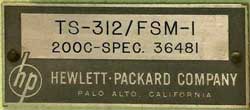
The label says:
|
TS-312/FSM-1
200C-Spec. 36481
Hewlett-Packard Company
Palo Alto, California
|
Let me know
what the FSM-1 is.
The 200CD Wide Range Oscillator with a military label: NSN:
6625-518-4659 AF Contract No. AF 36/600/12149 also has the
Hewlett patnet number 2268872 on the serial
number S-2014 label.
Fig 1 Front
 |
Fig 2 Back with patent licensing label
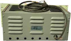 |
Fig 3 Back Inside
range switch behind power transformer
 |
Fig 4 Bottom either C4 or C10 missing under
bracket.
Cut white wire near line cord. So not complete.
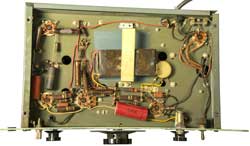 |
|
|
Distortion Analyzers
While the photo below is from an HP 330B Distortion Analyzer I
found on eBay, I expect the HP 300A and 320 Distortion Analyzers
also make use of the GR patent.
HP 330B Distortion Analyzer
Inside upper left corner of right side panel just above
the power transformer.
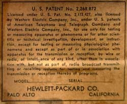
|
U.S. Patent No. 2268872
Licensed under U.S. Pat. No. 2173427, also licensed by
Western Electric Company, Inc., under U.S. patents of
American Telephone and Telegraph Company and Western
Electric Company, Inc., for use only for testing or
measuring apparatus or phenomena or for other scientific
or technical investigation, development, or instruction,
except for testing or measuring physiological phenomena
and except as part of or in association with apparatus for
the transmission or reception, by wire or radio, of
intelligence of any kind, other than in association with,
but not as part of, radio broadcast transmitting or
receiving systems for testing and measuring the
transmission or reception thereby of programs.
MODEL _________________ SERIAL _____________
Hewlett-Packard Co.
Palo Also California
Also see the Boonton Q-meter for
similar licensed by labeling.
|
|
HP
Journal Aug 1951, Vol 2 No. 12 Distortion
Measuring Equipment by Burnton Bauer: 300A, 320B, 330A
2418568
Frequency divider, Bauer
L Brunton, HP, 1947-04-08, - Fout =[Fin* (n+1)]/n
|
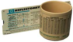
HP Slide rule Calculator
There were as many of these HP slide rules as there were
technicians and engineers or maybe even more. They were
mostly used with reflectometer setups for measuring reflection
coefficient and doing calculations related to that. During
the early years at Aertech we mostly used HP 690A and
8690A BWO sweepers.
|
Slide rule set at 14 dB RL = 1.5 VSWR.
That point also appears on the Allis Associates coffee
cup.
|
HP
App Note 183 "High Frequency swept Measurements", Dec 1978
is mentioned on the slide rule. The 8620 Sweeper is
featured along with the 11691D Directional Coupler and 423
Detector in the ALC loop, covering 0.1 to 18 GHz. Also
mentioned is the 8755 Scalar Network Analyzer. The 415E,
432A and 435A are also mentioned.
The Slide Rule description starts on pdf page 24 (doc pg 18).
Fig 19 shows the slide rule set for 1.5 SWR (14 dB) as in the
photo above. Mismatch Error Limits starts on pdf page 46
(doc pg 34).
App A covers 2 and 3 resistor power splitters.
App B covers Errors in Reflection Measurements.
App C covers Errors in Transmission Measurements & mentions
the 8750A Storage Normalizer that was supposed to replace grease
pencils.
While B and C do not mention S-Parameters the diagrams have the
look and feel of S-Parameters.
Patents
HP licensed the use of GR patent 217342 for the HP 200
series of audio oscillators and for the HP 415 SWR meter.
Both the HP 200 audio oscillator and the HP 415 SWR meter make use
of the GR patent. I think most people do not know that the
HP 200 series audio oscillators also depend on the GR
patent. Note H.H. Scott patents 2173426 and 2173427 were
issued the same day and are seminal in the filed of active
circuits.
|
2106785
Electric filter, Herbert
W Augustadt, Bell
Labs, 1938-02-01, 363/45;
330/202; 330/123 - balanced bridged-T?
|
|
2163403
Stabilized oscillator, Larned
A Meacham, Bell
Labs, 1939-06-20, 331/139;
331/140; 333/188; 331/66; 331/183; 333/17.1-
Bell Labs patent 2319965 explains how there's a better
way, such as 2173427.
The Bridge Stabilized Oscillator BSTJ (vol17-1938/articles/bstj17-4-574.pdf)
"The frequency controlling resonant element is used as one
arm of a Wheatstone resistance bridge."
|
|
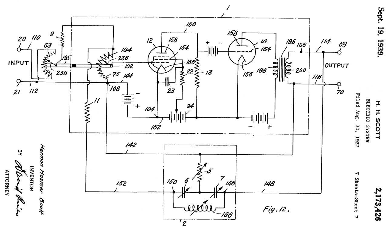
2173426
Electric system, Scott
Hermon Hosmer, (Wiki HH Scott: Company,
man),
General
Radio, 1939-09-19, 330/98;
330/85; 330/106; 330/109; 330/128; 333/171; 330/75;
330/96; 330/108; 330/127; 330/142; 333/172 -
"One of the objects of the present invention is to provide
a selective electrical circuit, the response of which may
be varied over wide frequency ranges without complicated
tuning and switching mechanisms and without any serious
shifts in the input and output impedances of the system or
its sensitivity. One of the important features of the
invention is that this result may be obtained without
necessitating the use of any inductances whatsoever, using
a frequency determining system which may consist of
resistances and condensers only. The frequency to which
such a system is selective can, accordingly, be varied by
merely varying resistances or condensers, or both
resistances and condensers."
This patent is on the label of the GR 760-A Sound
Analyzer, photos at left.
|

|
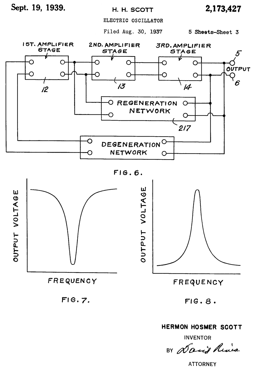
2173427
Electric oscillator, Scott
Hermon Hosmer, General
Radio, 1939-09-19, 331/138;
315/163; 330/86; 330/100; 330/106; 331/140; 331/142;
333/170; 330/104; 330/109; 331/141; 331/175 -
Filters in feedback networks.
On back of 415A and HP TS-312 (HP200C) -
"A chief object of this invention is to provide a simple
and satisfactory means of obtaining an oscillator which
will provide a sinusoidal output voltage, but which does
not contain any inductances as necessary circuit elements
in order to obtain this sinusoidal wave-form."
This patent is at the heart of both the HP 200 series
audio oscillators and the HP 415 SWR meter. That's
why it is printed on their labels.
|
|
2268872
Variable frequency oscillation generator, William
R Hewlett, HP
Inc, 1942-01-06 331/141;
331/183 - THE HP patent (Wiki)
with light bulb stabilization.
Makes use of positive feedback (GR patent) for determining
the frequency and negative feedback to reduce distortion
using a light bulb. This clearly is making use of
the GR patent 2173427 for frequency selection.
The level of oscillation is set to a low enough level, by
means of negative feedback, so that there's very little
distortion. It is kept at that low level even though
different tubes may be installed, or at different
temperatures, or over component drift over time &Etc.
by means of the non linear properties of the lamp (R3) in
the cathode circuit of tube (10).
See: A
real gem: HP's audio oscillator patent turns 60
- Model 200A (Wiki)
Photos at left of the TS-312/FSM-1 label which is an HP
200C audio oscillator.
|
|
2319965
Variable frequency bridge stabilized oscillator, Raymond
O Wise, Bell
Labs, 1943-05-25, 331/142;
331/176; 331/183; 66/172E -
Mentions:
2163403,
2106785,
2173427, H.H. Scott
Called by the Oliver/HP patent 2852675 |
|
2583649
Modified wien-bridge oscillator, William
R Hewlett, HP,
1952-01-29, 331/141 - to extend upper and lower
frequency limits. Calls the same patents as 2583943. |

|
2583943
Modified wien-bridge oscillator, William
R Hewlett, HP,
1952-01-29, 331/141 - to extend upper and lower
frequency limits.
Calls:
|
2072946
Harmonic analyzer, Paul
O Farnham, RCA,
1937-03-09, 333/171 -
this is an RCRCRC phase delay circuit, not an
active filter.
|
|
2093665
Star and delta connection of impedances, Tellegen
Bernardus Do Hubertus, RCA,
1937-09-21 333/171; 330/176; 333/170;
333/216 - various circuits including
bridged-T circuits, but no active filters.
|
|
GB524314 Improvements in and
relating to thermionic valve oscillators and
amplifiers, RCRCRC
|
|
2268872 THE Hewlett patent
|
|
2298177
Electric filter circuit, Scott
Hermon Hosmer, GR,
1942-10-06, 333/171 -
active RCRCRC
|
|
2354141
Universal resistance capacitance filter, Ellison
S Purington, RCA,
1944-07-18, 333/170 -
bridged-T passive
|
|
2444084
Resistance-capacitance oscillator, Artzt
Maurice, RCA,
1948-06-29, 331/136; 331/144; 331/141 -
|
|
2446821
Resistance-capacitance tuned oscillator, Gassel
William, Gritz
Henry, Philco
Ford, 1948-08-10, 331/135 -
|
|
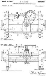 |
2673963
Ultrahigh-frequency measuring apparatus, David
Packard, HP, 1954-03-30, 324/645 - 809 (USM-37D) Universal
Carriage
This carriage can be equipped with waveguide or coax lines
to cover different frequency ranges.
Model
|
Impedance
Ohms
|
Frequency
|
Connectors
|
805A
|
50
|
500 - 4000 MHz
|
N
|
805B
|
43.6
|
500 - 4000 MHz
|
7/8"
|
806B
|
50
|
3 - 12 GHz
|
N
|
* 805A is a long slab line two parallel grounds with a rod
center conductor.
|

|
2852675
Modified Wien bridge oscillator, Bernard
M Oliver (Wiki),
HP,
1958-09-16, 331/141;
330/109; 330/119; 330/82; 330/110; 330/121 -
HP
Journal Feb.1956 Vol 7 No. 6 - 201C, 200J
& 202C
Balanced R-C Oscillator circuit B.M. Oliver. |
|
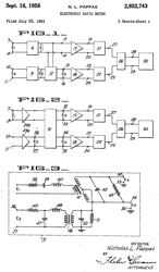
2852743
Electronic ratio meter, Nicholas
L Pappas, HP
Inc, App: 1954-07-23, 324/140D;
324/76.83 - by measuring relative to a reference
signal variations in the signal generator amplitude are
automatically cancelled. This probably was the HP
416 Ratio Meter.
The only patent related to the HP 415 that I could find as
of 2021.
|
---------------- Other old
HP patents ------
3294988 Transducers, Packard
David, HP,
1966-12-27, 374/177; 257/288; 257/467; 310/319; 374/178;
600/488; 600/549; 327/564; 327/509; 601/4; 257/254; 257/417;
257/785; 310/338; 374/E7.035; 374/E7.002 - piezo
pressure or temperature - can be used for medical probe
GR Products
I suspect all of these products are based on either 2173426 or
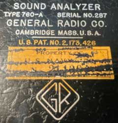
GR 760-A Sound Analyzer is based on the 2173426 1937 patent. (GR
Experimenter Feb 1939: An Analyzer for Noise Measurement,
H.H. Scott. "The new analyzer, however, has a constant percentage
band width at all Frequencies.") (GR
760-B manual)
GR 761-A Vibration Analyzer (GR
Experimenter June 1941: The Vibration Meter - A new
electronic tool for industry, H.H. Scott)
GR 1231-B Amplifier and Null Detector (GR
Experimenter Feb 1948) (1231-B
manual, May 1961)
GR 874-VI Voltage Indicator - for use with 874 slotted lines and
crystal detectors (1959
Catalog P, page 64, GR 11231-B page75)
GR 1232-A Tuned Amplifier and Null Detector (1961
Catalog Q, page 72)
GR 1234 SWR Meter (GR
1968 Catalog T, pdf page 126) (1234
manual, May 1968) Note the HP 415 came out in 1949. HP
introduced the 12 GHz 8410 Vector Network Analyzer
in 1967. (HP
Memory). It worked with the HP 690 series of Backward Wave
Oscillator (BWO) microwave sweep generators. Note that the
parameters used prior to the introduction of S-parameters along
with the HP 8410 were things like "y", "z" and "h" parameters that
required either an open or short at the test frequency.
These tended to cause solid state devices, like microwave
transistors to break into oscillation at some random frequency,
maybe much higher in frequency than the test frequency, thus
making the related measurements near meaningless. Note there
was a similar problem testing Tunnel Diodes until stable test
fixtures were developed.
While looking at the GR offerings related to the microwave
engineering I was doing in the 1965 time frame the GR offerings
seem antiquated when compared to HP.
Military
TM 9-4931-321-34P Direct Support and General Support Maintenance
Repair Parts and Special Tools Lists Standing Wave Ratio Meter,
Hewlett-Packard model Y10-415E (NSN 6625-00-815-6273)
TB 9-4931-321-35 Calibration
Procedure for Standing Wave Ratio meter Hewlett-Packard model 415E
and PRD model 277D
00415-90009 SWR Meter 415E covers serial prefix 0990A- and with
Appendix II Manual changes covers 719-, 545- and 530-. The
Yellow Manual Changes sheets dated 3 February 1986 have changes
for: 1143A, 1709A, 1750A, 2031A, 2433A, 2507A, 2547A and 2509A.
But 2709A is too new for these changes.
Links
Back to Brooke's Products for Sale,
Military Test Equipment, Microwave Test equipment, Military Information, Home page
Page created 28 March 2003.