ESR-micro Meter
© Brooke Clarke 2010 - 2015Protection Circuit
Ranges
Zero Calibration
DIP Socket
DC Power
Battery Internal Resistance
Capacitor Test Results Table
Practical Applications
Thoughts on Replacement Caps
Related
Fly Back Tester
Purchase
Links


Background
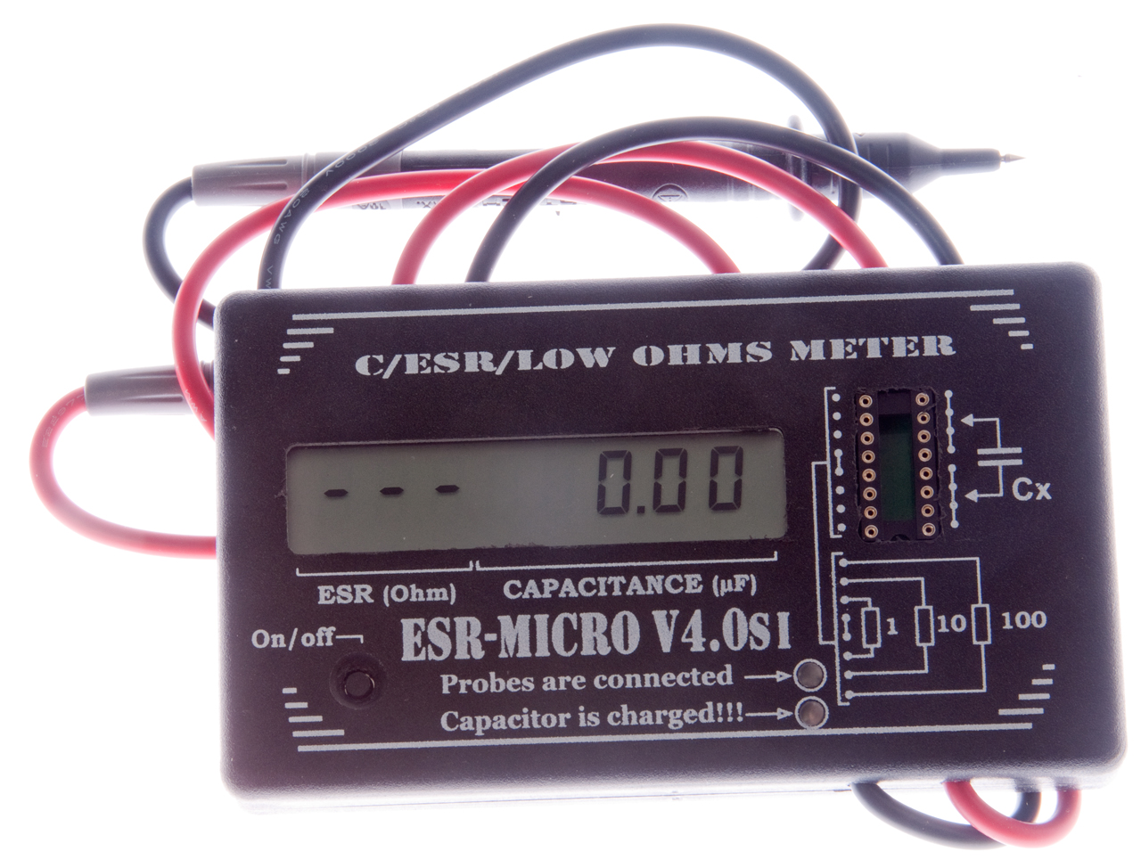
The key thing this meter does that other ESR meters do not do is that this one measures BOTH Capacitance and ESR at the same time. The version 3 ESR-micro had an alternating C then R display, but the version 4 has a two line display. This tester may give better results for some caps than the prior ESR meters. Will be running some tests shortly (Jan 2010). Also there are audio tones that tell you about the resistance of the DUT as well as at power up or down.
More about Capacitor Failure on the Hints & Tips web page.
This ESR meter uses the same method as the Bob Parker unit that is no longer sold by Dick Smith Electronics, but this meter uses a shorter pulse and so does a better job of measuring low value capacitors. For example it measures a 2.2 uF cap to within +/- 0.1 uF.
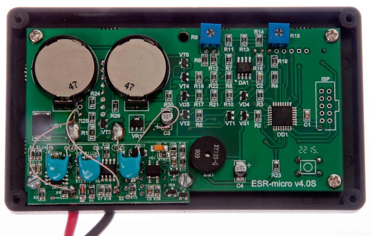
Protection Circuit
The newest model 4.0SI has a protection circuit (I) that's very comprehensive. You can see in the photo 4.0SI Inside (above) that there is a new PCB in the lower left. This circuit detects that the capacitor has some voltage and disconnects the ESR meter and at the same time lights a red LED telling you to remove the probes as soon as possible. In addition there's a green LED that tells you that the probes are in contact with something. This is part of the "I" upgrade.
Testing
With a 220 uF cap and 400 VDC the protection circuit survives, but at 2200 uF at 1500 VDC it fails. One way to characterize this is to look at the energy stored in the capacitor.
Joules = 1/2 * C * V2 So for the above two cases:
Joules = 0.5 * 220E-6 * 400 * 400 = 17.6 Joules
Joules = 0.5 * 2200E-6 * 1500 * 1500 = 2,475 Joules
So 10 Joules should be safe and maybe 1,000 Joules lets the smoke out. Don't know about 100 Joules.
Ranges
Res: 0.00 to 99 Ohm (note: can be used as an Ohmmeter for values below 99 Ohms)
Zero Calibration
Since this meter is capable of measuring very small resistance values it's important that the zero be set to correspond to how the measurement is to be made.
Test Probes
With the meter off place the test probes on the center left DIP socket terminals (a white link is shown between them) and while holding them (like chip sticks) power on the meter and wait a few seconds until the zero calibration is finished.
Socket
If you measure in the socket using a calibration done as described above for test probes the resistance value will be low by a fraction of an Ohm because of the test lead resistance.
So insert a short "U" shaped piece of test lead wire on the right side of the DIP socket so that it forms a short. Power up the meter as before and wait for it to finish the zero calibration.
Warning
If a capacitor is in the DIP socket when the meter is powered up it will do a calibration using the ESR value of that capacitor as the reference resulting in an inaccurate reading afterword.
DIP Socket
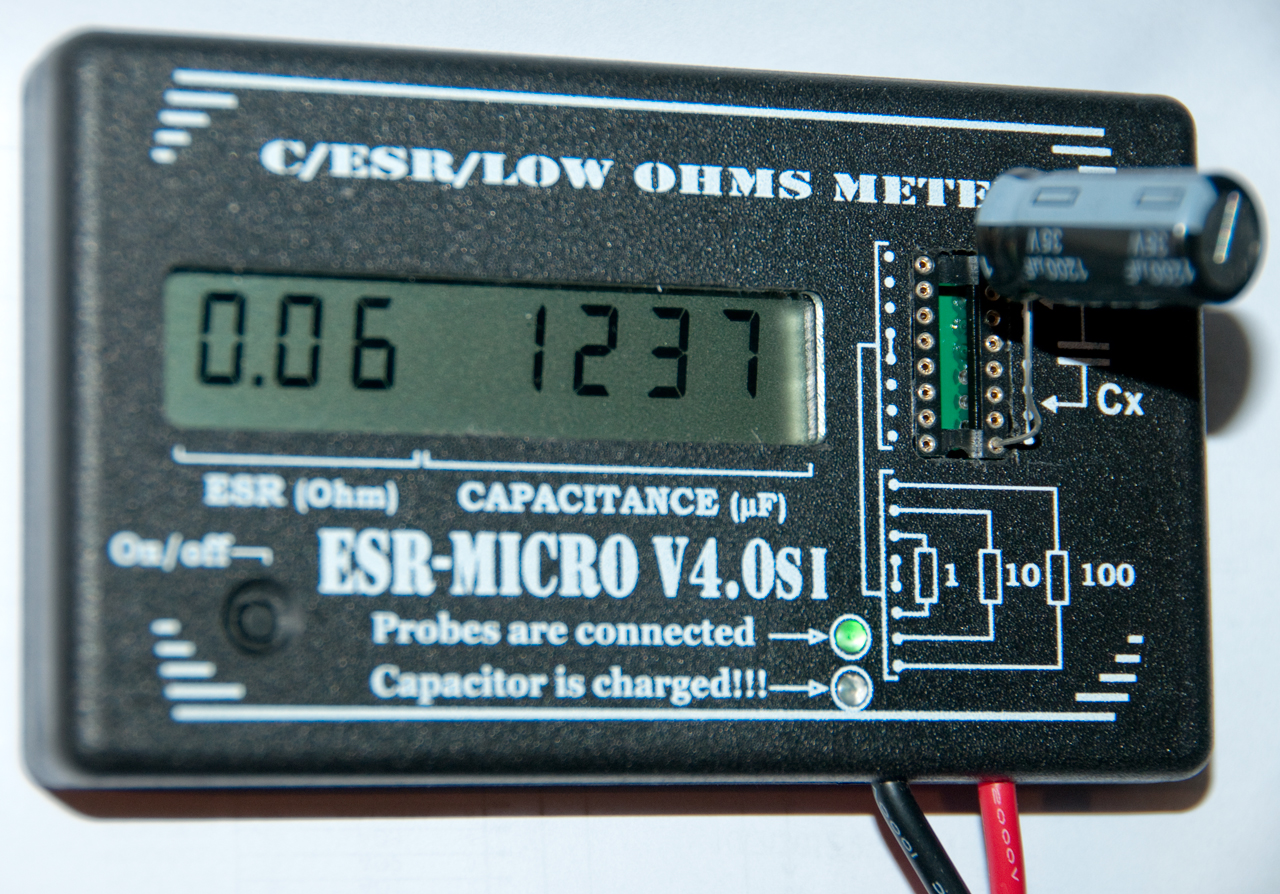 The cap in the photo is
a1200uF 35V.
The cap in the photo is
a1200uF 35V.ESR = 0.06 Ohms
Cap = 1237 uF
- The left center sockets are a short (0 Ohm res). When the meter is powered up with the probes on these sockets a self calibration is done. This is much easier than trying to hold the probes on a penny and pressing a button (that's best done with three hands).
- On the left topmost and bottommost sockets are three
resistors. The center resistor is 1.0 Ohms, then 10
Ohms and finally 100 Ohms to confirm a proper
calibration. For the 0, 1 & 10 Ohm resistors you
hear the beeper that's proportional to resistance.
- On the right are two terminals for testing caps with radial leads and the socket pitch varies from 0.1" to 0.7" in 0.1" steps.
DC Power
To change the batteries remove the four (+) screws on the back. Remove the old batteries using a pointed tool to push back the metal clip. Install new cells + side up. When installing the four (+) screws turn them CCW until you feel the screw drop a thread then turn CW. This avoids cutting new threads in the plastic case.
Battery Internal Resistance V4.0S
When Version 4.0SI is connected to a battery the protection circuit senses the voltage and disconnects the meter so it can not be used on batteries.
Warning: Reverse Polarity will blow the protection diode and maybe some traces, so this is not recommended for the faint of heart.
This means a 10 uF cap is too small, so something like a 470 uF cap will zero the meter. Note the 10 Volt rating of the cap so this setup is good for batteries up to 9 Volts.
Now if the cap is placed in series with the black test lead with it's negative terminal free and it's positive terminal to the black test lead you're ready to test a battery.
Connect the red lead to the battery positive terminal and connect the negate cap lead to the battery negative terminal (to keep the polarity correct for the cap) and wait a couple of seconds for the reading to stabilize. Read the batteries internal resistance.
Using a test lead with alligator clips on each end makes this much easier.
Battery ESR Test Results Table

| No. |
Batt Type |
Chemistry |
OCV |
ZTS # of LED |
4.0S ESR Ohms |
ESR Ohms |
Comment |
| Alkaline |
Fluke 87V | ZTS |
ESR-Cap |
HP
4328A |
|||
| 1 |
1.5V |
Alkaline | 1.098 |
0 |
0.36 |
Dead |
|
| 2 |
1.5V | Alkaline | 1.234 |
0 |
0.30 |
Dead |
|
| 3 |
1.5V | Alkaline | 1.384 |
3 yel |
0.02 |
so so |
|
| 4 |
1.5V | Alkaline | 1.607 |
5 grn |
0.00 |
Fresh |
|
| 5 |
1.5V | Alkaline | 0.1xx |
0 |
----- |
Dead corroded |
|
| 6 |
9V |
Alkaline | 7.06* |
0 |
6.4 |
Dead |
|
| 7 |
9V | Alkaline | 1.467 |
0 |
72** |
Dead |
|
| 8 |
9V | Alkaline | 0.231 |
0 |
11.3 |
Dead |
|
| 9 |
9V | Alkaline | -0.278 |
0 |
12.1 |
Dead |
|
| 10 |
9V | Alkaline | 9.01* |
5 grn |
2.4 |
Fresh |
|
Another way to measure battery internal resistance is to use the HP 4328A milli Ohmmeter. This works for higher voltage batteries.
The best way to measure battery internal resistance is with a meter designed to do that measurement such as the SM8124 (20R) Battery Impedance Meter.
Capacitor Test Results Table
Practical Applications
Heathkit GC-1000 Most Accurate Clock
A used Heathkit GC-1000 Most Accurate Clock is not working properly. The test results when first tested differed from the results a few days later (clock powered up in the mean time). The results seemed difficult to troubleshoot. Testing the electrolytic caps showed most of them to be bad.The following are power supply or decoupling caps where low ESR electrolytics would be good:
C102, C203, C205, C206, C208, C212, C213, C301, C354, C357, C401, C404, C405, C424.
The following are caps where low leakage is important and so either a plastic or low leakage electrolytic would be good:
C348, C353, C355, C359, C412, C414, C421, C422,C425.
Look at the tables on the right side of the page where Red is out of spec and notice that some of the out of spec conditions are for capacitance and some for ESR.
Robert Shaw Controller in GE Oven
My electric oven was running too cold last year ago (see: Recipes: 5 Minute Bread) and a couple of weeks ago my stepson baked a pie where the bottom was raw dough. I had pulled the oven and started shopping for a new one then had sticker shock so decided to see of this one could be repaired. It turneded out that a couple of caps (C1 & C17 in the analog section of the controller board were bad. The repair saved $1,000 to $2,000 for a new oven. See: Hints and Tips: Cold OvenAM-7176A
This came DOA with a DC short at the 24 Volt Input.
After removing the rear finned high power assembly that
included the J3 input connector it was clear using a Fluke
87V DMM that the problem was not in
the finned high power assembly but in the main
chassis. Two large blue caps were tested with the
ESR-Cap meter with these results:
C1= 0.24 Ohms - 1530 uF [s.b. 01132U050AK - 1300uF 50V] so
looks OK
C2= 0.00 Ohms - 1720 uF (Fluke 87V DMM shows
falling resistance not short) ESR meter now reads 0.40 Ohms
- 1720 uF [s.b. 101172U100AJ2A - 1720 uF 100V] so OK
-----
After taking the chassis apart to gain access to the Input
DC Power Supply Filter assembly is was looking like there
may be something wrong with the SCR, but none of the DMM
measurements made sense, so the ESR meter was used.
The following circuit diagram was drawn:
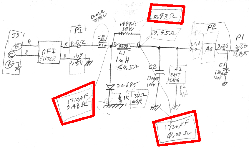 |
At first I thought that the SCR was the
problem (and was thinking that the L1 choke terminal
"1" was the input and "2" was the output, but when I
came back to the drawing noticed the ESR readings that
I've highlighted in red. The L1 coke measures
0.43 Ohms and it's input terminal "2" shows 1710 uF
& 0.48 Ohms to ground. The L1 choke output
terminal "1" shows 0.00 Ohms to ground and 1720
uF. That means the problem is either with the A1
9V battery charging circuit or with C2. But C2
is showing 1720 uF which is exactly the label
value. What's going on???? --- After removing the bracket and unscrewing the negative terminal on C2 (see photo on AM-7176A web page Fig 15) both C2 and the rest of the circuit tested OK. What's going on?? --- When reassembling C2 the answer came. When the screw holding the terminal lug was tightened the terminal rotated to the right causing the many black wires attached to push into the other terminal. While there was not a metal to metal short the insulation on maybe a couple of wires was heavily deformed, not enough to make a hard short, but enough to cause a short when a voltage over maybe 10 Volts was applied. By using the shank of a pocket Phillips screwdriver to reform the black wires they were moved away from the positive terminal and the problem is solved. A minor concern is the 1k resistor that is between the 2N685 SCR gate and cathode (ground) which measures 37 Ohms in either polarity using the DMM and ESR-Cap meter. It looks like the only way the SCR can turn on is if the input voltage goes over 200 so this may be part of the EMP (wiki) protection scheme. This is similar to the crowbar protection circuit used to short the output of a power supply when it's voltage exceeds some threshold, but in this case the gate voltage will never be as high (or higher) than the anode and so will never turn on by the gate. That only leaves the breakdown voltage as a turn on mechanism. There has been some discussion of where to place surge protectors (Wiki) and the answer seems to be as close to the input as possible. In this case it's just after the circuit breaker. |
Thoughts on Replacement Caps
1. Where there is an available replacement (radial, adequate DC working voltage) using Aluminum Organic Polymer caps adds a whole lot of reliability.
It turns out that these are only available in a very limited number of physical and electrical values and are 10 to 100 times more expensive.
A better choice may be either the Low ESR electrolytic or the Low Leakage electrolytic, a plastic or ceramic cap depending on the application.
2 Using low loss electrolytics for things like the NE567 PLL or op amps would be good or plastic.
3. Low ESR electrolytics would be better for power supply decoupling.
Related
HP 4260A Universal Bridge
HP 4274 & HP 4275 LCR Meters
HP 4332 HP 4332 LCR Meter
HP 4395A Combined Network, Spectrum & Impedance Analyzer
Impedance - in general
Megger - Holtzer-Cabot Meg Ohmmeter ZM-14A/PSM-2
TF2700 Marconi TF-2700 Universal Bridge
Zo Transmission Line Impedance (is not constant with frequency)
ZM4 - DC Bridge
ZM-11 - Capacitance-Inductance-Resistance Bridge
EVB ESR Tester
SR715 LCR Meter
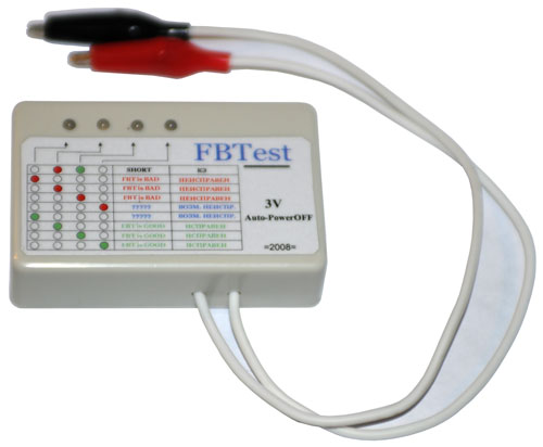
Fly Back Tester
It's based on another of Bob Parker's designs, the LOPT / FBT tester, K7205.pdf)
The Fly Back Tester works by looking for the ringing of an inductor. It's use is not limited to fly back transformers. For example in the second photo below it's connected to a loop antenna and the right hand LED is green (Good).
If interested let me know.
 |
|
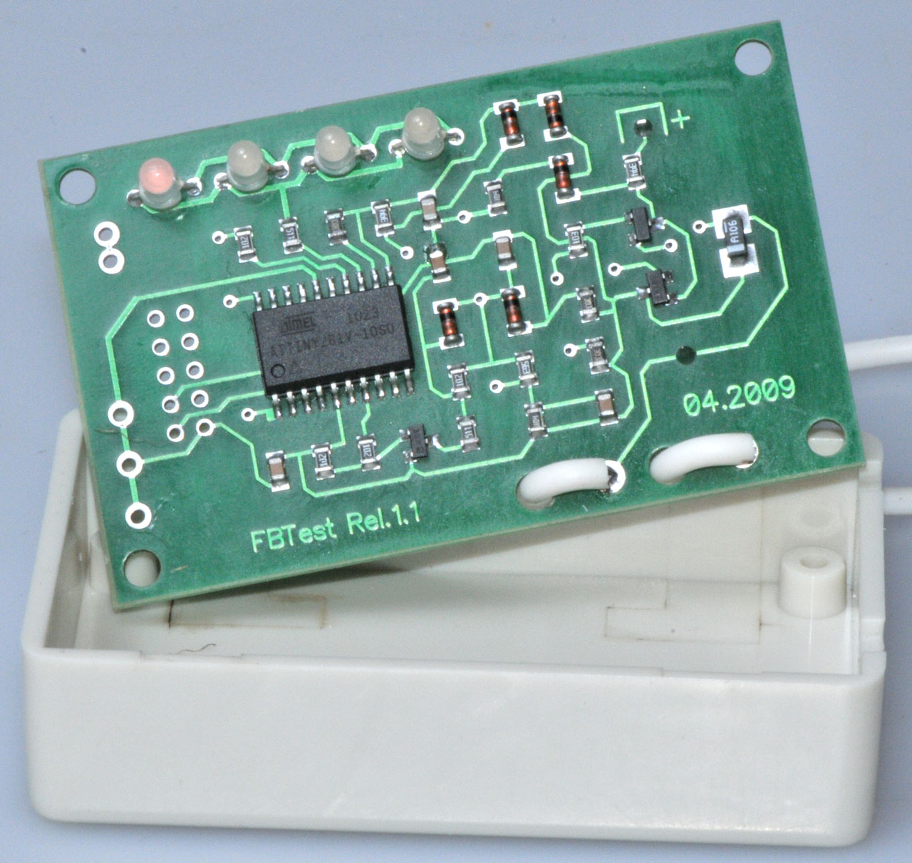 |
on the back side of
the PCB is the CR2032 coin cell and on the front
side (shown at left) is the AT Tiny microcontroller. |
 |
Showing good (right
hand LED is green) when connected to Loop antenna. (high Q at 60 kHz) |
Purchase
Price includes U.S.P.S. mail First Class delivery and Calif. sales tax if you're here.
Links
Back to Brooke's Home, Optics, Wet Batteries, Products for Sale, Military Information web pages.[an error occurred while processing this directive]
Page created 2 Feb 2010.