HP 4328A Milliohmmeter
Brooke Clarke 2008
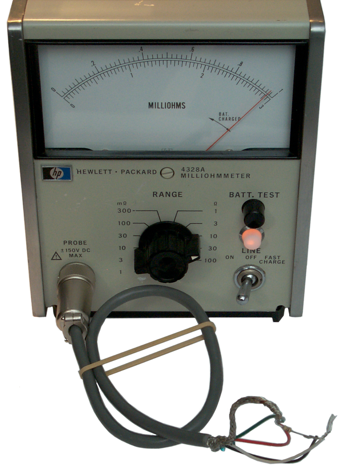
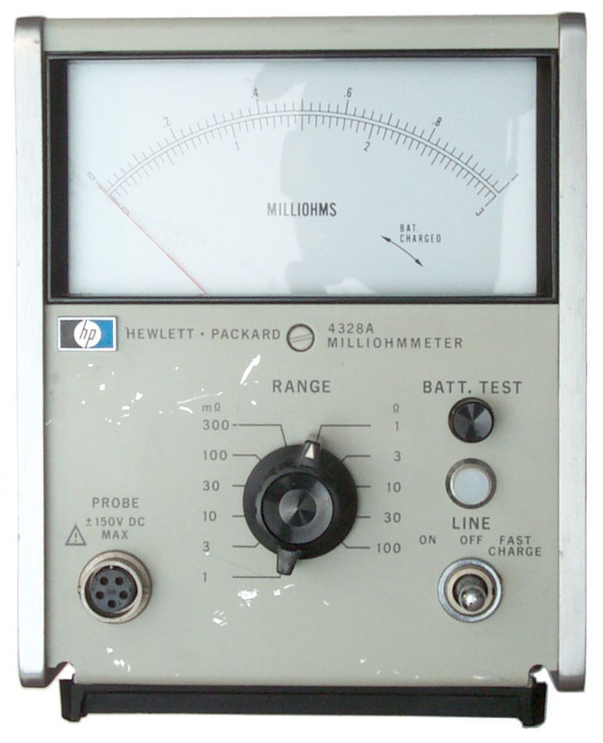 Fig 1
|
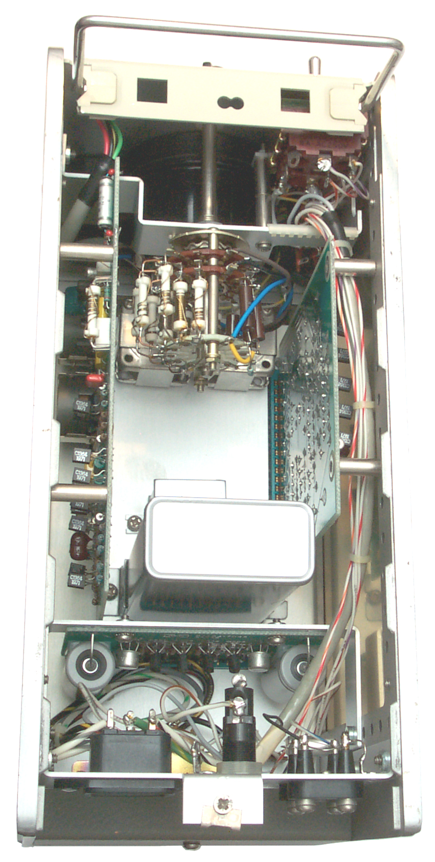 Fig 2 |
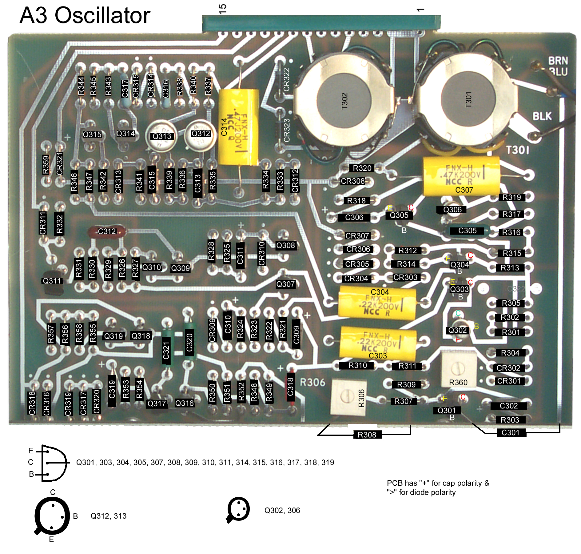 |
Fig 3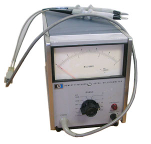 eBay ad, No front Connector, No Battery Charge switch Turn Power sw cw for bat test |
 Fig 4
|
 |
Background
Applications
Test Leads
Versions & Changes
Options
Input Connector
Cleaning
Removing Bottom Cover
Repairs
Links
Applications
Test Leads
Versions & Changes
Options
Input Connector
Cleaning
Removing Bottom Cover
Repairs
Links
Background
While working with the No. 6 Dry Cell and with Power Pole connectors
measurements made with the HP 34401A Multimeter using the
HP 11059A
- Kelvin Test Leads gave erratic
readings for measured values below some tens of
milliohms. The reason being that all the dissimilar
metal junctions were small batteries whose voltage was
temperature dependent. So for measuring below say 50 or
100 milliohms an AC test method is the way to go and that's
what this meter uses.
The test connection uses 5 terminals. Four terminals are the normal Kelvin connections and there's an additional connection for the feedback that maintains the drive at a constant current. The control circuit also causes the meter to peg at full scale when the resistance is too high for the range being measured.
Since the test method is AC based all the test connections in this meter are DC blocked with non polarized (film) capacitors so the input is rated at 150 VDC as safe. This is great since it allows measuring the internal resistance of batteries while they are active or dead or anywhere between. The newer version of this meter, the Agilent 4338B is only specified for 42 Volts. I think this is the number that relates to operator safety rather than instrument capability. So this older meter is far better for testing batteries for tube equipment.
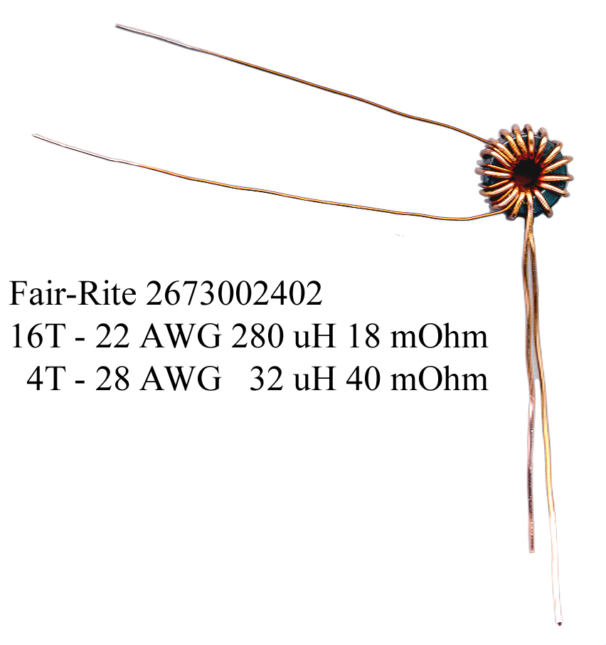
There are limitations to how much inductance can be in series with the resistance to be measured. The meter is specified to measure a resistance in series with an inductive reactance that's three times the resistance.
 This inductor is 280 uH and the 4328A can not measure it's
resistance. Since there's 13" of 22 AWG wire which can
easily be measured when it's not wound on the toroid.
The inductive reactance of 280 uH at 1 kHz is 1.75 Ohms.
The resistance of the wire is about 18 milli Ohms or a ratio
of 97! much too high for the meter to separate.
This inductor is 280 uH and the 4328A can not measure it's
resistance. Since there's 13" of 22 AWG wire which can
easily be measured when it's not wound on the toroid.
The inductive reactance of 280 uH at 1 kHz is 1.75 Ohms.
The resistance of the wire is about 18 milli Ohms or a ratio
of 97! much too high for the meter to separate.
The test connection uses 5 terminals. Four terminals are the normal Kelvin connections and there's an additional connection for the feedback that maintains the drive at a constant current. The control circuit also causes the meter to peg at full scale when the resistance is too high for the range being measured.
Since the test method is AC based all the test connections in this meter are DC blocked with non polarized (film) capacitors so the input is rated at 150 VDC as safe. This is great since it allows measuring the internal resistance of batteries while they are active or dead or anywhere between. The newer version of this meter, the Agilent 4338B is only specified for 42 Volts. I think this is the number that relates to operator safety rather than instrument capability. So this older meter is far better for testing batteries for tube equipment.
There are limitations to how much inductance can be in series with the resistance to be measured. The meter is specified to measure a resistance in series with an inductive reactance that's three times the resistance.
 This inductor is 280 uH and the 4328A can not measure it's
resistance. Since there's 13" of 22 AWG wire which can
easily be measured when it's not wound on the toroid.
The inductive reactance of 280 uH at 1 kHz is 1.75 Ohms.
The resistance of the wire is about 18 milli Ohms or a ratio
of 97! much too high for the meter to separate.
This inductor is 280 uH and the 4328A can not measure it's
resistance. Since there's 13" of 22 AWG wire which can
easily be measured when it's not wound on the toroid.
The inductive reactance of 280 uH at 1 kHz is 1.75 Ohms.
The resistance of the wire is about 18 milli Ohms or a ratio
of 97! much too high for the meter to separate.Applications
Battery
Internal Resistance - The 4328A is specified to have up to 150
VDC across the test terminals. One of the key
applications is to measure battery internal resistance.
The newer HP/Agilent 4338B is specified for 42 VDC max which comes about because of human safety regulations.
Capacitor Effective Series Resistance (ESR)
Switch, Relay. Connector contact resistance
The newer HP/Agilent 4338B is specified for 42 VDC max which comes about because of human safety regulations.
Capacitor Effective Series Resistance (ESR)
Switch, Relay. Connector contact resistance
Test Leads
When making a Kelvin DC resistance measurement the lead lengths do not matter. But when making an AC resistance measurement the inductance of the leads becomes important.
XL = 2 * PI * F * L so for a 1 milli ohm inductive reactance at 1 kHz you would have an inductance of 159 nH. A rule of thumb is 1 nH per mm of length for a wire so 159 mm is 6.25". But the 4328 includes a phase sensitive detector so is supposed to only measure the real part but my guess is it can not do it if the magnitude of the inductive reactance is three times larger than the resistance. Note that the 1 milli ohm and the 90 ohm R - L networks shown in Fig 5-1 and 5-2 have the inductive reactance twice the value of the resistance. The test leads that I've seen for sale on eBay look like they are 3 feet long, which is too much for the 1 milli Ohm range. Another possible reason for the lead length limits by range is the error caused by the difference in length of the test leads prior to joining the Kelvin connections.
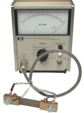
Photo at left is showing the resistance of a 50 Amp shunt that produces 50 mv full scale, i.e. it's a 1 milli Ohm 4 terminal resistor.
The A current and B current leads are connected to the high current lugs and the A voltage and B voltage terminals are connected to the small screws.
Above I said the proof was in the pudding, well this pudding tastes very good. The meter has not been adjusted or tweaked in any way, it just turned on indicating 1.00 milli ohms. When switching to the 3 milli Ohm range the needle drops back to 1/3 scale right on 1.00 milli ohms. Sweet.
Note this is a measurement that the HP 34401 can NOT make because it's a DC Ohms instrument.
Now to decide which Kelvin clips to get.
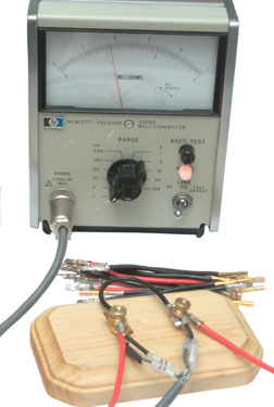 HP 4328A Milliohmmeter Kelvin Test Base
27 April 2008 - This is a wood base made using a couple of
plastic 6-32x1" screws and some brass hardware. A lot
lower in cost, and more importantly available within a hour or
so of thinking about it.
I have made up some wires for the 5590BA ver 2 Battery Adapter that have the socket pin on one end and a Power Pole 45 Amp terminal on the other end. The wire is 14 AWG super flex. Both ends have been joined by crimping. Before pressing the pins into the socket (very difficult to get them out) I'd like to test them.
I tried to just put the metal terminals under the thumb nut, but the plastic screw bends when it's tightened and that squirts out the round socket pin. By putting a second (dummy) lead on the other side of the post the forces are balanced and you can easily clamp both leads. Since the dummy lead is not connected to anything it does not effect the measurement.
The lead shown is reading about 1.1 Milli Ohm (just off scale on the lowest range. Note this includes some resistance for the socket pin and Power Pole terminal, the two crimp joints and about 4 inches of 14 AWG wire.
The test leads are the same ones shown above connected to the 50 Amp shunt.
The wooden base is from Michael's (about 60¢) and the plastic screws from Friedman Brothers (about 60¢) plus a few dollars of gas (about $4.00 per gallon).
Mueller 75K Kelvin Clips
 Each Jaw is a separate contact to the two
clips shown represent a four terminal (Kelvin) connection.
Each Jaw is a separate contact to the two
clips shown represent a four terminal (Kelvin) connection.If you clip onto the edge of 10 mil brass shim stock as one clip is slid along the edge the resistance changes in a very smooth manner. Three inches of Phosphor Bronze 10 mills thick and about 400 mills wide is about 3 milli Ohms.
The metal may be silver with gold plating. The problem with the leads as shown is that the max distance between the two test points is limited to a few inches. This is a good thing for good accuracy the Amp Turns for the loop formed by the test leads is minimized, but it's not too convenient for some measurements. Another set of leads with more reach would be better. Fir example the HP 1159A Kelvin Test Leads can reach a little more than one foot.
Measuring Wire
The Kelvin Test Base makes it easy to measure wire resistance. Most wire tables show resistance in Ohms per 1,000 feet, this is the identical number as Milli Ohms per foot. These values range from about 1 Milli Ohm for 10 AWG to 1014 Milli Ohm for 40 AWG all in range on the 4328A for a one foot length.Versions & Changes
In Fig 3
above is an HP 4328A, the same model number as my s/n
1828J07728 Milliohmmeter. But it has a number of
differences.
There is no separate BATT. TEST push button, but that might be done by turning the power push button clockwise (hard to see in photo).
Manual Changes Table
The manual is good for the latest version and needs to be back
dated for older instruments.
There is no separate BATT. TEST push button, but that might be done by turning the power push button clockwise (hard to see in photo).
Change 10 switched to the
separate Battery Test button which also involved changing
the external sheet metal parts (maybe a color change) and
changing the type of power cord to the IEC standard
cord. Also the power switch was changed to a three
position toggle type
The probe seems to be fixed to the instrument and in this
particular eBay auction one of the probes is broken.Change 11 adds a connector to
the probe cable.
Manual Changes Table
The manual is good for the latest version and needs to be back
dated for older instruments.| Yr |
# |
1 |
2 |
3 |
4 |
5 |
6 |
7 |
8 |
9 |
10 |
11 |
12 |
13 |
14 |
15 |
16 |
17 |
18 |
19 |
20 |
|
| 1967 | 723/724-00050 to -00120 |
71 |
Y |
Y |
Y |
Y |
Y |
Y |
Y |
Y |
Y |
Y |
Y |
Y |
Y |
Y |
Y |
Y |
Y |
Y |
Y |
Y |
| 1967 | 723/724-00121 to -00210 |
90 |
Y |
Y |
Y |
Y |
Y |
Y |
Y |
Y |
Y |
Y |
Y |
Y |
Y |
Y |
Y |
Y |
Y |
Y |
Y |
|
| 1967 |
747/748-00211 to -00270 |
60 |
Y |
Y |
Y |
Y |
Y |
Y |
Y |
Y |
Y |
Y |
Y |
Y |
Y |
Y |
Y |
Y |
Y |
Y |
||
| 1968 | 810/811-00271 to -00300 |
30 |
Y |
Y |
Y |
Y |
Y |
Y |
Y |
Y |
Y |
Y |
Y |
Y |
Y |
Y |
Y |
Y |
||||
| 1968 | 813/814-00301 to -00341 |
41 |
Y |
Y |
Y |
Y |
Y |
Y |
Y |
Y |
Y |
Y |
Y |
Y |
Y |
Y |
Y |
|||||
| 1968 | 818/819-00342 to -00440 |
98 |
Y |
Y |
Y |
Y |
Y |
Y |
Y |
Y |
Y |
Y |
Y |
Y |
Y |
|||||||
| 1968 |
818/819-00441 to -00730 |
289 |
Y |
Y |
Y |
Y |
Y |
Y |
Y |
Y |
Y |
Y |
Y |
Y |
||||||||
| 1970 |
1030/1040 and below |
? |
Y |
Y |
Y |
Y |
Y |
Y |
Y |
Y |
Y |
Y |
Y |
|||||||||
| 1972 | 1210 and below |
? |
Y |
Y |
Y |
Y |
Y |
Y |
Y |
Y |
Y |
Y |
||||||||||
| 1972 | 1233 and below |
? |
Y |
Y |
Y |
Y |
Y |
Y |
Y |
Y |
Y |
|||||||||||
| 1973 |
1334-02811 and below |
? |
Y |
Y |
Y |
Y |
Y |
Y |
Y |
Y |
||||||||||||
| 1974 |
1420 and below |
? |
Y |
Y |
Y |
Y |
Y |
Y |
Y |
|||||||||||||
| 1975 | 1542J04620 and below |
? |
Y |
Y |
Y |
Y |
Y |
Y |
||||||||||||||
| 1975 | 1542J04870 and below |
? |
Y |
Y |
Y |
Y |
Y |
|||||||||||||||
| 1975 |
1542J05050 and below |
? |
Y |
Y |
Y |
Y |
||||||||||||||||
| 1978 | 1828J05530 and below |
? |
Y |
Y |
Y |
|||||||||||||||||
| 1978 | 1828J06420 and below |
? |
Y |
|||||||||||||||||||
| 1978 |
1828J05711 and above |
? |
||||||||||||||||||||
| 1989 Errata all manuals: C1 |
||||||||||||||||||||||
| 1978 | 1828J07291 and above: C2 this meter is 1828J07728 |
|||||||||||||||||||||
| 1978 | 1828J07961 and above: C3 |
|||||||||||||||||||||
| 1978 | 1828J09594 and above: C4 |
|||||||||||||||||||||
Options
AC only Power Supply
The stock PCB has two voltage regulator circuits (+13 and -13 VDC) where each regulator circuit uses three transistors (six total)001 Internal Battery
The only difference is that the plug-in power supply PCB changes. The option 001 PCB has no active voltage regulation, but just a 15.4 Volt zener diode that feeds the Ni-Cad batteries that are attached to the board through a Silicon diode (0.6 V drop) so open circuit voltage is 14.8 VDC. Ni-Cad cells are rated 1.2 Volts when out of charge and around 1.4 volts at full charge so a 10 cell pack would provide between 12.0 and 14.0 volts. The two batteries that make up each pack must be small.The AC power consumption is specified at 2 watts and option 001 is good for 15 hours. The batteries, two in each supply (four total) are each 6 Volt 225 mAH. So for 15 hours operation the current must be less than 15 ma.
Note that when option -001 is used the Milliohmmeter will only work when the batteries are charged since they are directly connected across the supply rails. If discharged or bad the meter will not function properly.
For battery only operation the line cord must be unplugged. The modes of operation are: OFF, Fast Charge (charging but no meter operation), ON charge and meter operation.
Input Connector
The Probe connector is the Hirose RM12BRD-5S and the
mating connector is the RM12BPE-5PH or the new number for the
lead free version. I have a few on order from Digikey.
16 Apr 2008 - Digikey shipped the connectors yesterday (the day they were ordered). Should be here 22 April 2008
22 Apr 2008 - HR1732-ND is the new lead free connector. The solder cups have an I.D. of 0.040" (measured with gauge pins). That corresponds to 18 AWG wire but that wire has too much resistance.
When making a cable there are limitations:
1. for resistance ranges 3 milli Ohms to 100 Ohms there is some maximum resistance and lead length allowed. The max resistance is determined by the compliance of the Kelvin correction circuitry. The max length is determined by the accuracy spec and the reactance the lead presents that needs to be removed by the phase detector.
2. for the 1 milli Ohm range the leads must have more than 2 milli Ohms resistance and less than 20 milli Ohms resistance AND the total length must be less than 40 cm (15 3/4"). I think the minimum resistance is related to the current control circuit (pin 2) when the test current is 150 ma.
So to make a cable suitable to use on the 1 milli Ohm range there are limitations on the wire size.
I've heard that meters with different batch (serial) numbers may have different connector wiring. YMMV.
15 Jan 2014 - It may be that instead of connecting pin 3 and pin 5 to get the oscillator to work maybe connecting pins 2 and 3 should have been connected.
That may be in general or may be a serial number specific difference?
I've run the brown and green wires inside the shield braid so you only see the braid in the photos. One source of error is the Amp Turn product for the area enclosed by the test leads. If the area changes that can cause an error. Some experimentation may be needed to see if using two separate test leads from the connector will work OK.
16 Apr 2008 - Digikey shipped the connectors yesterday (the day they were ordered). Should be here 22 April 2008
22 Apr 2008 - HR1732-ND is the new lead free connector. The solder cups have an I.D. of 0.040" (measured with gauge pins). That corresponds to 18 AWG wire but that wire has too much resistance.
| Pin |
Internal Color |
Clips May 2014 |
Function |
Connection |
Belden 9610 |
| 1 |
Yel |
Clip 1 V |
Voltage @ Cur Source |
Clip
B voltage |
Wht |
| 2 |
Grn |
Clip 1 I |
Control
of Current Source |
Clip
A Current |
Grn |
| 3 |
Blk |
Shield |
Current Source |
Clip
B Current sen |
Blk |
| 4 |
Red |
Clip 2 V |
Voltage @ Cur Sink |
Clip
A Voltage |
Red |
| 5 |
wht/blk |
Clip 2 I |
Current Sink - Shield |
Clip
A Current Shield |
Brn Shld |
1. for resistance ranges 3 milli Ohms to 100 Ohms there is some maximum resistance and lead length allowed. The max resistance is determined by the compliance of the Kelvin correction circuitry. The max length is determined by the accuracy spec and the reactance the lead presents that needs to be removed by the phase detector.
2. for the 1 milli Ohm range the leads must have more than 2 milli Ohms resistance and less than 20 milli Ohms resistance AND the total length must be less than 40 cm (15 3/4"). I think the minimum resistance is related to the current control circuit (pin 2) when the test current is 150 ma.
So to make a cable suitable to use on the 1 milli Ohm range there are limitations on the wire size.
I've heard that meters with different batch (serial) numbers may have different connector wiring. YMMV.
15 Jan 2014 - It may be that instead of connecting pin 3 and pin 5 to get the oscillator to work maybe connecting pins 2 and 3 should have been connected.
That may be in general or may be a serial number specific difference?
Cable Wiring
See table above. The A Kelvin clip has Current Sink from pin 5 (as both the Brown wire and at the Kelvin clip the shield around the cable) and connected to the same clip terminal Control of Current Source pin 2 (green cable wire). The cable shield is not connected at the Hirose connector. So there's three connections at this clip terminal.I've run the brown and green wires inside the shield braid so you only see the braid in the photos. One source of error is the Amp Turn product for the area enclosed by the test leads. If the area changes that can cause an error. Some experimentation may be needed to see if using two separate test leads from the connector will work OK.
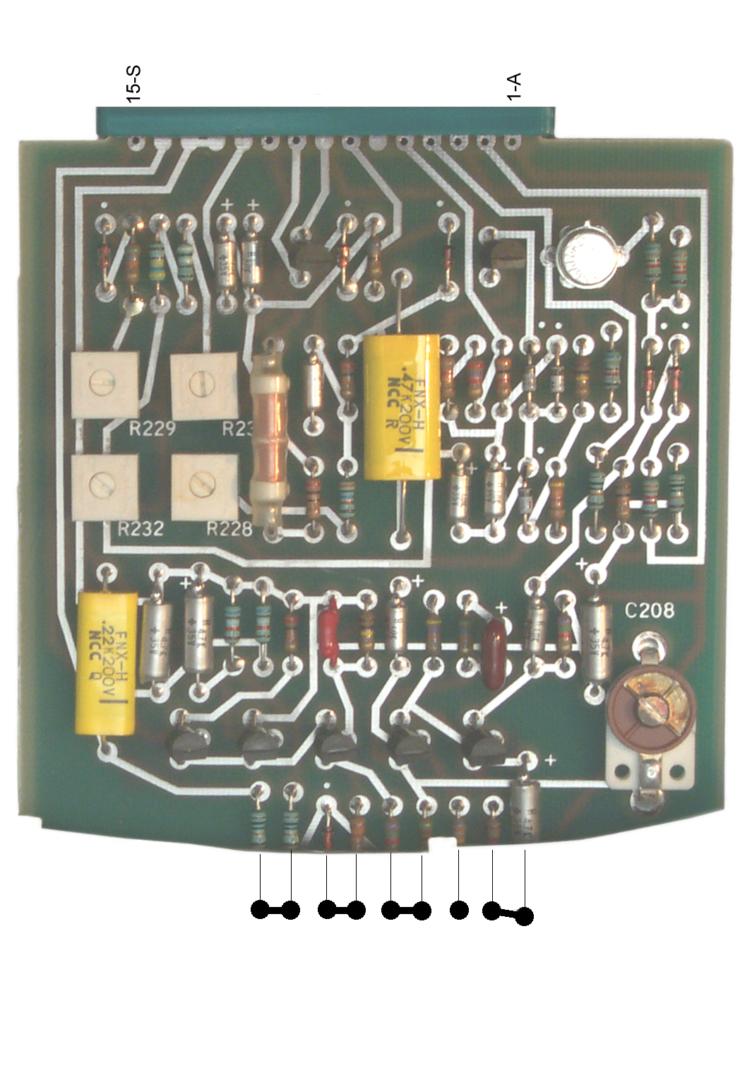
Cards & Card Sockets
Fig 4 above shows the motherboard which has a socket at the top for the A3 Oscillator card and another socket at the bottom for the A2 amplifier phase detector card. These are both two row sockets going from 1 to 15 on one side and A to S (A, B, C, D, E, F, H, J, K, L, M, N, P, R, S) on the other side. The S3 connector has all the pins paired, i.e. 1 to A, 2 to B, etc. but the A2 card only has some pairs jumpered. The power supply socket that's chassis mounted is a single row A to S socket.Cleaning
There were stickers all over
this instrument, but with a shop rag and some Oops! they are
all gone as well as the residue.
Removing Bottom Cover
The bottom cover can be removed
while the feet are installed.
Using a PosiDrive 2 bit remove the screw and slide the cover back.
Swing the tilt stand bail out to clear the foot and slide cover off.
Using a PosiDrive 2 bit remove the screw and slide the cover back.
Swing the tilt stand bail out to clear the foot and slide cover off.
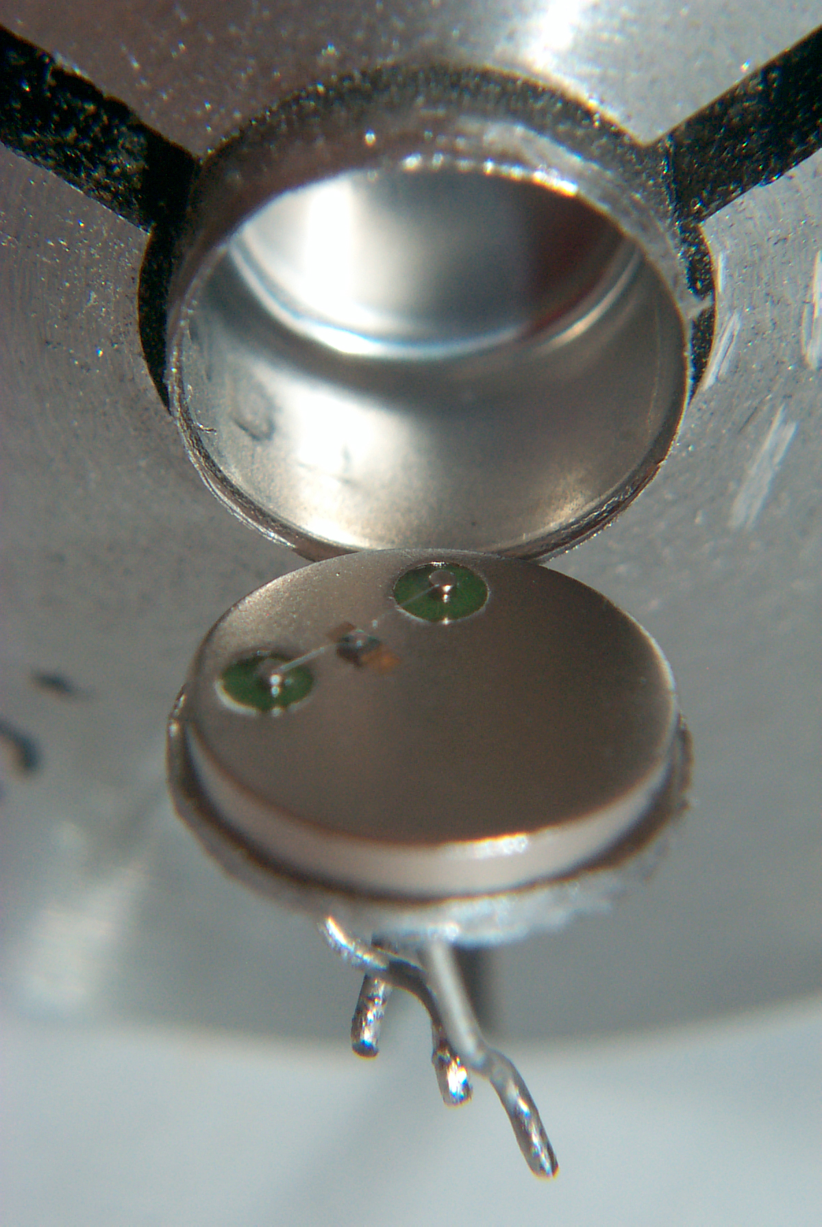
Repairs
After making up a Probe cable the meter did not deflect on any range.1) The first problem was an open transistor in the power supply, Q302 a 2N1711. It was replaced by another TO-5 packaged NPN, a 2N3053 and now the power supply is working.
 |
 |
 |
 |
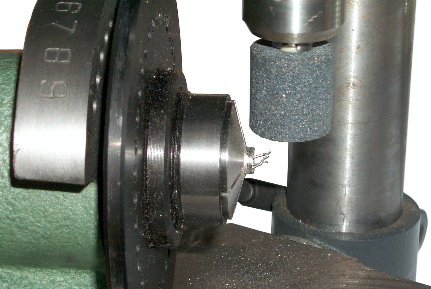
| Spin Index & Drill
Press used to de-lid TO-5 transistor Q302 |
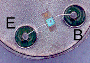
Q302
in 5C collet with base folded out |
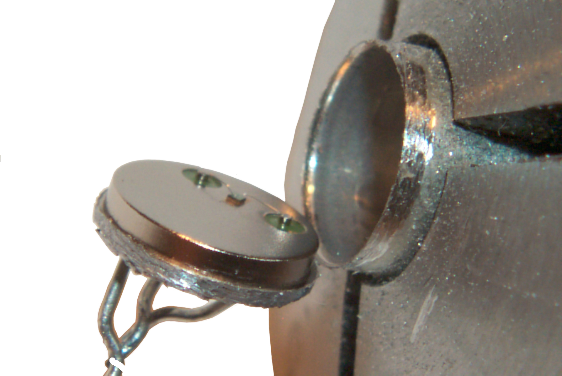
another
view of Q302 Kodak DC290 image. |
The
emitter wire is NOT attached to the chip You can see the eutictic die attach scrub marks. HP 6200 Scanner image at 1200 DPI |
2) The second problem is there's no oscillation signal so something in the Q301 to Q304 range is not right.
In order to have an oscillation
the probe current source (pin 3) needs to be connected to the
current sink (pin 5). The other pins can be left open
and you will still see a little more than a volt rms at Q303
emitter with a frequency near 1 kHz for every switch position.