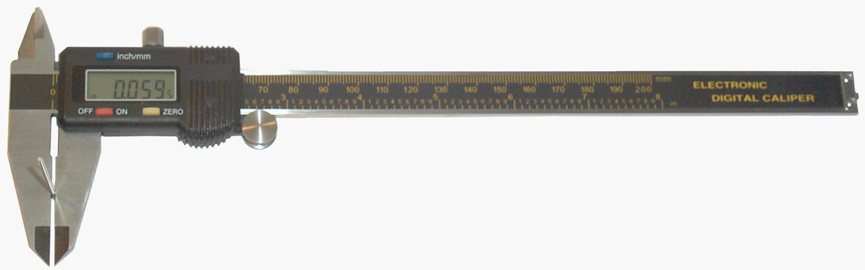
Vernier Caliper
 If you're going to
have only one precision measuring tool Vernier calipers are the
best choice. I started out with an analog version and a few
years ago upgraded to this digital version. The analog
caliper had a max capability of 6 inches and at times that was not
enough, so the digital ones are 8 inch. So far I like this
range for the types of things I do. I have these within arms
reach of where I'm sitting now. The thing that makes
these so versatile is the three measurement modes:
If you're going to
have only one precision measuring tool Vernier calipers are the
best choice. I started out with an analog version and a few
years ago upgraded to this digital version. The analog
caliper had a max capability of 6 inches and at times that was not
enough, so the digital ones are 8 inch. So far I like this
range for the types of things I do. I have these within arms
reach of where I'm sitting now. The thing that makes
these so versatile is the three measurement modes:- Making an outside measurement using the jaws as shown above where a 60 mil minimum gauge pin is being measured
- Making an inside measurement using the points opposite the jaws
- Making a depth measurement using the rod on the right.
- Making a step measurement using the offset at the left.
(see Ref 1)
The 123 Block is a handy accessory to the calipers.
WARNING
If the rod is too big to fit into a hole you can use a metal pin and measure with the jaws, this time setting zero at the bottom of the hole and reading with the pin out of the hole.
Harbor Freight 47260 made in China. The made in Japan calipers are better in that when you turn them off the battery lasts longer. The made in China calipers only turn off the LCD so the battery does not last long. You can take the 357/303 battery (+ up) out when you're not using them, but it's a PITA.
There are some weak points:
- When measuring thin items like a sheet of paper, the thickness of a hair from your head, the thickness of a clock suspension spring the half mil resolution is too coarse a measurement. A micrometer (see below) is better for this type of measurement.
- When measuring the inside diameter of a small hole the flats
on the inside measuring jaws do not allow them to seat on the
diameter but instead cause the reading to be a little
smaller. You could work up an equation based on the
known flat dimensions that would correct for this, but it
still would be questionable. A better way is to use plug
gauges (see below) to see which goes into the hole and which
is a no go.
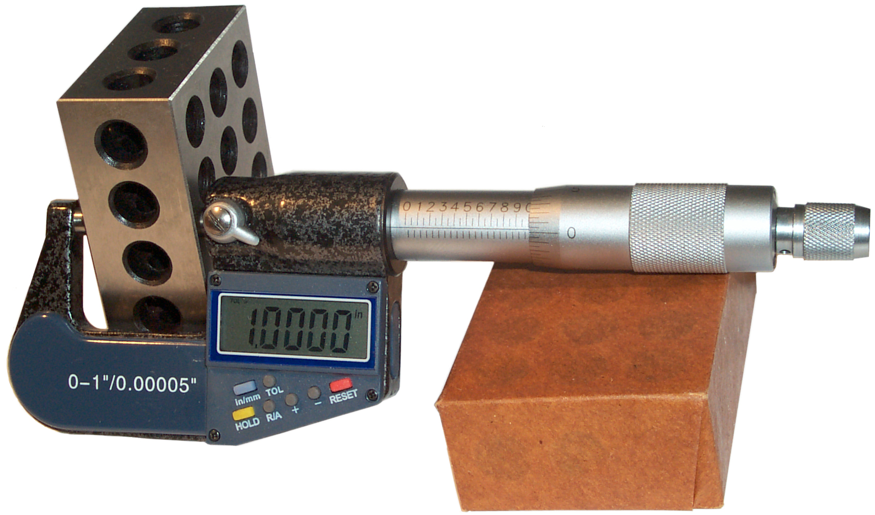
Micrometer
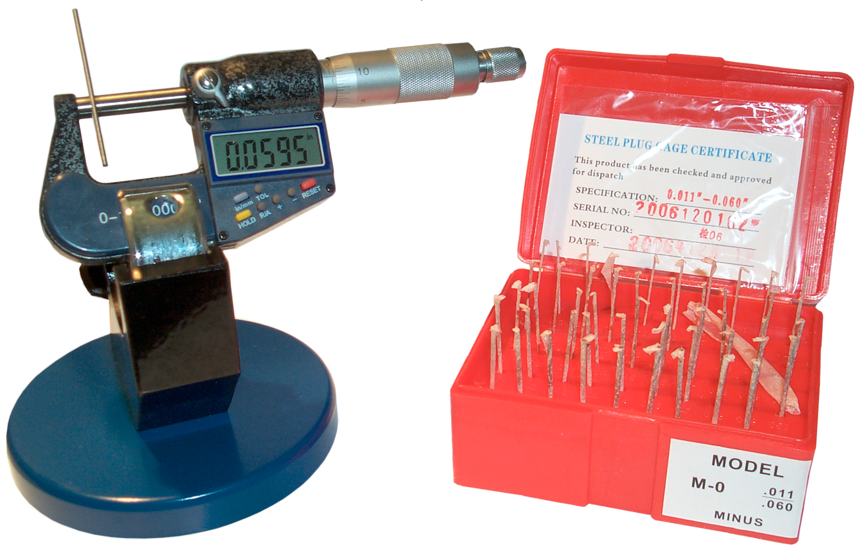 |
This mike reads to 0.000,05" i.e. 50
millionth's of an inch. Most 0-1" mikes only read to
0.001 or a thousandth of an inch, but then there's not
much point in getting one if your calipers can make the
same measurement. In the photo at left the mike is showing 0.05950" where the right most digit is either 0 or 5. The problem with calipers is than when measuring things that are thin you can't get much accuracy. Also in the photo above is a set of 50 gauge pins from 0.011 to 0.060" in 0.001" steps all on the minus side of nominal. Hopefully they will fill another weakness of the Vernier Calipers and that's measuring the inside diameter of small holes. The problem with the calipers is that the flat on the tips are a little under 0.020" so when measuring a small hole they report the I.D. a little smaller than it really is. Using pins should me much more accurate for small holes. The third item in the photo is a mike stand. I got three different models to see which one I liked the best. The one shown is the heaviest at 3 lb 20 oz and has about as small a foot print of any of the others. For measuring small items that can be brought to the mike the stand sure is great. Of course the mike can easily be removed to measure things not easily brought to the stand. Let me know about the cable needed for remote readout. 9 March 2008- replaced the LR44 battery in the mike. Also known as AG13. 1.55 Volts 11.5 mm diameter 5.65mm hi. Positive toward cap. |
 |
M-1 .061 to .250 Plus This pin gauge set is a continuation of the smaller set. The box is 11" x 7½" x 2½" compared to the 4" x 3" x 2" for the smaller set. The mike is holding a pin reading 0.08010 which is inserted into the solder cup of a 5590BA Battery Adapter socket. This is the diameter that determines what wire size will fit. Without this pin gauge set it could not be measured accurately. I tried using two pins from the smaller set and the answer was an ID that was too small. Uses: * measure the ID of a solder cut * measure the ID of shrink tube * measure the hole where the high current output screw fits on the EL1132 Electronic Load. Note the Screw Chek'R will not accept the screw in 10-32 but it's very loose in 12-32. The OD says it's a #10. The mating hole accepts a pin that's the size of a 10-32 tap drill. So the screw is a 10-32 but a little on the big side. The mike has blue plastic plates on both sides where your thumb and finger are going to hold it. That's to keep body heat from expanding the metal. So another advantage of the stand is you are not heating the mike at all. |
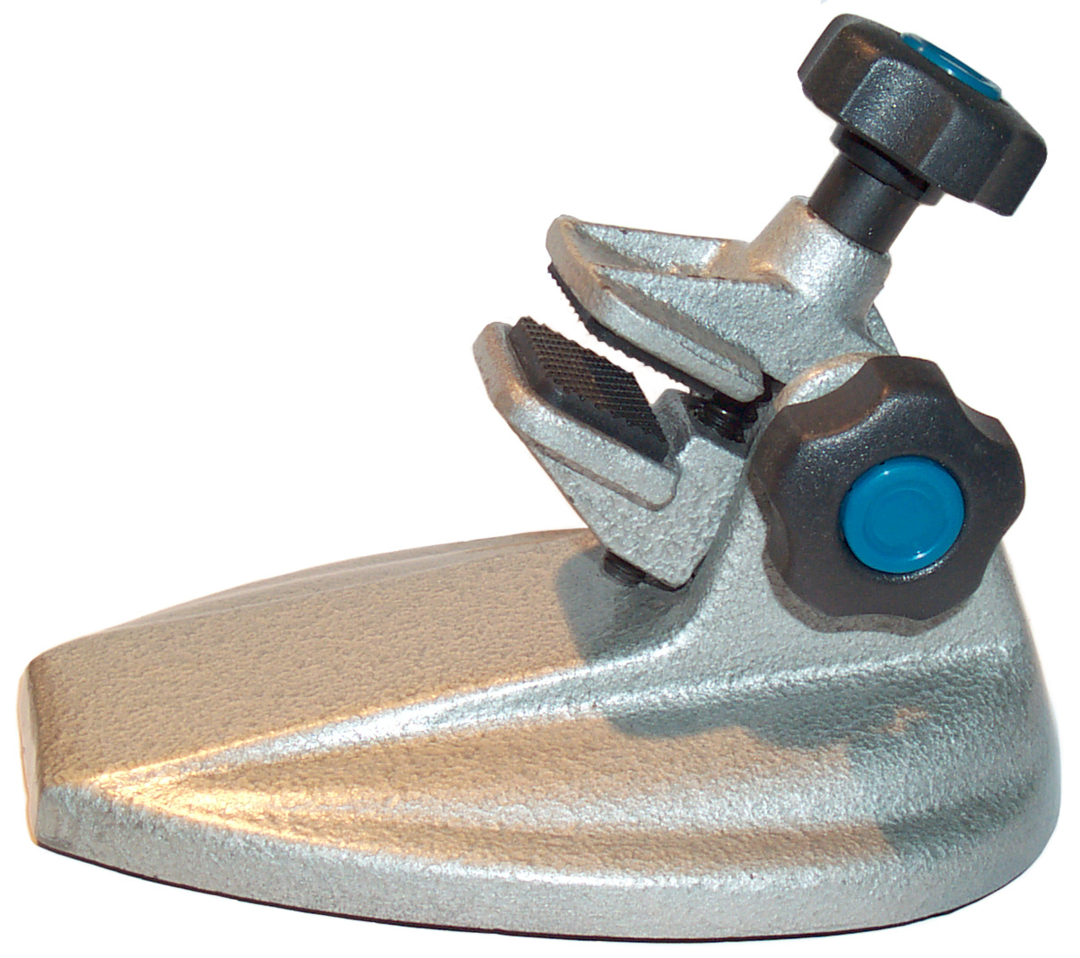 |
There's probably some application where this stand might work better than the one above. This would be my second choice. All these stands to not hold the mike in a rigid manner, but instead allow it to tip about an axis. This one weights 2 lb 5 oz and is a little larger. |
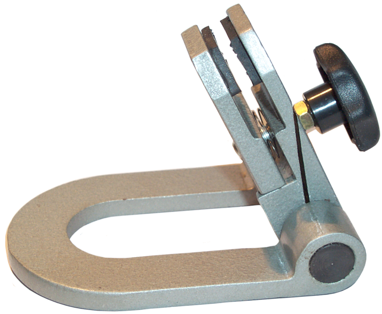 |
This stand would be handy for fitting into a tool chest or where small size is important. It folds flat when not in use. When the knob is tightened it not only clamps the mike but also snugs the rotation about the axle. Has a couple of coil springs to open the jaws. |
123 Block (aka 1-2-3 Block)
These are hardened steel blocks with outside dimensions of
exactly 1 by 2 by 3 inches. These came as a set of
two. There are also 246 blocks that are twice as
big. The mike is reading 1.00000".
On the 2x3" face there are 5 tapped holes , the center and from
center the 4 diagonals, like 5 on a pair of dice. The
other 10 holes are 0.36" through.
 |
The five tapped holes are 3/8-16 and in
most the threads are continuous all the way through.
There are some web pages that mention a problem with the
threads in these holes, but mine are fine. It's not
clear to me how you can use the tapped holes to join two
blocks. Note the major diameter of a 3/8-16 bolt is
about 0.37" and so will not go through a 0.36" dia
hole. The thing to have would be some pieces of
round stock about 1/2" long and a little under 0.36"
diameter with a hole drilled and tapped at the center of
the length at 90 decreed to the center line for ¼-20
thread. This would allow using ¼-20 bolts and
washers to make a 90 degree combined 123 fixture that was
square. Note on the left side of the micrometer frame just below the mike barbell there is a blue plastic cap. When the cap is removed there are 4 contacts on a printed circuit board for some external readout. If you know what cable and connector work here let me know. |
 |
When trying to figure out a way to measure the flywheel from a Toy Engine using a pair of 123 blocks sure made it easy. The digital calipers are making a deepth measurement from the top of the boss to the back plane of the flywheel. Other measurements can be made to the plane of the 3 bumps in a similar fashion. I can see you really do want two blocks. |
Dial Indicator
There are a number of uses for the dial gauge. Mine is a Harbor Freight 623 sale item with the 5646 Magnetic Base. There are also much better analog and digital versions.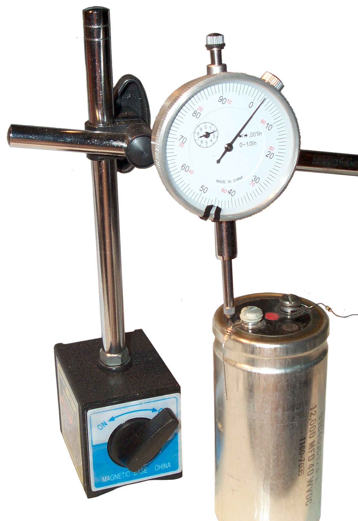 |
The dial gauge is used to make relative
measurements. The plunger is spring loaded so the
stand needs to be setup so that the plunger is below all
the heights that are going to be measured when it's
bottomed. By lifting the plunger from the top,
moving the part underneath and lowering the plunger down
on the part, one height can be compared to
another. The stand shown is a magnetic type with a
switch to lock it down or allow it to be moved.
This would be handy on a machine tool. There are
also stands that are just heavy for use on granite flat
surfaces. |
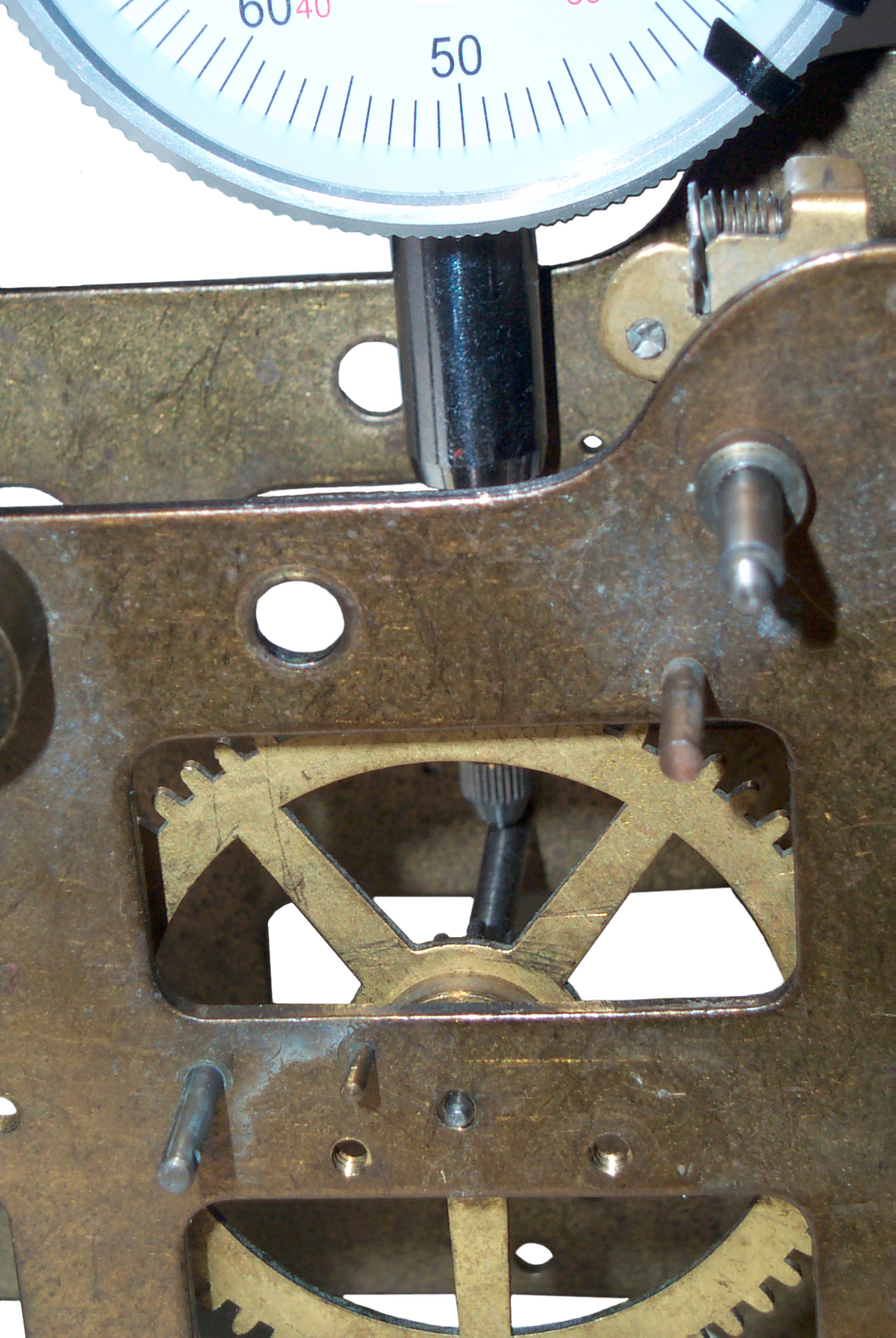 |
For example to see how much slop there is between a clock pivot shaft and it's bearing. In this case there's no need to zero the dial, just watch how much it moves as up or down force is applied to the shaft. |
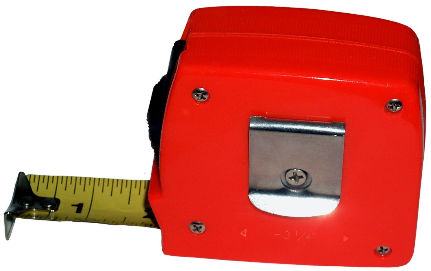 |
The common household tape measure. 16 and 25 foot are common lengths. It's hard to see in the photo, but the width of the tape is embossed just below the bottom of the belt clip, on this one it's 3 1/4". The thumb switch locks the tape. The end hook can move relative to the tape by the thickness of the metal it's made of. This way the tape measures correctly when it's either butted or hooked. |
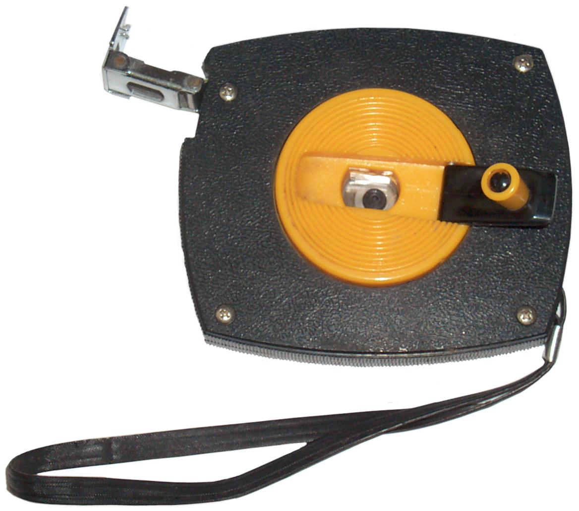 |
This 50 foot tape is similar to the 25' tape except for a tape this long a hand crank is needed to get it back inside instead of the spring used for shorter tapes. |
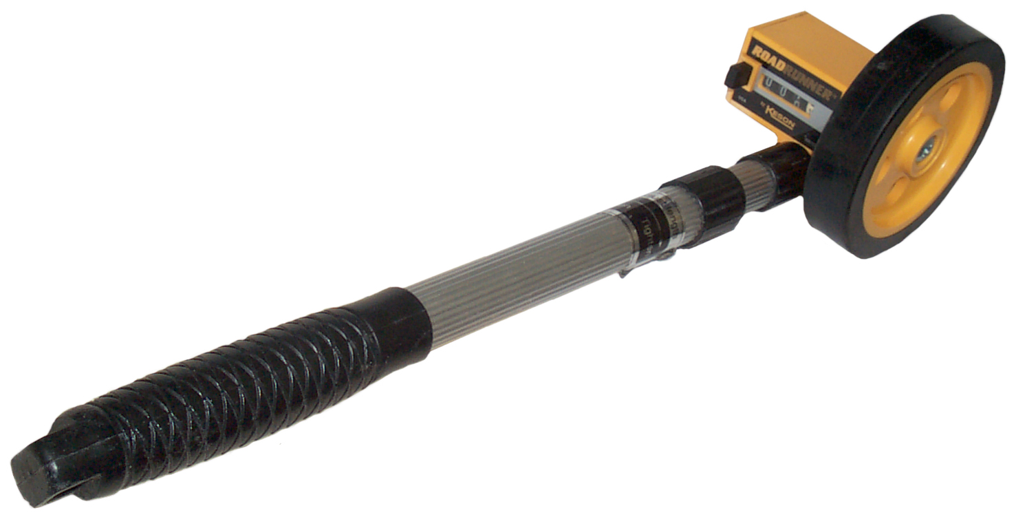 |
This measuring wheel has
a circumference of 1 foot. The left three Veeder type count
wheels read feet 000 to 999. The right wheel is
calibrated 0 to 11 inches. The handle collapses to 14" and extends to 32". Good for hard surfaces. The bicycle wheel type is better for dirt. There really is no upper limit on the distance since the wheels just roll over 999 to 000 feet. |
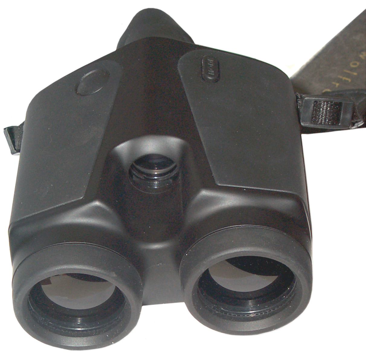 |
Bushnell Yardage Pro 400
Distance Measuring optics. Your eye looks through
the single rear eyepiece and out through the small
center lens. Superimposed on the view the mode of
operation and a circle target along with the 3 digit
range in yards to the target are displayed. The two large lens in front are probably silicon (black color), one for the IR transmitter and the other for the receiver. 5623335 Laser range finder with target quality display, 356/5.01 ; 356/139.08; 356/141.1 |
| Also see Range Finders |
Electronic Dial Gauge
2607890 Variably sensitive frequency discriminator, Petroff Merlin, Stewart Warner, 1952-08-19, - "...displacements over a wide range, such, for example, as from a few thousandths of an inch to two inches..."
Poor Man's Optical Comparator (Wiki)
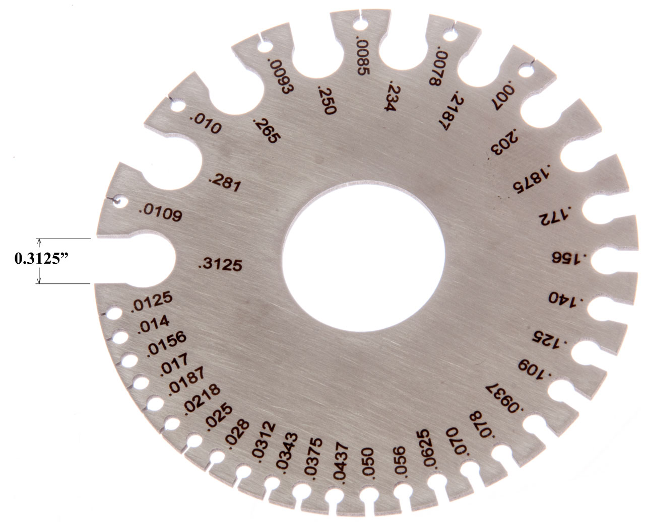
Wire - Sheet metal Gage
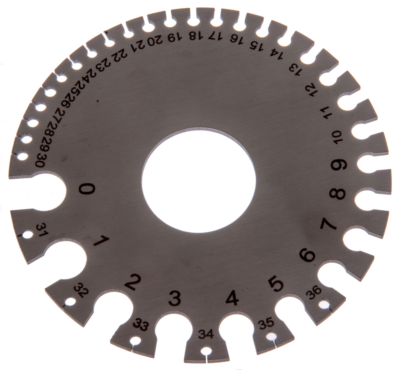
Wire - Sheet metal Gage
Used to measure the diameter of wire or the thickness of sheet metal.
Fig 1 Thickness in Gage
Fig 2 Note the distance between the flats corresponds to the label.
Cadallac Height Gage
YouTube: Accurate to 0.0001" for less than $50, 7:33 -
2135316 Point or plane finder, Lawrence V Whistler, Sanford A Whistler, 1938-11-01, - probably sold to Cadillac Gage
2440710 Micrometer height gage fixture, Russell E Bauer, Cadillac Gage Co, App: 1944-10-30, W.W.II, Pub: 1948-05-04 -
2544004 Height gauge fixture, Clarence H Bauer, Cadillac Gage Co, 1951-03-06, - looks like the one in the YouTube.
Threads
Pitch
 |
An easy way to measure the TPI is with a thread gauge. By holding the gauge to the thread with a light background you can be certain of the pitch. Sometimes at first glance a thread appears to match, but when you rock the gauge the section that matches moves back and forth that indicates the thread is slightly different for the gauge pitch. Instead of the gauge you can also use a screw. So it's very handy to have a small collection of screws and nuts in the more common sizes handy for use a measurement tools. |
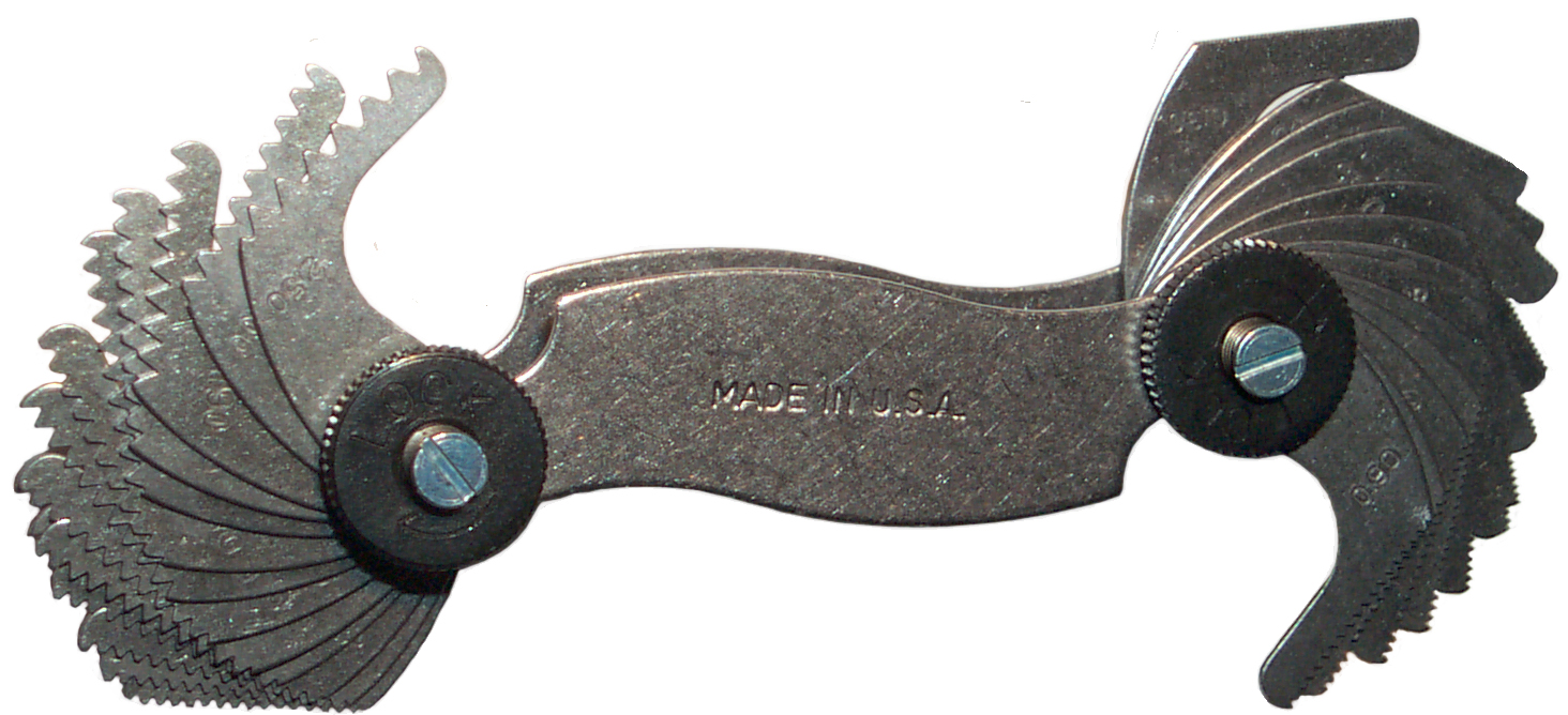 |
This is a metic thread
pitch gauge with 28 leafs. |
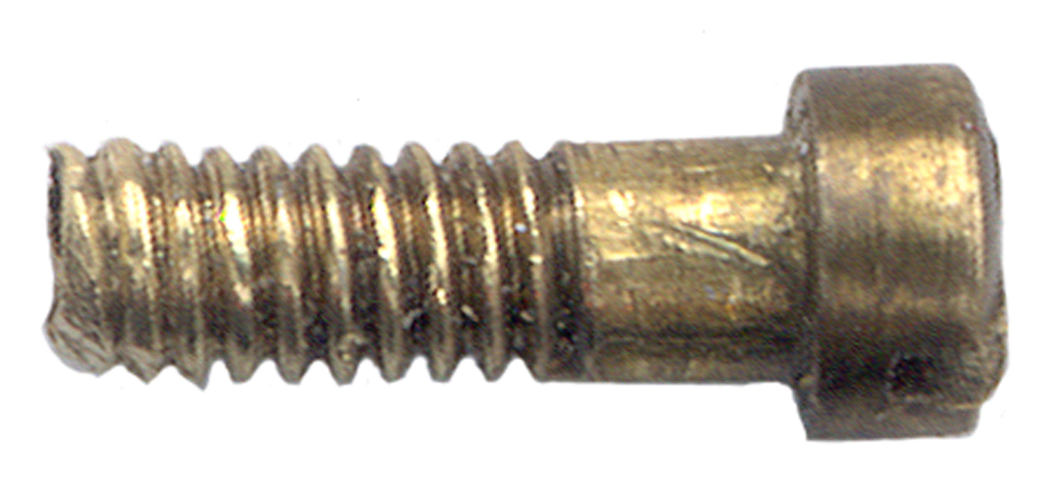 |
Another way to measure the pitch is to use a flat bed scanner. When the imaging format is Bit Map (.bmp) the image contains scale information. That's not the case for Tagged Image Format (.tif) or Joint Picture Group (.jpg) files like used in a camera where scale has no meaning. The pitch of the 4-40 brass screw shown in the photo can easily be measured by using the ruler tool in a photo processing software package like Photoshop. The screw is from a Veeder Counter. |
A nut is not a good way to determine pitch because when the fit is sloppy you really don't know what's going on.
The best way to measure an outside thread is by using a pair of ring gauges. One has it's internal thread set for the upper spec limit for the class of thread, the "GO" gauge, and the other is set at the minimum spec limit, the "NO GO" gauge.
 In
a
similar
way an internal thread can be tested with a GO - NO GO plug
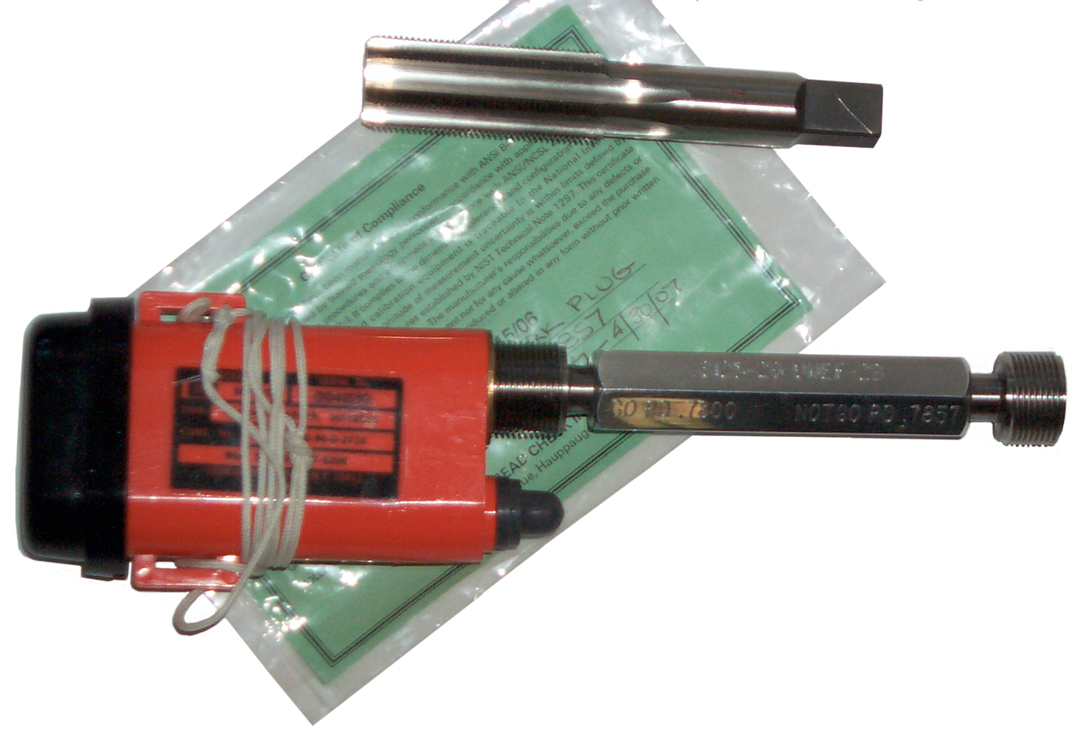
gauge. The photo shows aGO NOGO plug gauge testing the
threads in a SDU-5/E Distress Marker
Light. These were made in high volume and as the
production taps wore out the threads got to be undersize.
Running the tap shown above cleans out the threads and brings
them into spec allowing my 5BA
battery adapter to fit properly. The green paper is
the calibration certificate for the gauge.
In
a
similar
way an internal thread can be tested with a GO - NO GO plug
gauge. The photo shows aGO NOGO plug gauge testing the
threads in a SDU-5/E Distress Marker
Light. These were made in high volume and as the
production taps wore out the threads got to be undersize.
Running the tap shown above cleans out the threads and brings
them into spec allowing my 5BA
battery adapter to fit properly. The green paper is
the calibration certificate for the gauge.A good way to check the pitch diameter is using plug or ring GO NoGo gauges.
Pitch Diameter
For most cases measuring what's called the major diameter of a screw or the minor diameter of an internal thread (pin gauges are good for this) would seem to allow you to look up the thread using a thread table (Google is helpful here). But that's not the key dimension, the pitch diameter is what's important. If the points are cut off a screw thread a little more than normal the pitch diameter is not effected and the thread may be fine.Method of Wires
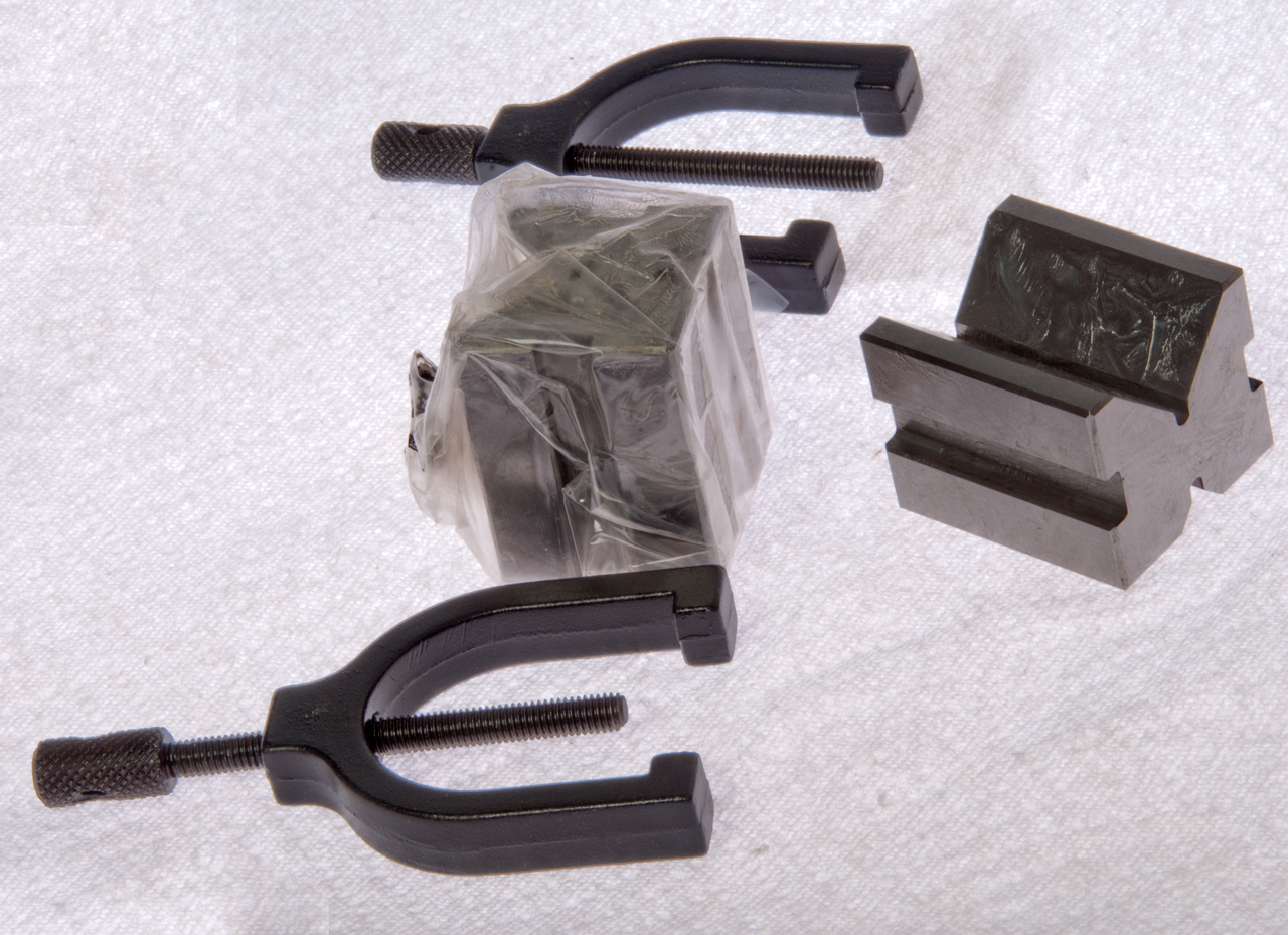
For measuring the pitch diameter of plug gauges or external threads like a screw the method of wires can be used. Three wires, all the same size, chosen so that the pins rest very near the pitch diameter on the flanks of the "V". Two pins on one side and one pin on the other side. Then a mike held in a stand can be used to measure the distance across the pins. From this can be calculated the pitch diameter of the thread. This is the metrology standard method of measuring pitch diameter.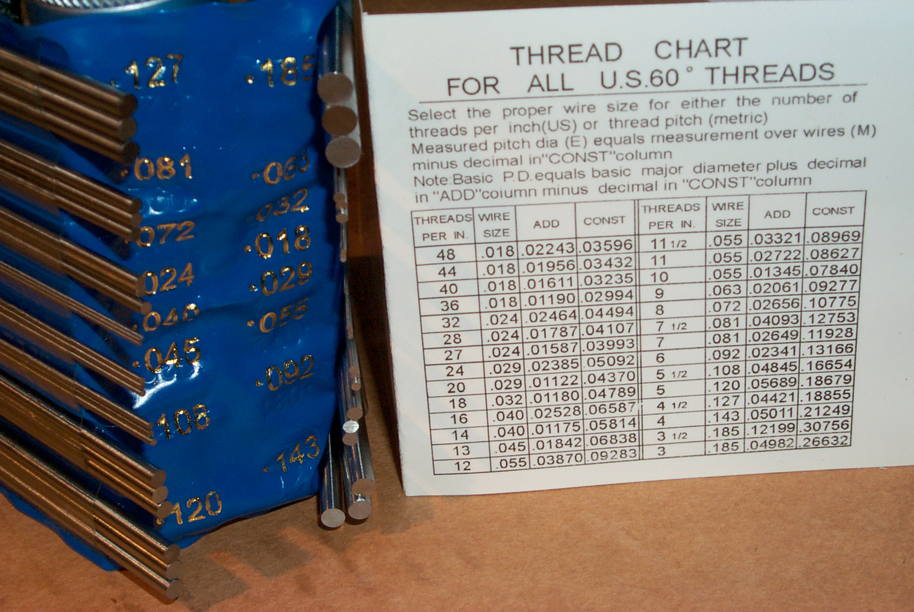 The best way
to measure the pitch diameter is by using the method of
wires. Placing two wires on one side and a single wire on
the opposite side of a thread allows miking the diameter over
the wires. By choosing the diameter of the wires they end
up sitting on the flanks of the thread hopefully near the pitch
diameter. If the crest and root have had the points cut
off the wires will still measure the pitch diameter. This
is THE way to measure thread pitch and is the way plug gauges
are measured.
The best way
to measure the pitch diameter is by using the method of
wires. Placing two wires on one side and a single wire on
the opposite side of a thread allows miking the diameter over
the wires. By choosing the diameter of the wires they end
up sitting on the flanks of the thread hopefully near the pitch
diameter. If the crest and root have had the points cut
off the wires will still measure the pitch diameter. This
is THE way to measure thread pitch and is the way plug gauges
are measured.Enco 600-0050 3 to 48 TPI (0.5 to 6 mm) Pitch Thread Wire Measuring Set. These also show up on eBay.

Using two wires on the left and one on the right to measure the metric pitch dia on a UltraFire C3 flashlight.
It takes one hand to hold the left two wires, another hand to hold the flashlight body, another hand to hold the right wire, and yet another hand to tighten the mike.
This is a 0.75 mm pitch so the 0,018" wires are used.
The two measurements (the ends are different).
Pitch = Measured over wires - CONST.
| Large
head |
Small
switch |
|
| measured |
19.201 |
18.272 |
| CONST |
0.7221 |
0.7221 |
| Pitch |
18.478 |
17.5499 |
| Pitch rounded |
18.5
mm |
17.5
mm |
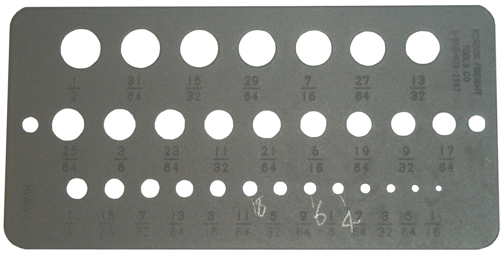
Using a hole template is not such a good way to make a measurement, but is good for a quick sanity check. I have marked the holes in this one for #4, #6 and #8 screws.
This is not too useful.
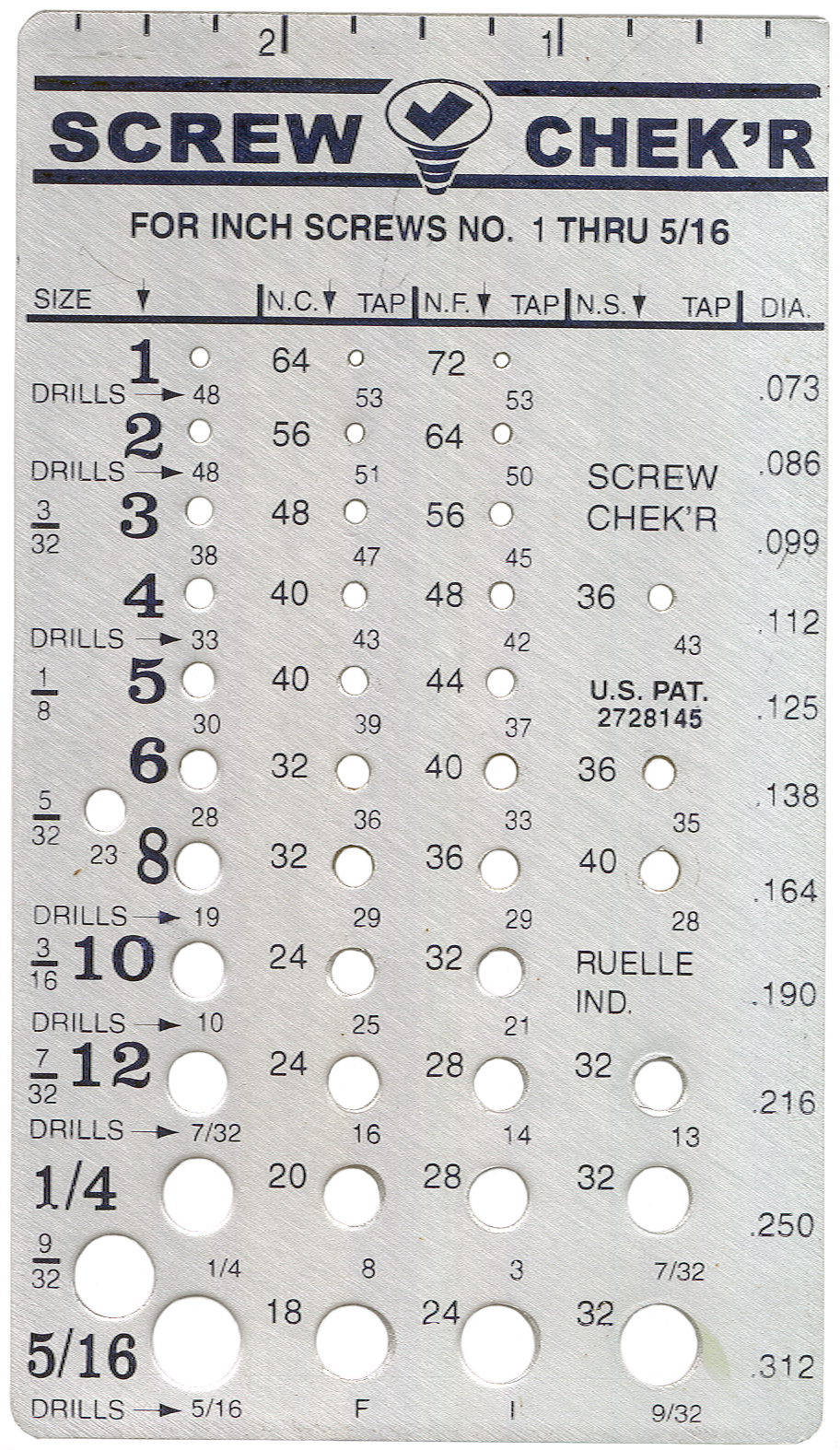
Screw Chek'R
 This is a way
to check the number size and the thread pitch. The
numbered holes to the left have no threads and are for checking
the O.D. and to the right are tapped holes to check the
pitch. A handy tool.
This is a way
to check the number size and the thread pitch. The
numbered holes to the left have no threads and are for checking
the O.D. and to the right are tapped holes to check the
pitch. A handy tool.The Inch version is shown, but there is also a Metric version. The Inch version has 28 and the Metric version 21 tapped holes.
Using both the Inch and Metric size Screw Chek'R plates for the screws from a Bunnell Telegraph sounder there are some screws that can't be categorized, either because the threads are rusty or were made before there were good thread specifications. This is where the leaf type pitch gauge comes in. The leaf type gauge clearly tells you the pitch.
For these unknown screws a test of the mating part using a modern screw is needed prior to chasing. Now knowing the number size and pitch, the thread can be chased with a die.
2728145 Screw Gauge, F.E. Holladay, Dec 27, 1955, 33/199R ; 33/555.2 - applies to both the Inch and Metric versions.
Tap Handle & Die Holder
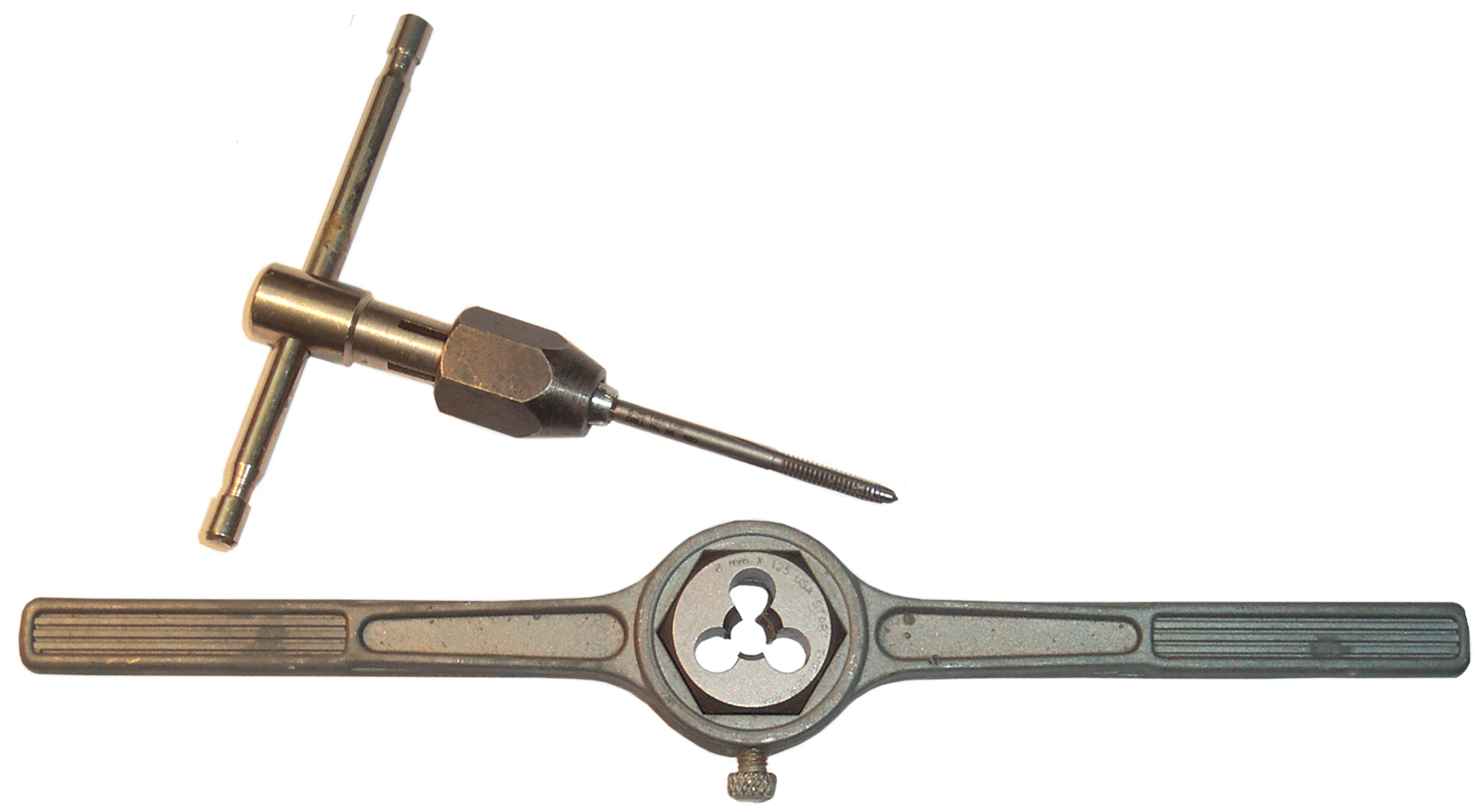 The
small taps have a square end that are 0.150" and the small tap
holder works with them. Small dies are 1" across the flats
hexagons and the small die holder is made to hold them.
The
small taps have a square end that are 0.150" and the small tap
holder works with them. Small dies are 1" across the flats
hexagons and the small die holder is made to hold them.They both, along with a number of taps and dies, fit into a 7"x7" Zip-Loc bag. I buy them on an as needed basis. If a tap drill is needed it gets put in the bag too, not with the regular drills. The store hanging card packaging is also in the bag as a handy reference to coordinate drill size to tap.